EP1327868B1 - Balance avec afficheur à mémoire - Google Patents
Balance avec afficheur à mémoire Download PDFInfo
- Publication number
- EP1327868B1 EP1327868B1 EP03000547A EP03000547A EP1327868B1 EP 1327868 B1 EP1327868 B1 EP 1327868B1 EP 03000547 A EP03000547 A EP 03000547A EP 03000547 A EP03000547 A EP 03000547A EP 1327868 B1 EP1327868 B1 EP 1327868B1
- Authority
- EP
- European Patent Office
- Prior art keywords
- measured value
- display section
- indicated
- memory display
- section
- Prior art date
- Legal status (The legal status is an assumption and is not a legal conclusion. Google has not performed a legal analysis and makes no representation as to the accuracy of the status listed.)
- Expired - Lifetime
Links
- 230000006870 function Effects 0.000 title claims description 23
- 238000005259 measurement Methods 0.000 claims description 79
- 230000004044 response Effects 0.000 claims description 3
- 238000000034 method Methods 0.000 description 9
- 210000004556 brain Anatomy 0.000 description 4
- 238000010586 diagram Methods 0.000 description 4
- 230000005540 biological transmission Effects 0.000 description 1
- 230000001419 dependent effect Effects 0.000 description 1
- 238000013208 measuring procedure Methods 0.000 description 1
- 230000001737 promoting effect Effects 0.000 description 1
- 230000000007 visual effect Effects 0.000 description 1
Images


Classifications
-
- G—PHYSICS
- G01—MEASURING; TESTING
- G01G—WEIGHING
- G01G23/00—Auxiliary devices for weighing apparatus
- G01G23/18—Indicating devices, e.g. for remote indication; Recording devices; Scales, e.g. graduated
- G01G23/36—Indicating the weight by electrical means, e.g. using photoelectric cells
- G01G23/37—Indicating the weight by electrical means, e.g. using photoelectric cells involving digital counting
- G01G23/3707—Indicating the weight by electrical means, e.g. using photoelectric cells involving digital counting using a microprocessor
-
- G—PHYSICS
- G01—MEASURING; TESTING
- G01G—WEIGHING
- G01G19/00—Weighing apparatus or methods adapted for special purposes not provided for in the preceding groups
- G01G19/44—Weighing apparatus or methods adapted for special purposes not provided for in the preceding groups for weighing persons
Definitions
- the present invention relates to a scale equipped with a memory display function, which allows, in a series of consecutive measurements, a measured value to be memory-displayed in a memory display section separately from a regular display section.
- a display section of a scale for indicating a measured value in a prior art technology, only indicates a measured value of an object being currently measured.
- a person in a continuous measurement, for example, in an incremental measurement, has to remember in his/her brain or take notes for recording each one of the measured values at each time of measurement so as to carry out such a series of measurements.
- the present invention has been made to solve the problems pertaining to the prior art technology and an object thereof is to provide a scale equipped with a memory display function that can reduce effort of a person in carrying out a series of measurements such as an incremental measurement.
- US 4773492 discloses an electronic personal weight scale for conveying weight information including a health promoting message based on departure of measured weight from ideal weight. During the measurement a current weight and weight data of previous measurements is displayed.
- FR 2564196 discloses a personal weight scale in which a current measured weight value is displayed. Moreover, the difference of the current measured weight to a previously stored weight is also displayed.
- a scale equipped with a memory display function is characterized in comprising: a regular display section for indicating a current measured value; and a memory display section for indicating said current measured value indicated in said regular display section as a previously measured value in a series of consecutive measurements.
- the scale since the scale is equipped with the regular display section and the memory display section, the person in the course of consecutive measurement no more needs to take the trouble, such as remembering in the brain or taking notes of measured values, but he/she can carry out a current measurement work by way of visual recognition without any additional effort.
- Said scale according to the present invention is further characterized in comprising a plurality of said memory display sections.
- Said scale according to the present invention is further characterized in further comprising a transfer unit for transferring a measured value indicated in said regular display section so that it can be indicated in said memory display section as a previously measured value in a series of consecutive measurements.
- the scale since the scale comprises the transfer unit, it is ensured that the measured value indicated in the memory display section represents the previously measured value in the series of consecutive measurements, such as an incremental measurement, thereby providing an easy recognition.
- Said scale according to the present invention is further characterized in further comprising: a summing unit for determining a total measured value from a current measured value indicated in said regular display section and a previously measured value in a series of consecutive measurements as indicated in said memory display section, wherein said total measured value determined in said summing unit is indicated in either one of said regular display section or said memory display section.
- a summing unit for determining a total measured value from a current measured value indicated in said regular display section and a previously measured value in a series of consecutive measurements as indicated in said memory display section, wherein said total measured value determined in said summing unit is indicated in either one of said regular display section or said memory display section.
- Said scale according to the present invention is further characterized in that said regular display section, after the measured value having been transferred by said transfer unit, indicates a tared value.
- the regular display section since the regular display section, after the measured value having been transferred therefrom by the transfer unit, indicates the tared value defined by subtracting a tare weight value from the measured value, an additional object to be measured can be loaded on a loading table and a measured value for this additional object to be measured can be obtained in a continuous manner yet with no effort without making such a troublesome work of removing the previously measured object from a loading table of the scale.
- Said scale according to the present invention is further characterized in that, if said regular display section indicates either "0" or "a negative value", said transfer unit executes no transfer operation to indicate said measured value in said memory display section as a previously measured value in a series of consecutive measurements.
- said transfer unit since in case of "0" or "a negative value” indicated in the regular display section, the value would not be transferred by the transfer unit to the memory display section, therefore it is ensured that only the measured value acquired in a measurement for an object actually loaded on the loading table can be transferred into the memory display section.
- Said scale according to the present invention is further characterized in that said transfer unit comprises: a manual transfer switch for a manual input upon executing a transfer operation; and a manual transfer control section which, in response to an input to said manual transfer switch, controls the transfer operation to be executed so that a measured value indicated in said regular display section may be indicated in said memory display section as a previously measured value in a series of consecutive measurements.
- the transfer unit since the transfer unit comprises the manual transfer switch and the manual transfer control section, therefore based on the determination by the person in charge of the measurement, only the necessary measured value at each measurement can be transferred to the memory display section.
- Said scale according to the present invention is further characterized in that said transfer unit comprises : a clock section for clocking the time; and an automatic transfer control section which, after an elapse of a predetermined time, as clocked in said clock section, while the measured value indicated in said regular display section being held unchanged, controls the transfer operation to be executed so that a measured value indicated in said regular display section may be transferred to and indicated in said memory display section as a previously measured value in a series of consecutive measurements.
- the transfer unit comprises the clock section and the automatic transfer control section, therefore the measured value can be transferred to the memory display section without causing the person in measurement to take the trouble of executing the operation.
- Said scale according to the present invention is further characterized in further comprising a tare subtraction unit for subtracting a weight equivalent to a tare from a measured value indicated in said regular display section.
- a tare subtraction unit for subtracting a weight equivalent to a tare from a measured value indicated in said regular display section.
- Fig. 1 is a perspective view showing an overview of a scale equipped with a memory display section according to the present invention
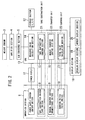
- Fig. 2 is a block diagram illustrating a configuration thereof
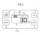
- Fig. 3 is a detailed view showing details of a display section and an operation section thereof.
- a scale equipped with a memory display function comprises a case 1 forming an exterior package and a loading table 2 on which an object to be measured is to be placed, both together constructing a principle profile of the scale.
- the case 1 includes an operation section 6, a display section 18, and power supplies 11 disposed in a front part of the case 1, and further, a weight sensor 3, am amplifier section 4, an A/D converter section 5, a storage section 12 and a CPU 13, each disposed in an inside of the case 1, which together construct an overall unit of the scale.
- the weight sensor 3 receives a transmission of a load from the loading table 2 and converts it into an electric signal.
- the amplifier section 4 amplifies the analog signal from the weight sensor 3.
- the A/D converter section 5 converts the analog signal from the amplifier section 4 into a digital signal.
- the power supplies 11, 11 are supply sources of electric power to respective components of an electric system, and in this embodiment, solar batteries may be used. It is to be noted that the power supply 11 may be implemented in the form of other power supply, for example, a dry battery, an AC adapter and so on.
- the display section 18 indicates respective results such as measured values.
- the display section 18 comprises a regular display section 19 for indicating a current measured value or a total measured value and a plurality (three) of memory display sections (L,C,R) 20 for indicating previously measured values in a series of consecutive measurements.
- the regular display section 19 may also indicate the measured value subtracted by a weight equivalent to a tare after the measured value having been transferred by a transfer unit 22, which will be described later.
- the operation section 6 serves as a section for executing operations for a variety of functions.
- the operation section 6 comprises : a power supply switch (ON/OFF switch) 7 for supplying the electric power from the power supplies 11, 11 to respective components of the electric system; a tare subtraction switch (TARE switch) 8 for subtracting the weight equivalent to the tare from the measured value to be indicated in the regular display section 19; a manual transfer switch (MEMORY/TARE switch) 9 for transferring the measured value indicated in the regular display section 19 such that said measured value may be indicated in the memory display section 20 as the previously measured value in a series of consecutive measurement; and a summing switch (TOTAL switch) 10 for summing up the current measured value indicated in the regular display section 19 and the previously measured values in the series of consecutive measurements as indicated in the memory display sections 20.
- a power supply switch ON/OFF switch
- TARE switch tare subtraction switch
- MEMORY/TARE switch manual transfer switch
- TOTAL switch summing switch
- the storage sections (such as L, C and R) 12 store various data, such as previously measured values in the series of consecutive measurements as indicated in the memory display sections (L, C and R) 20.
- the CPU 13 executes controls and arithmetic operations for respective components.
- the CPU may comprise: a measured value calculation section 14 for calculating the measured value based on the digital signal from the A/D converter section 5; a tare subtraction control section 15 for controlling a subtracting operation of the weight equivalent to the tare from the current measured value or the total measured value indicated in the regular display section 19; a manual transfer control section 16, which in conjunction with an input to the manual transfer switch 9, controls the transfer operation to be executed so that the current measured value or the total measured value indicated in the regular display section 19 may be transferred and indicated in the memory display section 20 as the previously measured value in the series of consecutive measurements; a total value calculation section 17, which in conjunction with an input to the summing switch 10, calculates the total measured value from the current measured value indicated in the regular display section 19 and the previously measured values in the series of consecutive measurements as indicated in the memory display sections 20; and so on.
- the tare subtraction switch 8 and the tare subtraction control section 15 together construct a tare subtraction unit 21 for subtracting the weight equivalent to the tare from the current measured value or the total measured value indicated in the regular display section 19.
- the manual transfer switch 9 and the manual transfer control section 16 together construct a transfer unit 22 for transferring the measured value indicated in the regular display section 19 so that said measured value may be indicated in the memory display section 20 as the previously measured value in the series of consecutive measurements. It is to be noted that the transfer unit 22 would not execute any transfer operation when the regular display section 19 indicates either one of "0" or " a negative value".
- the summing switch 10 and the total value calculation section 17 together construct a summing unit 23 for determining the total measured value from the previously measured values in the series of consecutive measurements as indicated in the memory display sections 20 and the current measured value indicated in the regular display section 19.
- Fig. 4 is a flow chart illustrating the operation and a process flow of the scale equipped with the memory display function according to the present invention
- Figs. 5A through 5J show some examples of indication appearing thereupon in the display section.
- Step 1 of Fig. 4 when the power supply switch 7 is turned on (Step 1 of Fig. 4), the power supplies 11, 11 supply the electric power to respective components of the electric system so as to initiate those components of the electric system (Step 2 of Fig. 4), and the regular display section 19 indicates "0" (Step 3 of Fig. 4 and Fig. 5A) showing the scale being ready for a measurement.
- the weight sensor 3 converts the load from the object to be measured into the analog signal, which is in turn amplified in the amplifier section 4, and this amplified analog signal is further converted into the digital signal in the A/D converter section 5, and then, based on this digital signal, the measured value calculation section 14 calculates the measured value to carry out the measurement of the object to be measured (NO in Step 4 of Fig. 4), so that a current measured value may be indicated in the regular display section 19 (Step 5 of Fig. 4 and Fig. 5B).
- Step 7 of Fig. 4 and Fig. 5A the process returns to Step 4 to repeat the similar operations as above.
- Step 8 determines it as NO, and no increment takes place in the memory counter within the CPU even if the manual transfer switch 9 is turned on.
- the current measured value indicated in the regular display section 19 is stored in the storage section (L) 12. Also, through the transfer control in the manual transfer control section 16, the current measured value indicated in the regular display section 19 is indicated in the memory display section (L) 20 as a previously measured value in a series of consecutive measurements. Then, the regular display section 19 after the transfer operation indicates "0" representing the tare subtracted value (Step 11 of Fig. 4 and Fig. 5E).
- this memory counter represents other than "1" (NO in Step 10 of Fig. 4), that is, when the measured value is indicated in the memory display section (L) 20 in the last time measurement as the previously measured value in a series of consecutive measurement (Fig. 5C), then it is further determined whether or not this memory counter represents "2" (Step 12 of Fig. 4).
- the current measured value indicated in the regular display section 19 is stored in the storage section (C) 12. Also, through the transfer control in the manual transfer control section 16, the current measured value indicated in the regular display section 19 is indicated in the memory display section (c) 20 as the previously measured value in a series of consecutive measurements. Then, the regular display section 19 after the transfer operation indicates "0" representative of the tare subtracted value (Step 13 of Fig. 4 and Fig. 5F).
- the memory counter represents other than "2" (NO in Step 12 of Fig. 4), that is, when the measured value is indicated in the memory display section (C) 20 in the last time measurement as the previously measured value in a series of consecutive measurement (Fig. 5D), then the current measured value indicated in the regular display section 19 is stored in the storage section (R) 12. Also, through the transfer control in the manual transfer control section 16, the current measured value indicated in the regular display section 19 is indicated in the memory display section (R) 20 as a previously measured value in a series of consecutive measurements. Then, the regular display section 19 after the transfer operation indicates "0" representing the tare subtracted value (Step 14 of Fig. 4 and Fig. 5G).
- Step 15 of Fig. 4 If the manual transfer switch 9 is not turned on (NO in Step 8 of Fig. 4) as well as after Step 11, 13 and 14, it is determined whether or not the summing switch 10 is turned on (Step 15 of Fig. 4).
- the process returns to Step 4 and repeats the operations in a similar manner.
- the total value calculation section 17 calculates the total measured value from the current measured value indicated in the regular display section 19 and the previously measured values in a series of consecutive measurements as indicated in the memory display sections 20 (in this example, operation with respect to the example of display of Fig. 5H), and the regular display section 19 indicates the determined total measured value with indicative characters "TOTAL" (Step 16 of Fig. 4 and Fig. 5I). It is to be noted that at this time, those values stored in the storage section (L, C and R) 12 , the previously measured values indicated in the memory display sections (L,C and R) 20 and the memory counter are all cleared.
- Step 17 of Fig. 4 the process returns to Step 7 and repeats the operations in a similar manner.
- the tare subtraction switch 8 is not turned on (NO in Step 17 of Fig. 4) and also the manual transfer switch 9 is not turned on (NO in Step 18 of Fig. 4)
- the process returns to Step 17 and repeats the operations in a similar manner.
- the manual transfer switch 9 is turned on (YES in Step 18 of Fig. 4)
- the total measured value indicated in the regular display section 19 is stored in the storage section (L) 12.
- the memory counter is incremented by "1"
- the total measured value indicated in the regular display section 19 is indicated in the memory display section (L) 20 as the previously measured value in a series of consecutive measurements.
- the regular display section 19 after the transfer operation indicates "0" representative of the tare subtracted value (Step 19 of Fig. 4 and Fig. 5J).
- Step 4 the process repeats the operations in a similar manner. It is to be noted that in the course of executing steps as discussed above, if the value indicated in the regular display section 19 is not changed in an elapse of a predetermined time, or if the power supply switch is turned off, then the power supply is shut down.
- the scale equipped with the memory display function comprises the memory display section (L, C and R) 20 separately from the regular display section 19, therefore in such a condition of measurement having additional objects placed sequentially on the loading table (i.e., an incremental measurement), the current measuring procedure can be carried out without taking notes while at the same time confirming the previously measured values, such as the last time measured value, the one before the last time measured value and so on.
- the scale equipped with the memory display function comprises the transfer unit 22 constitutive of the manual transfer switch 9 and the manual transfer control section 16, therefore the current measuring operation can be carried out while selecting only those specific ones required as the previously measured values in a series of consecutive measurements among the current measured values and total measured values with the aid of the manual transfer control section 16 actuated by the manual transfer switch 9.
- those selected previously measured values in the series of consecutive measurements are exclusively indicated in the memory display sections (L, C and R) 20, it can be surely recognized that the indicated values are the previously measured values in a series of consecutive measurements.
- the transfer unit 22 would not execute the transfer operation to the memory display sections (L, C and R) 20, therefore it is ensured that only the measured value acquired when the object to be measured is actually placed on the loading table 2 can be transferred.
- the summing unit 23 since the summing unit 23 is provided, a person in charge of measurement no more needs to calculate by himself/herself but can recognize the total measured value of the current measured value indicated in the regular display section 19 and the previously measured values in a series of consecutive measurements as indicated in the memory display sections (L, C and R) 20.
- a series of consecutive measurements can be carried out, while eliminating those particular values indicated in the regular display section 19 that have no need to be transferred to the memory display section 20. Yet further, a series of consecutive measurements can be carried out without adding the objects to be measured onto the loading table in a sequence manner.
- three memory display sections 20 are used for indicating the previously measured values in a series of consecutive measurements but only one memory display section may be employed.
- a series of consecutive measurements may be facilitated more without the trouble of taking notes of measured values. This can be achieved by increasing the number of storage sections 12 corresponding to the number of memory display sections 20 so as to execute the similar operations.
- the total measured value summed up by the summing unit 23 is indicated in the regular display section 19, the total measured value may be indicated in the memory display section 20 or both of the regular display section 19 and the memory display section 20.
- the transfer unit 22 may be made of a clock section 24 and an automatic transfer control section 25.
- the clock section 24 clocks the time.
- the automatic transfer control section 25 after an elapse of a predetermined time, as clocked in the clock section 24, while the current measured value or the total measured value indicated in said regular display section 19 being held unchanged, controls the transfer operation to be executed, as similarly to the above case where the manual transfer switch being turned on, so that the currently measured value or the total measured value indicated in the regular display section 19 may be transferred to and indicated in the memory display section 20 as the previously measured value in a series of consecutive measurements.
- the measured value can be transferred into the memory display section without any trouble of executing operations by the person in measuring.
- a scale equipped with a memory display function comprises a regular display section and a memory display section, therefore a measurement procedure can be carried out visually without causing the trouble of remembering in the brain or taking notes of measured values, thereby increasing the efficiency.
- the measuring work can be facilitated, thereby further increasing the working efficiency.
- a person in charge of measuring work can recognize a total measured value without calculating by himself/herself, thereby providing a convenient way of measurement.
- the measured value indicated in the memory display section represents a previously measured value in a series of consecutive measurements, thereby facilitating an easy recognition of the measured value with fewer errors.
- the transfer unit is constitutive of a manual transfer switch and a manual transfer control section, the current measuring work can be carried out while selecting only specific values required as the previously measured values in a series of consecutive measurements among those measured current measured value and total measured value, thereby facilitating a convenient use of the scale.
- the transfer unit may be constitutive of a clock section and an automatic transfer control section, the person in charge of measurement work has no more need to take the trouble of executing the operation but the measured value can be transferred into the memory display section automatically, thereby reducing an effort in measuring work.
- the regular display section after the measured value having been transferred by the transfer unit, indicates a tared value, therefore an additional object to be measured can be placed on the loading table without unloading a previously measured object from the loading table, thus to obtain the measured value of this added object to be measured without any trouble yet in a continuous manner.
- the transfer unit would not execute any transfer operation of the value into the.memory display section, therefore it.is ensured that the measured value acquired only when the object to be measured is actually placed on the loading table can be transferred into the memory display section, thereby preventing a wrong operation.
- a series of consecutive measurements can be carried out while eliminating those measured values that are not required to be transferred to the memory display section, thereby providing an improved usability. Still advantageously, a series of consecutive measurements can be carried out without adding the object to be measured onto the loading table in sequence, and so a plenty of objects can be handled.
Landscapes
- Physics & Mathematics (AREA)
- General Physics & Mathematics (AREA)
- Engineering & Computer Science (AREA)
- Computer Hardware Design (AREA)
- Microelectronics & Electronic Packaging (AREA)
- Arrangements For Transmission Of Measured Signals (AREA)
- Measurement Of Unknown Time Intervals (AREA)
- Indication And Recording Devices For Special Purposes And Tariff Metering Devices (AREA)
- Cash Registers Or Receiving Machines (AREA)
- Measuring Instrument Details And Bridges, And Automatic Balancing Devices (AREA)
Claims (5)
- Balance pourvue d'une fonction d'affichage à mémoire, comprenant :une section d'affichage (18) ayant une section d'affichage régulière (19) pour indiquer une valeur mesurée actuelle et indiquer "0" représentant une valeur de tare soustraite, au lieu de la valeur mesurée actuelle, après que la valeur mesurée actuelle a été transférée comme la valeur mesurée précédemment dans une mesure par accroissements et une pluralité de sections d'affichage à mémoire (20) servant à indiquer chacune la valeur mesurée actuelle indiquée dans ladite section d'affichage régulière (19) comme une valeur mesurée précédemment ; etune unité de transfert (22) pour transférer la valeur mesurée actuelle indiquée dans ladite section d'affichage régulière (19) de façon que la valeur mesurée actuelle puisse être indiquée comme la valeur mesurée précédemment dans la mesure par accroissements dans l'une desdites sections d'affichage à mémoire (20) dans laquelle aucune valeur mesurée précédemment dans la mesure par accroissements n'est indiquée.
- Balance équipée d'une fonction d'affichage à mémoire selon la revendication 1, comprenant de plus : une unité de sommation (23) pour déterminer une valeur mesurée totale à partir d'une valeur actuelle indiquée dans ladite section d'affichage régulière (19) et d'une valeur mesurée précédemment dans la mesure par accroissements telle qu'indiquée dans ladite section d'affichage à mémoire (20), dans laquelle ladite section d'affichage régulière (19) indique la valeur mesurée totale déterminée par ladite unité de sommation (23) au lieu de la valeur mesurée actuelle et indique "0" représentant une valeur de tare soustraite, au lieu de la valeur mesurée totale, après que la valeur mesurée totale a été transférée comme la valeur mesurée précédemment dans la mesure par accroissements par ladite unité de transfert (22) et ladite unité de transfert (22) transfère la valeur mesurée totale indiquée dans ladite section d'affichage régulière (19) de façon que la valeur mesurée totale puisse être indiquée dans l'une desdites sections d'affichage à mémoire (20) comme la valeur mesurée précédemment dans la mesure par accroissements.
- Balance équipée d'une fonction d'affichage à mémoire selon la revendication 1 ou 2, dans laquelle ladite unité de transfert (22) comprend un commutateur manuel de transfert (9) pour une entrée manuelle lors de l'exécution d'une opération de transfert et une unité de commande manuelle de transfert (16) qui, en réponse à une entrée audit commutateur manuel de transfert (9), commande d'effectuer l'opération de transfert de façon qu'une valeur mesurée actuelle indiquée dans ladite section d'affichage régulière (19) puisse être indiquée dans ladite section d'affichage à mémoire (20) comme une valeur mesurée précédemment dans la mesure par accroissements, comprenant de plus une unité de soustraction de tare (21) pour soustraire un poids équivalent à une tare d'une valeur mesurée actuelle indiquée dans ladite section d'affichage régulière (19), après que la valeur mesurée actuelle a été indiquée par ladite unité d'affichage régulière et avant que ledit commutateur manuel de transfert (9) soit actionné.
- Balance équipée d'une fonction d'affichage à mémoire selon la revendication 3, dans laquelle ladite unité de transfert (22) comprend un commutateur manuel de transfert (9) pour une entrée manuelle lors de l'exécution d'une opération de transfert et une section de commande manuelle de transfert (16) qui, en réponse à une entrée audit commutateur manuel de transfert (9), commande d'effectuer l'opération de transfert de façon qu'une valeur mesurée totale indiquée dans ladite section d'affichage régulière (19) puisse être indiquée dans ladite section d'affichage à mémoire (20) comme une valeur mesurée précédemment dans la mesure par accroissements, comprenant de plus une unité de soustraction de tare (21) pour soustraire un poids équivalent à une tare d'une valeur mesurée totale indiquée dans ladite section d'affichage régulière (19), après que la valeur mesurée totale a été indiquée par ladite unité d'affichage régulière et avant que ledit commutateur manuel de transfert (9) soit actionné.
- Balance équipée d'une fonction d'affichage à mémoire selon l'une quelconque des revendications 1 à 4, dans laquelle, si ladite section d'affichage régulière (19) indique soit "0" soit "valeur négative", ladite unité de transfert (22) n'effectue aucune opération de transfert pour indiquer ladite valeur mesurée dans ladite section d'affichage à mémoire (20) comme une valeur mesurée précédemment dans la mesure par accroissements.
Applications Claiming Priority (2)
| Application Number | Priority Date | Filing Date | Title |
|---|---|---|---|
| JP2002003001 | 2002-01-10 | ||
| JP2002003001A JP3830034B2 (ja) | 2002-01-10 | 2002-01-10 | メモリー表示機能付き秤 |
Publications (2)
| Publication Number | Publication Date |
|---|---|
| EP1327868A1 EP1327868A1 (fr) | 2003-07-16 |
| EP1327868B1 true EP1327868B1 (fr) | 2006-05-17 |
Family
ID=19190814
Family Applications (1)
| Application Number | Title | Priority Date | Filing Date |
|---|---|---|---|
| EP03000547A Expired - Lifetime EP1327868B1 (fr) | 2002-01-10 | 2003-01-10 | Balance avec afficheur à mémoire |
Country Status (5)
| Country | Link |
|---|---|
| US (1) | US6989494B2 (fr) |
| EP (1) | EP1327868B1 (fr) |
| JP (1) | JP3830034B2 (fr) |
| CN (1) | CN1249411C (fr) |
| DE (1) | DE60305216T2 (fr) |
Families Citing this family (14)
| Publication number | Priority date | Publication date | Assignee | Title |
|---|---|---|---|---|
| US7138585B2 (en) * | 2003-05-07 | 2006-11-21 | Sunbeam Products, Inc | Scale with message display |
| US7193163B1 (en) * | 2004-03-31 | 2007-03-20 | Kesselman Joshua D | Handheld electronic scale with background digital animation on display screen |
| FR2880112B1 (fr) * | 2004-12-23 | 2007-02-09 | Seb Sa | Pese-personne |
| US20070102666A1 (en) * | 2005-10-24 | 2007-05-10 | Cohen Martin A | Illuminated weight scale control |
| JP4758209B2 (ja) * | 2005-11-30 | 2011-08-24 | 大和製衡株式会社 | 計量装置 |
| JP4999555B2 (ja) * | 2006-09-25 | 2012-08-15 | 株式会社タニタ | 個人別出力形式カスタマイズ機能付き身体測定装置 |
| CN103090947A (zh) * | 2013-01-19 | 2013-05-08 | 林瑞别 | 一种短信提示功能的电子体重秤 |
| EP3447458B1 (fr) * | 2016-06-10 | 2021-11-24 | Shinko Denshi Co., Ltd. | Balance électronique avec unité d'affichage et un procédé d'affichage |
| US10254153B2 (en) * | 2016-08-12 | 2019-04-09 | Medline Industries, Inc. | Weight scale and corresponding systems and methods for preventing advancement of congestive heart failure |
| CN106498489B (zh) * | 2016-12-16 | 2019-06-25 | 南京晶升能源设备有限公司 | 蓝宝石单晶炉称重检测系统、传感器滤波方法及切换方法 |
| USD830211S1 (en) * | 2017-03-10 | 2018-10-09 | Weighmax Group | Balance |
| CN110260967A (zh) * | 2019-07-23 | 2019-09-20 | 厦门大学 | 一种提供开源数据接口的大批量称量电子秤 |
| USD926061S1 (en) * | 2019-09-17 | 2021-07-27 | Yan Jiang | Electronic scale |
| USD992142S1 (en) * | 2021-11-17 | 2023-07-11 | Ika-Werke Gmbh & Co. Kg | Laboratory apparatus |
Family Cites Families (20)
| Publication number | Priority date | Publication date | Assignee | Title |
|---|---|---|---|---|
| US4301879A (en) * | 1980-02-27 | 1981-11-24 | Dubow Arnold A | Body weight scale with historical record display |
| US4423792A (en) * | 1981-06-17 | 1984-01-03 | Cowan Donald F | Electronic scale apparatus and method of controlling weight |
| JPS58215515A (ja) * | 1982-06-09 | 1983-12-15 | Hitachi Ltd | 電子体重計 |
| JPS59109828A (ja) | 1982-12-15 | 1984-06-25 | Kubota Ltd | 新生児計重用スケ−ル |
| FR2564196B1 (fr) | 1984-05-11 | 1988-12-02 | Rival Michel | Pese-personne electronique |
| US5084832A (en) * | 1986-11-14 | 1992-01-28 | Ishida Scales Mfg. Co., Ltd. | Input device for combinational weighing system |
| US4992929A (en) * | 1986-11-14 | 1991-02-12 | Ishida Scales Mfg. Co., Ltd. | Method of system operation |
| US4773492A (en) * | 1987-03-24 | 1988-09-27 | Edward Ruzumna | Apparatus for promoting good health |
| US5121328A (en) * | 1989-01-31 | 1992-06-09 | Casio Computer Co., Ltd. | Fee calculating apparatus for calculating delivery fee of parcel in accordance with its weight, length, and delivery area |
| CN2096747U (zh) | 1991-04-09 | 1992-02-19 | 杨迪梁 | 改良的机械秤 |
| JP3124369B2 (ja) | 1992-04-14 | 2001-01-15 | 大和製衡株式会社 | 複数台の組合せ秤における操作表示装置 |
| CH688980A5 (de) * | 1993-02-26 | 1998-06-30 | Mettler Toledo Gmbh | Verfahren zum Anwaehlen und Konfigurieren von Waegeprogrammen in einer Waage und eine Waage zur Ausfuehrung des Verfahrens . |
| GB2350433B (en) | 1996-05-08 | 2001-01-17 | Automotive Controls Corp | Wire harness for throttle position sensor testing |
| CN2371552Y (zh) | 1997-07-10 | 2000-03-29 | 穆润生 | 智能型装载机称重装置 |
| DE19860295C2 (de) * | 1998-12-18 | 2003-04-24 | Francotyp Postalia Ag | Verfahren und Anordnung zur Steuerung einer dynamischen Waage |
| JP4159173B2 (ja) | 1999-04-09 | 2008-10-01 | 株式会社イシダ | 対面販売システム |
| GB9912226D0 (en) | 1999-05-27 | 1999-07-28 | Holmes Pauline A | Interactive weighing machine |
| JP2001317990A (ja) | 2000-05-10 | 2001-11-16 | Toshiba Tec Corp | 電子秤 |
| DE20020198U1 (de) | 2000-11-28 | 2001-05-31 | Müller, Frank, 91341 Röttenbach | Erweiterte elektronische Anzeige und Datenspeicherfähigkeit von Personenwaagen |
| DE10063537C1 (de) * | 2000-12-20 | 2002-07-25 | Sartorius Gmbh | Anzeige- und Bedienkopf für eine elektronische Waage |
-
2002
- 2002-01-10 JP JP2002003001A patent/JP3830034B2/ja not_active Expired - Fee Related
-
2003
- 2003-01-06 US US10/336,788 patent/US6989494B2/en not_active Expired - Fee Related
- 2003-01-10 CN CNB031015352A patent/CN1249411C/zh not_active Expired - Fee Related
- 2003-01-10 EP EP03000547A patent/EP1327868B1/fr not_active Expired - Lifetime
- 2003-01-10 DE DE60305216T patent/DE60305216T2/de not_active Expired - Lifetime
Also Published As
| Publication number | Publication date |
|---|---|
| DE60305216T2 (de) | 2007-02-15 |
| CN1249411C (zh) | 2006-04-05 |
| CN1431473A (zh) | 2003-07-23 |
| JP2003207388A (ja) | 2003-07-25 |
| DE60305216D1 (de) | 2006-06-22 |
| EP1327868A1 (fr) | 2003-07-16 |
| US6989494B2 (en) | 2006-01-24 |
| US20030127254A1 (en) | 2003-07-10 |
| JP3830034B2 (ja) | 2006-10-04 |
Similar Documents
| Publication | Publication Date | Title |
|---|---|---|
| EP1327868B1 (fr) | Balance avec afficheur à mémoire | |
| US5434495A (en) | Cognition device for battery residual capacity | |
| JP5062332B2 (ja) | 重量測定装置 | |
| CN102959368B (zh) | 体重管理装置 | |
| JPH11195435A (ja) | 充電装置 | |
| US8664919B2 (en) | Remaining battery power calculation circuit | |
| JP2501596B2 (ja) | 電子秤 | |
| US5870025A (en) | Power-supply apparatus and its mounting-completion indication method | |
| US4328874A (en) | Digital weighing scale with selectable computational parameters | |
| JP2010019653A (ja) | 電池残容量算出システム | |
| JPH0819184A (ja) | 電源装置およびその取付完了表示方法 | |
| CN108791722B (zh) | 一种船舶液舱装载量的测量方法及装置 | |
| JP3226429B2 (ja) | 電池の充電方法及び電源装置を有する装置 | |
| EP0692160B1 (fr) | Convertisseur analogique/numerique a integration a correction de temperature | |
| TWI832892B (zh) | 計測系統 | |
| KR100552449B1 (ko) | 컴퓨터 연결형 디지털 체중계 | |
| EP0439255A1 (fr) | Appareil électronique avec mesurage de profondeur | |
| JP3119952B2 (ja) | 充電制御装置および充電制御方法 | |
| JP2008170169A (ja) | 電子機器 | |
| JP3415352B2 (ja) | 計測システム | |
| KR200389845Y1 (ko) | 휴대폰 거치형 디지털 체중계 | |
| JPS58198732A (ja) | 減算演算式はかり | |
| JP2940115B2 (ja) | 水深計付電子機器 | |
| JP2595343B2 (ja) | 料金算出装置 | |
| JP2575126B2 (ja) | 電子機器 |
Legal Events
| Date | Code | Title | Description |
|---|---|---|---|
| PUAI | Public reference made under article 153(3) epc to a published international application that has entered the european phase |
Free format text: ORIGINAL CODE: 0009012 |
|
| 17P | Request for examination filed |
Effective date: 20030116 |
|
| AK | Designated contracting states |
Designated state(s): AT BE BG CH CY CZ DE DK EE ES FI FR GB GR HU IE IT LI LU MC NL PT SE SI SK TR |
|
| AX | Request for extension of the european patent |
Extension state: AL LT LV MK RO |
|
| AKX | Designation fees paid |
Designated state(s): DE FR GB |
|
| 17Q | First examination report despatched |
Effective date: 20040924 |
|
| GRAP | Despatch of communication of intention to grant a patent |
Free format text: ORIGINAL CODE: EPIDOSNIGR1 |
|
| GRAS | Grant fee paid |
Free format text: ORIGINAL CODE: EPIDOSNIGR3 |
|
| GRAA | (expected) grant |
Free format text: ORIGINAL CODE: 0009210 |
|
| AK | Designated contracting states |
Kind code of ref document: B1 Designated state(s): DE FR GB |
|
| REG | Reference to a national code |
Ref country code: GB Ref legal event code: FG4D |
|
| REF | Corresponds to: |
Ref document number: 60305216 Country of ref document: DE Date of ref document: 20060622 Kind code of ref document: P |
|
| ET | Fr: translation filed | ||
| PLBE | No opposition filed within time limit |
Free format text: ORIGINAL CODE: 0009261 |
|
| STAA | Information on the status of an ep patent application or granted ep patent |
Free format text: STATUS: NO OPPOSITION FILED WITHIN TIME LIMIT |
|
| 26N | No opposition filed |
Effective date: 20070220 |
|
| REG | Reference to a national code |
Ref country code: FR Ref legal event code: PLFP Year of fee payment: 14 |
|
| REG | Reference to a national code |
Ref country code: FR Ref legal event code: PLFP Year of fee payment: 15 |
|
| PGFP | Annual fee paid to national office [announced via postgrant information from national office to epo] |
Ref country code: FR Payment date: 20161215 Year of fee payment: 15 |
|
| PGFP | Annual fee paid to national office [announced via postgrant information from national office to epo] |
Ref country code: DE Payment date: 20170104 Year of fee payment: 15 |
|
| PGFP | Annual fee paid to national office [announced via postgrant information from national office to epo] |
Ref country code: GB Payment date: 20170104 Year of fee payment: 15 |
|
| REG | Reference to a national code |
Ref country code: DE Ref legal event code: R119 Ref document number: 60305216 Country of ref document: DE |
|
| GBPC | Gb: european patent ceased through non-payment of renewal fee |
Effective date: 20180110 |
|
| PG25 | Lapsed in a contracting state [announced via postgrant information from national office to epo] |
Ref country code: DE Free format text: LAPSE BECAUSE OF NON-PAYMENT OF DUE FEES Effective date: 20180801 Ref country code: FR Free format text: LAPSE BECAUSE OF NON-PAYMENT OF DUE FEES Effective date: 20180131 |
|
| REG | Reference to a national code |
Ref country code: FR Ref legal event code: ST Effective date: 20180928 |
|
| PG25 | Lapsed in a contracting state [announced via postgrant information from national office to epo] |
Ref country code: GB Free format text: LAPSE BECAUSE OF NON-PAYMENT OF DUE FEES Effective date: 20180110 |