EP1326237A2 - Quantisation de l'excitation dans un procédé de codage à boucle de réroaction de bruit - Google Patents
Quantisation de l'excitation dans un procédé de codage à boucle de réroaction de bruit Download PDFInfo
- Publication number
- EP1326237A2 EP1326237A2 EP02259023A EP02259023A EP1326237A2 EP 1326237 A2 EP1326237 A2 EP 1326237A2 EP 02259023 A EP02259023 A EP 02259023A EP 02259023 A EP02259023 A EP 02259023A EP 1326237 A2 EP1326237 A2 EP 1326237A2
- Authority
- EP
- European Patent Office
- Prior art keywords
- filter
- zero
- term
- input
- signal
- Prior art date
- Legal status (The legal status is an assumption and is not a legal conclusion. Google has not performed a legal analysis and makes no representation as to the accuracy of the status listed.)
- Granted
Links
- 230000005284 excitation Effects 0.000 title description 58
- 238000000034 method Methods 0.000 claims abstract description 235
- 230000015654 memory Effects 0.000 claims abstract description 101
- 230000006870 function Effects 0.000 claims abstract description 26
- 230000007774 longterm Effects 0.000 claims description 159
- 239000013598 vector Substances 0.000 description 325
- 230000004044 response Effects 0.000 description 179
- 238000013139 quantization Methods 0.000 description 78
- 230000003595 spectral effect Effects 0.000 description 54
- 238000010586 diagram Methods 0.000 description 47
- 238000007493 shaping process Methods 0.000 description 41
- 239000002131 composite material Substances 0.000 description 34
- 238000004364 calculation method Methods 0.000 description 32
- 238000004458 analytical method Methods 0.000 description 29
- 238000001228 spectrum Methods 0.000 description 23
- 238000012545 processing Methods 0.000 description 20
- 230000008569 process Effects 0.000 description 19
- 238000001914 filtration Methods 0.000 description 18
- 230000005236 sound signal Effects 0.000 description 18
- 238000013459 approach Methods 0.000 description 16
- 238000004891 communication Methods 0.000 description 16
- 230000015572 biosynthetic process Effects 0.000 description 13
- 238000003786 synthesis reaction Methods 0.000 description 13
- 238000004590 computer program Methods 0.000 description 9
- 238000005070 sampling Methods 0.000 description 9
- 238000012546 transfer Methods 0.000 description 9
- 230000000694 effects Effects 0.000 description 7
- 101000666900 Pseudocerastes persicus Kunitz-type serine protease inhibitor PPTI Proteins 0.000 description 6
- 230000003044 adaptive effect Effects 0.000 description 5
- 230000008901 benefit Effects 0.000 description 5
- 230000003247 decreasing effect Effects 0.000 description 5
- 230000009467 reduction Effects 0.000 description 5
- 230000003287 optical effect Effects 0.000 description 3
- 230000009466 transformation Effects 0.000 description 3
- 101150087584 PPT1 gene Proteins 0.000 description 2
- 230000001174 ascending effect Effects 0.000 description 2
- 230000005540 biological transmission Effects 0.000 description 2
- 238000012937 correction Methods 0.000 description 2
- 238000013461 design Methods 0.000 description 2
- 238000009499 grossing Methods 0.000 description 2
- 238000012549 training Methods 0.000 description 2
- 230000001131 transforming effect Effects 0.000 description 2
- 101100054624 Corynebacterium glutamicum (strain ATCC 13032 / DSM 20300 / BCRC 11384 / JCM 1318 / LMG 3730 / NCIMB 10025) acpS gene Proteins 0.000 description 1
- 238000003491 array Methods 0.000 description 1
- 238000010420 art technique Methods 0.000 description 1
- 230000001413 cellular effect Effects 0.000 description 1
- 230000008859 change Effects 0.000 description 1
- 238000006243 chemical reaction Methods 0.000 description 1
- 230000006835 compression Effects 0.000 description 1
- 238000007906 compression Methods 0.000 description 1
- 230000003750 conditioning effect Effects 0.000 description 1
- 238000005314 correlation function Methods 0.000 description 1
- 239000000835 fiber Substances 0.000 description 1
- 238000010348 incorporation Methods 0.000 description 1
- 230000000873 masking effect Effects 0.000 description 1
- 238000012986 modification Methods 0.000 description 1
- 230000004048 modification Effects 0.000 description 1
- 230000000737 periodic effect Effects 0.000 description 1
- 230000008521 reorganization Effects 0.000 description 1
- 230000002441 reversible effect Effects 0.000 description 1
- 238000004088 simulation Methods 0.000 description 1
Images


Classifications
-
- G—PHYSICS
- G10—MUSICAL INSTRUMENTS; ACOUSTICS
- G10L—SPEECH ANALYSIS TECHNIQUES OR SPEECH SYNTHESIS; SPEECH RECOGNITION; SPEECH OR VOICE PROCESSING TECHNIQUES; SPEECH OR AUDIO CODING OR DECODING
- G10L19/00—Speech or audio signals analysis-synthesis techniques for redundancy reduction, e.g. in vocoders; Coding or decoding of speech or audio signals, using source filter models or psychoacoustic analysis
- G10L19/04—Speech or audio signals analysis-synthesis techniques for redundancy reduction, e.g. in vocoders; Coding or decoding of speech or audio signals, using source filter models or psychoacoustic analysis using predictive techniques
- G10L19/26—Pre-filtering or post-filtering
Definitions
- This invention relates generally to digital communications, and more particularly, to digital coding (or compression) of speech and/or audio signals.
- the coder encodes the input speech or audio signal into a digital bit stream for transmission or storage, and the decoder decodes the bit stream into an output speech or audio signal.
- the combination of the co der and the de coder is called a codec .
- predictive coding is a very popular technique. Prediction of the input waveform is used to remove redundancy from the waveform, and instead of quantizing an input speech waveform directly, a residual signal waveform is quantized.
- the predictor(s) used in predictive coding can be either backward adaptive or forward adaptive predictors. Backward adaptive predictors do not require any side information as they are derived from a previously quantized waveform, and therefore can be derived at a decoder. On the other hand, forward adaptive predictor(s) require side information to be transmitted to the decoder as they are derived from the input waveform, which is not available at the decoder.
- a first type of predictor is called a short-term predictor. It is aimed at removing redundancy between nearby samples in the input waveform. This is equivalent to removing a spectral envelope of the input waveform.
- a second type of predictor is often referred as a long-term predictor. It removes redundancy between samples further apart, typically spaced by a time difference that is constant for a suitable duration. For speech, this time difference is typically equivalent to a local pitch period of the speech signal, and consequently the long-term predictor is often referred as a pitch predictor.
- the long-term predictor removes a harmonic structure of the input waveform. A residual signal remaining after the removal of redundancy by the predictor(s) is quantized along with any information needed to reconstruct the predictor(s) at the decoder.
- This quantization of the residual signal provides a series of bits representing a compressed version of the residual signal.
- This compressed version of the residual signal is often denoted the excitation signal and is used to reconstruct an approximation of the input waveform at the decoder in combination with the predictor(s).
- Generating the series of bits representing the excitation signal is commonly denoted excitation quantization and generally requires the search for, and selection of, a best or preferred candidate excitation among a set of candidate excitations with respect to some cost function.
- the search and selection require a number of mathematical operations to be performed, which translates into a certain computational complexity when the operations are implemented on a signal processing device. It is advantageous to minimize the number of mathematical operations in order to minimize a power consumption, and maximize a processing bandwidth, of the signal processing device.
- Excitation quantization in predictive coding can be based on a sample-by-sample quantization of the excitation. This is referred to as Scalar Quantization (SQ). Techniques for performing Scalar Quantization of the excitation are relatively simple, and thus, the computational complexity associated with SQ is relatively manageable.
- the excitation can be quantized based on groups of samples. Quantizing groups of samples is often referred to as Vector Quantization (VQ), and when applied to the excitation, simply as excitation VQ.
- VQ Vector Quantization
- the use of VQ can provide superior performance to SQ, and may be necessary when the number of coding bits per residual signal sample becomes small (typically less than two bits per sample). Also, VQ can provide a greater flexibility in bit-allocation as compared to SQ, since a fractional number of bits per sample can be used.
- excitation VQ can be relatively complex when compared to excitation SQ. Therefore, there is need to reduce the complexity of excitation VQ as used in a predictive coding environment.
- NFC Noise Feedback Coding
- the present invention includes efficient methods related to excitation quantization in noise feedback coding, for example, in NFC systems, where the short-term shaping of the coding noise is generalized.
- the methods are described primarily in Section IX.D and in connection with FIGs. 21-31.
- the methods are based in part on separating an NFC quantization error signal into ZERO-STATE and ZERO-INPUT response contributions.
- the methods accommodate general shaping of the coding noise while providing an efficient excitation quantization.
- the present invention provides an efficient method of updating the filter memories of the noise feedback coding structure with the generalized noise shaping.
- the method is performed in a Noise Feedback Coding (NFC) system operable in a ZERO-STATE condition and a ZERO-INPUT condition, the NFC system including at least one filter having a filter memory, a method of updating the filter memory.
- the method comprises: (a) producing a ZERO-STATE contribution to the filter memory when the NFC system is in the ZERO-STATE condition; (b) producing a ZERO-INPUT contribution to the filter memory when the NFC system is in the ZERO-INPUT condition; and (c) updating the filter memory as a function of both the ZERO-STATE contribution and the ZERO-INPUT contribution.
- NFC Noise Feedback Coding
- a predictor P as referred to herein predicts a current signal value (e.g., a current sample) based on previous or past signal values (e.g., past samples).
- a predictor can be a short-term predictor or a long-term predictor.
- a short-term signal predictor e.g., a short term speech predictor
- can predict a current signal sample e.g., speech sample
- adjacent signal samples e.g., speech sample
- speech samples e.g., speech sample
- a long-term signal predictor can predict a current signal sample based on signal samples from the relatively distant past.
- a speech signal such "long-term” predicting removes redundancies between relatively distant signal samples.
- a long-term speech predictor can remove redundancies between distant speech samples due to a pitch periodicity of the speech signal.
- a predictor P predicts a signal s(n) to produce a signal ps(n)
- a predictor P makes a prediction ps(n) of a signal s(n).
- a predictor can be considered equivalent to a predictive filter that predictively filters an input signal to produce a predictively filtered output signal.
- a speech signal can be characterized in part by spectral characteristics (i.e., the frequency spectrum) of the speech signal.
- Two known spectral characteristics include 1) what is referred to as a harmonic fine structure or line frequencies of the speech signal, and 2) a spectral envelope of the speech signal.
- the harmonic fine structure includes, for example, pitch harmonics, and is considered a long-term (spectral) characteristic of the speech signal.
- the spectral envelope of the speech signal is considered a short-term (spectral) characteristic of the speech signal.
- Coding a speech signal can cause audible noise when the encoded speech is decoded by a decoder.
- the audible noise arises because the coded speech signal includes coding noise introduced by the speech coding process, for example, by quantizing signals in the encoding process.
- the coding noise can have spectral characteristics (i.e., a spectrum) different from the spectral characteristics (i.e., spectrum) of natural speech (as characterized above).
- Such audible coding noise can be reduced by spectrally shaping the coding noise (i.e., shaping the coding noise spectrum) such that it corresponds to or follows to some extent the spectral characteristics (i.e., spectrum) of the speech signal.
- spectral noise shaping of the coding noise, or “ shaping the coding noise spectrum.”
- the coding noise is shaped to follow the speech signal spectrum only "to some extent” because it is not necessary for the coding noise spectrum to exactly follow the speech signal spectrum. Rather, the coding noise spectrum is shaped sufficiently to reduce audible noise, thereby improving the perceptual quality of the decoded speech.
- shaping the coding noise spectrum i.e. spectrally shaping the coding noise
- harmonic noise (spectral) shaping or “long-term noise (spectral) shaping.
- shaping the coding noise spectrum to follow the spectral envelope i.e., short-term spectral characteristic of the speech signal
- spectral envelope i.e., short-term spectral characteristic
- Noise feedback filters can be used to spectrally shape the coding noise to follow the spectral characteristics of the speech signal, so as to reduce the above mentioned audible noise.
- a short-term noise feedback filter can short-term filter coding noise to spectrally shape the coding noise to follow the short-term spectral characteristic (i.e., the envelope) of the speech signal.
- a long-term noise feedback filter can long-term filter coding noise to spectrally shape the coding noise to follow the long-term spectral characteristic (i.e., the harmonic fine structure or pitch harmonics) of the speech signal. Therefore, short-term noise feedback filters can effect short-term or envelope noise spectral shaping of the coding noise, while long-term noise feedback filters can effect long-term or harmonic noise spectral shaping of the coding noise, in the present invention.
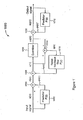
- FIG. 1 is a block diagram of a first conventional NFC structure or codec 1000.
- Codec 1000 includes the following functional elements: a first predictor 1002 (also referred to as predictor P(z)); a first combiner or adder 1004; a second combiner or adder 1006; a quantizer 1008; a third combiner or adder 1010; a second predictor 1012 (also referred to as a predictor P(z)); a fourth combiner 1014; and a noise feedback filter 1016 (also referred to as a filter F(z)).
- a first predictor 1002 also referred to as predictor P(z)
- a first combiner or adder 1004 also referred to as predictor P(z)
- a second combiner or adder 1006 a quantizer 1008
- a third combiner or adder 1010 a second predictor 1012 (also referred to as a predictor P(z)); a fourth combiner 1014; and a noise feedback filter 10
- Codec 1000 encodes a sampled input speech or audio signal s(n) to produce a coded speech signal, and then decodes the coded speech signal to produce a reconstructed speech signal sq(n), representative of the input speech signal s(n).
- An encoder portion of codec 1000 operates as follows. Sampled input speech or audio signal s(n) is provided to a first input of combiner 1004, and to an input of predictor 1002.
- Predictor 1002 makes a prediction of current speech signal s(n) values (e.g., samples) based on past values of the speech signal to produce a predicted signal ps(n).
- Predictor 1002 provides predicted speech signal ps(n) to a second input of combiner 1004.
- Combiner 1004 combines signals s(n) and ps(n) to produce a prediction residual signal d(n).
- Combiner 1006 combines residual signal d(n) with a noise feedback signal fq(n) to produce a quantizer input signal u(n).
- Quantizer 1008 quantizes input signal u(n) to produce a quantized signal uq(n).
- Combiner 1014 combines (that is, differences) signals u(n) and uq(n) to produce a quantization error or noise signal q(n) associated with the quantized signal uq(n).
- Filter 1016 filters noise signal q(n) to produce feedback noise signal fq(n).
- a decoder portion of codec 1000 operates as follows. Exiting quantizer 1008, combiner 1010 combines quantizer output signal uq(n) with a prediction ps(n)' of input speech signal s(n) to produce reconstructed output speech signal sq(n). Predictor 1012 predicts input speech signal s(n) to produce predicted speech signal ps(n)', based on past samples of output speech signal sq(n).
- the predictor P(z) (1002 or 1012) has a transfer function of where M is the predictor order and a i is the i -th predictor coefficient.
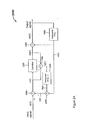
- FIG. 2 is a block diagram of a second conventional NFC structure or codec 2000.
- Codec 2000 includes the following functional elements: a first combiner or adder 2004; a second combiner or adder 2006; a quantizer 2008; a third combiner or adder 2010; a predictor 2012 (also referred to as a predictor P(z)); a fourth combiner 2014; and a noise feedback filter 2016 (also referred to as a filter N(z)-1).
- Codec 2000 encodes a sampled input speech signal s(n) to produce a coded speech signal, and then decodes the coded speech signal to produce a reconstructed speech signal sq(n), representative of the input speech signal s(n).
- Codec 2000 operates as follows. A sampled input speech or audio signal s(n) is provided to a first input of combiner 2004. A feedback signal x(n) is provided to a second input of combiner 2004. Combiner 2004 combines signals s(n) and x(n) to produce a quantizer input signal u(n).
- Quantizer 2008 quantizes input signal u(n) to produce a quantized signal uq(n) (also referred to as a quantizer output signal uq(n)).
- Combiner 2014 combines (that is, differences) signals u(n) and uq(n) to produce a quantization error or noise signal q(n) associated with the quantized signal uq(n).
- Filter 2016 filters noise signal q(n) to produce feedback noise signal fq(n).
- Combiner 2006 combines feedback noise signal fq(n) with a predicted signal ps(n) (i.e., a prediction of input speech signal s(n)) to produce feedback signal x(n).
- combiner 2010 combines quantizer output signal uq(n) with prediction or predicted signal ps(n) to produce reconstructed output speech signal sq(n).
- Predictor 2012 predicts input speech signal s(n) (to produce predicted speech signal ps(n)) based on past samples of output speech signal sq(n). Thus, predictor 2012 is included in the encoder and decoder portions of codec 2000.
- Codec structure 2000 was proposed by J. D. Makhoul and M. Berouti in "Adaptive Noise Spectral Shaping and Entropy Coding in Predictive Coding of Speech," IEEE Transactions on Acoustics , Speech, and Signal Processing , pp. 63-73, February 1979.
- This equivalent, known NFC codec structure 2000 has at least two advantages over codec 1000. First, only one predictor P(z) (2012) is used in the structure. Second, if N(z) is the filter whose frequency response corresponds to the desired noise spectral shape, this codec structure 2000 allows us to use [ N(z) - 1] directly as the noise feedback filter 2016. Makhoul and Berouti showed in their 1979 paper that very good perceptual speech quality can be obtained by choosing N(z) to be a simple second-order finite-impulse-response (FIR) filter.
- FIR finite-impulse-response
- Figs 1 and 2 can each be viewed as a predictive codec with an additional noise feedback loop.
- a noise feedback loop is added to the structure of an "open-loop DPCM" codec, where the predictor in the encoder uses unquantized original input signal as its input.
- Fig. 2 on the other hand, a noise feedback loop is added to the structure of a "closed-loop DPCM” codec, where the predictor in the encoder uses the quantized signal as its input.
- the codec structures in Fig.1 and Fig.2 are conceptually very similar.
- a first approach is to combine a short-term predictor and a long-term predictor into a single composite short-term and long-term predictor, and then re-use the general structure of codec 1000 in FIG. 1 or that of codec 2000 in FIG. 2 to construct an improved codec corresponding to the general structure of codec 1000 and an improved codec corresponding to the general structure of codec 2000.
- the feedback loop to the right of the symbol uq(n) that includes the adder 1010 and the predictor loop (including predictor 1012) is often called a synthesis filter, and has a transfer function of 1/[1 - P(z) ].
- the decoder has two such synthesis filters cascaded: one with the short-term predictor and the other with the long-term predictor in the feedback loop.
- Ps(z) and Pl(z) be the transfer functions of the short-term predictor and the long-term predictor, respectively.
- both short-term noise spectral shaping and long-term spectral shaping are achieved, and they can be individually controlled by the parameters ⁇ and ⁇ , respectively.
- FIG. 1A is a block diagram of an example NFC structure or codec 1050 using composite short-term and long-term predictors P'(z) and a composite short-term and long-term noise feedback filter F' (z), according to a first embodiment of the present invention.
- Codec 1050 reuses the general structure of known codec 1000 in FIG. 1, but replaces the predictors P(z) and filter of codec 1000 F(z) with the composite predictors P'(z) and the composite filter F'(z), as is further described below.
- first composite short-term and long-term predictor 1052 also referred to as a composite predictor P'(z)
- first combiner or adder 1054 also referred to as a composite predictor P'(z)
- second combiner or adder 1056 ; a quantizer 1058;
- third combiner or adder 1060 a second composite short-term and long-term predictor 1062 (also referred to as a composite predictor P'(z)); a fourth combiner 1064; and a composite short-term and long-term noise feedback filter 1066 (also referred to as a filter F'(z)).
- the functional elements or blocks of codec 1050 listed above are arranged similarly to the corresponding blocks of codec 1000 (described above in connection with FIG. 1) having reference numerals decreased by "50.” Accordingly, signal flow between the functional blocks of codec 1050 is similar to signal flow between the corresponding blocks of codec 1000.
- Codec 1050 encodes a sampled input speech signal s(n) to produce a coded speech signal, and then decodes the coded speech signal to produce a reconstructed speech signal sq(n), representative of the input speech signal s(n).
- An encoder portion of codec 1050 operates in the following exemplary manner.
- Composite predictor 1052 short-term and long-term predicts input speech signal s(n) to produce a short-term and long-term predicted speech signal ps(n).
- Combiner 1054 combines short-term and long-term predicted signal ps(n) with speech signal s(n) to produce a prediction residual signal d(n).
- Combiner 1056 combines residual signal d(n) with a short-term and long-term filtered, noise feedback signal fq(n) to produce a quantizer input signal u(n).
- Quantizer 1058 quantizes input signal u(n) to produce a quantized signal uq(n) (also referred to as a quantizer output signal) associated with a quantization noise or error signal q(n).
- Combiner 1064 combines (that is, differences) signals u(n) and uq(n) to produce the quantization error or noise signal q(n).
- Composite filter 1066 short-term and long-term filters noise signal q(n) to produce short-term and long-term filtered, feedback noise signal fq(n).
- combiner 1064, composite short-term and long-term filter 1066, and combiner 1056 together form a noise feedback loop around quantizer 1058.
- This noise feedback loop spectrally shapes the coding noise associated with codec 1050, in accordance with the composite filter, to follow, for example, the short-term and long-term spectral characteristics of input speech signal s(n).
- a decoder portion of coder 1050 operates in the following exemplary manner.
- combiner 1060 combines quantizer output signal uq(n) with a short-term and long-term prediction ps(n)' of input speech signal s(n) to produce a quantized output speech signal sq(n).
- Composite predictor 1062 short-term and long-term predicts input speech signal s(n) (to produce short-term and long-term predicted signal ps(n)') based on output signal sq(n).
- a second embodiment of the present invention can be constructed based on the general coding structure of codec 2000 in FIG. 2.
- a suitable composite noise feedback filter N'(z) - 1 (replacing filter 2016) such that it includes the effects of both short-term and long-term noise spectral shaping.
- N'(z) can be chosen to' contain two FIR filters in cascade: a short-term filter to control the envelope of the noise spectrum, while another, long-term filter, controls the harmonic structure of the noise spectrum.
- FIG. 2A is a block diagram of an example NFC structure or codec 2050 using a composite short-term and long-term predictor P'(z) and a composite short-term and long-term noise feedback filter N'(z)-1, according to a second embodiment of the present invention.
- Codec 2050 includes the following functional elements: a first combiner or adder 2054; a second combiner or adder 2056; a quantizer 2058; a third combiner or adder 2060; a composite short-term and long-term predictor 2062 (also referred to as a predictor P'(z)); a fourth combiner 2064; and a noise feedback filter 2066 (also referred to as a filter N'(z)-1).
- the functional elements or blocks of codec 2050 listed above are arranged similarly to the corresponding blocks of codec 2000 (described above in connection with FIG. 2) having reference numerals decreased by "50.” Accordingly, signal flow between the functional blocks of codec 2050 is similar to signal flow between the corresponding blocks of codec 2000.
- Codec 2050 operates in the following exemplary manner.
- Combiner 2054 combines a sampled input speech or audio signal s(n) with a feedback signal x(n) to produce a quantizer input signal u(n).
- Quantizer 2058 quantizes input signal u(n) to produce a quantized signal uq(n) associated with a quantization noise or error signal q(n).
- Combiner 2064 combines (that is, differences) signals u(n) and uq(n) to produce quantization error or noise signal q(n).
- Composite filter 2066 concurrently long-term and short-term filters noise signal q(n) to produce short-term and long-term filtered, feedback noise signal fq(n).
- Combiner 2056 combines short-term and long-term filtered, feedback noise signal fq(n) with a short-term and long-term prediction s(n) of input signal s(n) to produce feedback signal x(n).
- codec 2050 combiner 2064, composite short-term and long-term filter 2066, and combiner 2056 together form a noise feedback loop around quantizer 2058.
- This noise feedback loop spectrally shapes the coding noise associated with codec 2050 in accordance with the composite filter, to follow, for example, the short-term and long-term spectral characteristics of input speech signal s(n).
- combiner 2060 combines quantizer output signal uq(n) with the short-term and long-term predicted signal ps(n)' to produce a reconstructed output speech signal sq(n).
- Composite predictor 2062 short-term an long-term predicts input speech signal s(n) (to produce short-term and long-term predicted signal ps(n)) based on reconstructed output speech signal sq(n).
- the first approach for two-stage NFC described above achieves the goal by re-using the general codec structure of conventional single-stage noise feedback coding (for example, by re-using the structures of codecs 1000 and 2000) but combining what are conventionally separate short-term and long-term predictors into a single composite short-term and long-term predictor.
- a second preferred approach, described below, allows separate short-term and long-term predictors to be used, but requires a modification of the conventional codec structures 1000 and 2000 of Figs. 1 and 2.
- the key lies in recognizing that the quantizer block in Figs. 1 and 2 can be replaced by a coding system based on long-term prediction. Illustrations of this concept are provided below.
- FIG. 3 shows a codec structure where the quantizer block 1008 in FIG. I has been replaced by a DPCM-type structure based on long-term prediction (enclosed by the dashed box and labeled as Q' in FIG. 3).
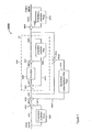
- FIG. 3 is a block diagram of a first exemplary arrangement of an example NFC structure or codec 3000, according to a third embodiment of the present invention.
- Codec 3000 includes the following functional elements: a first short-term predictor 3002 (also referred to as a short-term predictor Ps(z)); a first combiner or adder 3004; a second combiner or adder 3006; predictive quantizer 3008 (also referred to as predictive quantizer Q'); a third combiner or adder 3010; a second short-term predictor 3012 (also referred to as a short-term predictor Ps(z)); a fourth combiner 3014; and a short-term noise feedback filter 3016 (also referred to as a short-term noise feedback filter Fs(z)).
- a first short-term predictor 3002 also referred to as a short-term predictor Ps(z)
- a first combiner or adder 3004 also referred to as a short-term predictor Ps(z)
- predictive quantizer 3008 also referred to as predictive quantizer Q'
- a third combiner or adder 3010 a second short-term predictor 3012
- Predictive quantizer Q' includes a first combiner 3024, either a scalar or a vector quantizer 3028, a second combiner 3030, and a long-term predictor 3034 (also referred to as a long-term predictor (Pl(z)).
- Codec 3000 encodes a sampled input speech signal s(n) to produce a coded speech signal, and then decodes the coded speech signal to produce a reconstructed output speech signal sq(n), representative of the input speech signal s(n).
- Codec 3000 operates in the following exemplary manner. First, a sampled input speech or audio signal s(n) is provided to a first input of combiner 3004, and to an input of predictor 3002. Predictor 3002 makes a short-term prediction of input speech signal s(n) based on past samples thereof to produce a predicted input speech signal ps(n).
- Predictor 3002 provides predicted input speech signal ps(n) to a second input of combiner 3004.
- Combiner 3004 combines signals s(n) and ps(n) to produce a prediction residual signal d(n).
- Combiner 3006 combines residual signal d(n) with a first noise feedback signal fqs(n) to produce a predictive quantizer input signal v(n).
- Predictive quantizer 3008 predictively quantizes input signal v(n) to produce a predictively quantized output signal vq(n) (also referred to as a predictive quantizer output signal vq(n)) associated with a predictive noise or error signal qs(n).
- Combiner 3014 combines (that is, differences) signals v(n) and vq(n) to produce the predictive quantization error or noise signal qs(n).
- Short-term filter 3016 short-term filters predictive quantization noise signal q(n) to produce the feedback noise signal fqs(n).
- Noise Feedback (NF) codec 3000 includes an outer NF loop around predictive quantizer 3008, comprising combiner 3014, short-term noise filter 3016, and combiner 3006. This outer NF loop spectrally shapes the coding noise associated with codec 3000 in accordance with filter 3016, to follow, for example, the short-term spectral characteristics of input speech signal s(n).
- Predictive quantizer 3008 operates within the outer NF loop mentioned above to predictively quantize predictive quantizer input signal v(n) in the following exemplary manner.
- Predictor 3034 long-term predicts (i.e., makes a long-term prediction of) predictive quantizer input signal v(n) to produce a predicted, predictive quantizer input signal pv(n).
- Combiner 3024 combines signal pv(n) with predictive quantizer input signal v(n) to produce a quantizer input signal u(n).
- Quantizer 3028 quantizes quantizer input signal u(n) using a scalar or vector quantizing technique, to produce a quantizer output signal uq(n).
- Combiner 3030 combines quantizer output signal uq(n) with signal pv(n) to produce predictively quantized output signal vq(n).
- combiner 3010 combines predictive quantizer output signal vq(n) with a prediction ps(n)' of input speech signal s(n) to produce output speech signal sq(n).
- Predictor 3012 short-term predicts (i.e., makes a short-term prediction of) input speech signal s(n) to produce signal ps(n)', based on output speech signal sq(n).
- predictors 3002, 3012 are short-term predictors and NF filter 3016 is a short-term noise filter, while predictor 3034 is a long-term predictor.
- predictors 3002, 3012 are long-term predictors and NF filter 3016 is a long-term filter, while predictor 3034 is a short-term predictor.
- the outer NF loop in this alternative arrangement spectrally shapes the coding noise associated with codec 3000 in accordance with filter 3016, to follow, for example, the long-term spectral characteristics of input speech signal s(n).
- the DPCM structure inside the Q' dashed box (3008) does not perform long-term noise spectral shaping. If everything inside the Q' dashed box (3008) is treated as a black box, then for an observer outside of the box, the replacement of a direct quantizer (for example, quantizer 1008) by a long-term-prediction-based DPCM structure (that is, predictive quantizer Q' (3008)) is an advantageous way to improve the quantizer performance.
- the codec structure of codec 3000 in FIG. 3 will achieve the advantage of a lower coding noise, while maintaining the same kind of noise spectral envelope.
- the system 3000 in FIG. 3 is good enough for some applications when the bit rate is high enough and it is simple, because it avoids the additional complexity associated with long-term noise spectral shaping.
- predictive quantizer Q' (3008) of codec 3000 in FIG. 3 can be replaced by the complete NFC structure of codec 1000 in FIG. 1.
- a resulting example "nested” or “layered” two-stage NFC codec structure 4000 is depicted in FIG. 4, and described below.
- FIG. 4 is a block diagram of a first exemplary arrangement of the example nested two-stage NF coding structure or codec 4000, according to a fourth embodiment of the present invention.
- Codec 4000 includes the following functional elements: a first short-term predictor 4002 (also referred to as a short-term predictor Ps(z)); a first combiner or adder 4004; a second combiner or adder 4006; a predictive quantizer 4008 (also referred to as a predictive quantizer Q"); a third combiner or adder 4010; a second short-term predictor 4012 (also referred to as a short-term predictor Ps(z)); a fourth combiner 4014; and a short-term noise feedback filter 4016 (also referred to as a short-term noise feedback filter Fs(z)).
- a first short-term predictor 4002 also referred to as a short-term predictor Ps(z)
- a first combiner or adder 4004 also a second
- Predictive quantizer Q includes a first long-term predictor 4022 (also referred to as a long-term predictor Pl(z)), a first combiner 4024, either a scalar or a vector quantizer 4028, a second combiner 4030, a second long-term predictor 4034 (also referred to as a long-term predictor (Pl(z)), a second combiner or adder 4036, and a long-term filter 4038 (also referred to as a long-term filter Fl(z)).
- Codec 4000 encodes a sampled input speech signal s(n) to produce a coded speech signal, and then decodes the coded speech signal to produce a reconstructed output speech signal sq(n), representative of the input speech signal s(n).
- predictors 4002 and 4012, combiners 4004, 4006, and 4010, and noise filter 4016 operate similarly to corresponding elements described above in connection with FIG. 3 having reference numerals decreased by "1000". Therefore, NF codec 4000 includes an outer or first stage NF loop comprising combiner 4014, short-term noise filter 4016, and combiner 4006. This outer NF loop spectrally shapes the coding noise associated with codec 4000 in accordance with filter 4016, to follow, for example, the short-term spectral characteristics of input speech signal s(n).
- Predictive quantizer Q" (4008) operates within the outer NF loop mentioned above to predictively quantize predictive quantizer input signal v(n) to produce a predictively quantized output signal vq(n) (also referred to as a predictive quantizer output signal vq(n)) in the following exemplary manner.
- predictive quantizer Q has a structure corresponding to the basic NFC structure of codec 1000 depicted in FIG. 1.
- predictor 4022 long-term predicts predictive quantizer input signal v(n) to produce a predicted version pv(n) thereof.
- Combiner 4024 combines signals v(n) and pv(n) to produce an intermediate result signal i(n).
- Combiner 4026 combines intermediate result signal i(n) with a second noise feedback signal fq(n) to produce a quantizer input signal u(n).
- Quantizer 4028 quantizes input signal u(n) to produce a quantized output signal uq(n) (or quantizer output signal uq(n)) associated with a quantization error or noise signal q(n).
- Combiner 4036 combines (differences) signals u(n) and uq(n) to produce the quantization noise signal q(n).
- Long-term filter 4038 long-term filters the noise signal q(n) to produce feedback noise signal fq(n).
- combiner 4036, long-term filter 4038 and combiner 4026 form an inner or second stage NF loop nested within the outer NF loop.
- This inner NF loop spectrally shapes the coding noise associated with codec 4000 in accordance with filter 4038, to follow, for example, the long-term spectral characteristics of input speech signal s(n).
- combiner 4030 combines quantizer output signal uq(n) with a prediction pv(n)' of predictive quantizer input signal v(n).
- Long-term predictor 4034 long-term predicts signal v(n) (to produce predicted signal pv(n)') based on signal vq(n).
- predictive quantizer Q (4008), predictively quantized signal vq(n) is combined with a prediction ps(n)' of input speech signal s(n) to produce reconstructed speech signal sq(n).
- Predictor 4012 short term predicts input speech signal s(n) (to produce predicted signal ps(n)') based on reconstructed speech signal sq(n).
- predictors 4002 and 4012 are short-term predictors and NF filter 4016 is a short-term noise filter, while predictors 4022, 4034 are long-term predictors and noise filter 4038 is a long-term noise filter.
- predictors 4002, 4012 are long-term predictors and NF filter 4016 is a long-term noise filter (to spectrally shape the coding noise to follow, for example, the long-term characteristic of the input speech signal s(n)), while predictors 4022, 4034 are short-term predictors and noise filter 4038 is a short-term noise filter (to spectrally shape the coding noise to follow, for example, the short-term characteristic of the input speech signal s(n)).
- the nested two-stage NFC codec structure 4000 in FIG. 4 indeed performs both short-term and long-term noise spectral shaping, in addition to short-term and long-term prediction.
- nested two-stage NFC structure 4000 as shown in FIG. 4 is that it completely decouples long-term noise feedback coding from short-term noise feedback coding. This allows us to use different codec structures for long-term NFC and short-term NFC, as the following examples illustrate.
- predictive quantizer Q 4008 of codec 4000 in FIG. 4 can be replaced by codec 2000 in FIG. 2, thus constructing another example nested two-stage NFC structure 5000, depicted in FIG. 5 and described below.
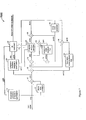
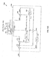
- FIG. 5 is a block diagram of a first exemplary arrangement of the example nested two-stage NFC structure or codec 5000, according to a fifth embodiment of the present invention.
- Codec 5000 includes the following functional elements: a first short-term predictor 5002 (also referred to as a short-term predictor Ps(z)); a first combiner or adder 5004; a second combiner or adder 5006; a predictive quantizer 5008 (also referred to as a predictive quantizer Q"'); a third combiner or adder 5010; a second short-term predictor 5012 (also referred to as a short-term predictor Ps(z)); a fourth combiner 5014; and a short-term noise feedback filter 5016 (also referred to as a short-term noise feedback filter Fs(z)).
- a first short-term predictor 5002 also referred to as a short-term predictor Ps(z)
- a first combiner or adder 5004 also referred to as
- Predictive quantizer Q"' includes a first combiner 5024, a second combiner 5026, either a scalar or a vector quantizer 5028, a third combiner 5030, a long-term predictor 5034 (also referred to as a long-term predictor (Pl(z)), a fourth combiner 5036, and a long-term filter 5038 (also referred to as a long-term filter Nl(z)-1).
- Codec 5000 encodes a sampled input speech signal s(n) to produce a coded speech signal, and then decodes the coded speech signal to produce a reconstructed output speech signal sq(n), representative of the input speech signal s(n).
- predictors 5002 and 5012, combiners 5004, 5006, and 5010, and noise filter 5016 operate similarly to corresponding elements described above in connection with FIG. 3 having reference numerals decreased by "2000". Therefore, NF codec 5000 includes an outer or first stage NF loop comprising combiner 5014, short-term noise filter 5016, and combiner 5006. This outer NF loop spectrally shapes the coding noise associated with codec 5000 according to filter 5016, to follow, for example, the short-term spectral characteristics of input speech signal s(n).
- Predictive quantizer 5008 has a structure similar to the structure of NF codec 2000 described above in connection with FIG. 2.
- Predictive quantizer Q''' (5008) operates within the outer NF loop mentioned above to predictively quantize a predictive quantizer input signal v(n) to produce a predictively quantized output signal vq(n) (also referred to as predicted quantizer output signal vq(n)) in the following exemplary manner.
- Predictor 5034 long-term predicts input signal v(n) based on output signal vq(n), to produce a predicted signal pv(n) (i.e., representing a prediction of signal v(n)).
- Combiners 5026 and 5024 collectively combine signal pv(n) with a noise feedback signal fq(n) and with input signal v(n) to produce a quantizer input signal u(n).
- Quantizer 5028 quantizes input signal u(n) to produce a quantized output signal uq(n) (also referred to as a quantizer output signal uq(n)) associated with a quantization error or noise signal q(n).
- Combiner 5036 combines (i.e., differences) signals u(n) and uq(n) to produce the quantization noise signal q(n).
- Filter 5038 long-term filters the noise signal q(n) to produce feedback noise signal fq(n).
- combiner 5036, long-term filter 5038 and combiners 5026 and 5024 form an inner or second stage NF loop nested within the outer NF loop.
- This inner NF loop spectrally shapes the coding noise associated with codec 5000 in accordance with filter 5038, to follow, for example, the long-term spectral characteristics of input speech signal s(n).
- predictors 5002, 5012 are long-term predictors and NF filter 5016 is a long-term noise filter (to spectrally shape the coding noise to follow, for example, the long-term characteristic of the input speech signal s(n)), while predictor 5034 is a short-term predictor and noise filter 5038 is a short-term noise filter (to spectrally shape the coding noise to follow, for example, the short-term characteristic of the input speech signal s(n)).
- FIG. 5A is a block diagram of an alternative but mathematically equivalent signal combining arrangement 5050 corresponding to the combining arrangement including combiners 5024 and 5026 of FIG. 5.
- Combining arrangement 5050 includes a first combiner 5024' and a second combiner 5026'.
- Combiner 5024' receives predictive quantizer input signal v(n) and predicted signal pv(n) directly from predictor 5034.
- Combiner 5024' combines these two signals to produce an intermediate signal i(n)'.
- Combiner 5026' receives intermediate signal i(n)' and feedback noise signal fq(n) directly from noise filter 5038.
- Combiner 5026' combines these two received signals to produce quantizer input signal u(n). Therefore, equivalent combining arrangement 5050 is similar to the combining arrangement including combiners 5024 and 5026 of FIG. 5.
- the outer layer NFC structure in FIG. 5 i.e., all of the functional blocks outside of predictive quantizer Q''' (5008)
- the NFC structure 2000 in FIG. 2 can be replaced by the NFC structure 2000 in FIG. 2, thereby constructing a further codec structure 6000, depicted in FIG. 6 and described below.
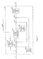
- FIG. 6 is a block diagram of a first exemplary arrangement of the example nested two-stage NF coding structure or codec 6000, according to a sixth embodiment of the present invention.
- Codec 6000 includes the following functional elements: a first combiner 6004; a second combiner 6006; predictive quantizer Q''' (5008) described above in connection with FIG. 5; a third combiner or adder 6010; a short-term predictor 6012 (also referred to as a short-term predictor Ps(z)); a fourth combiner 6014; and a short-term noise feedback filter 6016 (also referred to as a short-term noise feedback filter Ns(z)-1).
- Codec 6000 encodes a sampled input speech signal s(n) to produce a coded speech signal, and then decodes the coded speech signal to produce a reconstructed output speech signal sq(n), representative of the input speech signal s(n).
- a combining arrangement including combiners 6004 and 6006 can be replaced by an equivalent combining arrangement similar to combining arrangement 5050 discussed in connection with FIG. 5A, whereby a combiner 6004' (not shown) combines signals s(n) and ps(n)' to produce a residual signal d(n) (not shown), and then a combiner 6006' (also not shown) combines signals d(n) and fqs(n) to produce signal v(n).
- codec 6000 includes a predictive quantizer equivalent to predictive quantizer 5008 (described above in connection with FIG. 5, and depicted in FIG. 6 for descriptive convenience) to predictively quantize a predictive quantizer input signal v(n) to produce a quantized output signal vq(n). Accordingly, codec 6000 also includes a first stage or outer noise feedback loop to spectrally shape the coding noise to follow, for example, the short-term characteristic of the input speech signal s(n), and a second stage or inner noise feedback loop nested within the outer loop to spectrally shape the coding noise to follow, for example, the long-term characteristic of the input speech signal.
- predictor 6012 is a long-term predictor and NF filter 6016 is a long-term noise filter, while predictor 5034 is a short-term predictor and noise filter 5038 is a short-term noise filter.
- the short-term synthesis filter (including predictor 5012) to the right of the Q''' dashed box (5008) does not need to be implemented in the encoder (and all three decoders corresponding to FIGs. 4-6 need to implement it).
- the short-term analysis filter (including predictor 5002) to the left of the symbol d(n) needs to be implemented anyway even in FIG. 6 (although not shown there), because we are using d(n) to derive a weighted speech signal, which is then used for pitch estimation. Therefore, comparing the rest of the outer layer, FIG. 5 has only one short-term filter Fs(z) (5016) to implement, while FIG. 6 has two short-term filters.
- the outer layer of FIG. 5 has a lower complexity than the outer layer of FIG. 6.
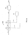
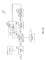
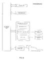
- FIG. 6A is an example method 6050 of coding a speech or audio signal using any one of the example codecs 3000, 4000, 5000, and 6000 described above.
- a predictor e.g., 3002 in FIG. 3, 4002 in FIG. 4, 5002 in FIG. 5 , or 6012 in FIG. 6 predicts an input speech or audio signal (e.g., s(n)) to produce a predicted speech signal (e.g., ps(n) or ps(n)').
- a combiner e.g., 3004, 4004, 5004, 6004/6006 or equivalents thereof combines the predicted speech signal (e.g., ps(n)) with the speech signal (e.g., s(n)) to produce a first residual signal (e.g., d(n)).
- a combiner e.g., 3006, 4006, 5006, 6004/6006 or equivalents thereof combines a first noise feedback signal (e.g., fqs(n)) with the first residual signal (e.g., d(n)) to produce a predictive quantizer input signal (e.g., v(n)).
- a predictive quantizer (e.g., Q', Q", or Q"') predictively quantizes the predictive quantizer input signal (e.g., v(n)) to produce a predictive quantizer output signal (e.g., vq(n)) associated with a predictive quantization noise (e.g., qs(n)).
- a filter e.g., 3016, 4016, or 5016 filters the predictive quantization noise (e.g., qs(n)) to produce the first noise feedback signal (e.g., fqs(n)).
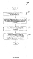
- FIG. 6B is a detailed method corresponding to predictive quantizing step 6064 described above.
- a predictor e.g., 3034, 4022, or 5034 predicts the predictive quantizer input signal (e.g., v(n)) to produce a predicted predictive quantizer input signal (e.g., pv(n)).
- a combiner e.g., 3024, 4024, 5024/5026 or an equivalent thereof, such as 5024'
- a combiner combines at least the predictive quantizer input signal (e.g., v(n)) with at least the first predicted predictive quantizer input signal (e.g., pv(n)) to produce a quantizer input signal (e.g., u(n)).
- the codec embodiments including an inner noise feedback loop use further combining logic (e.g., combiners 5026/5026' or 4026 or equivalents thereof)) to further combine a second noise feedback signal (e.g., fq(n)) with the predictive quantizer input signal (e.g., v(n)) and the first predicted predictive quantizer input signal (e.g., pv(n)), to produce the quantizer input signal (e.g., u(n)).
- further combining logic e.g., combiners 5026/5026' or 4026 or equivalents thereof
- a scalar or vector quantizer (e.g., 3028, 4028, or 5028) quantizes the input signal (e.g., u(n)) to produce a quantizer output signal (e.g., uq(n)).
- a filter e.g., 4038 or 5038 filters a quantization noise (e.g., q(n)) associated with the quantizer output signal (e.g., q(n)) to produce the second noise feedback signal (fq(n)).
- a quantization noise e.g., q(n)
- deriving logic e.g., 3034 and 3030 in FIG. 3, 4034 and 4030 in FIG. 4, and 5034 and 5030 in FIG. 5 derives the predictive quantizer output signal (e.g., vq(n)) based on the quantizer output signal (e.g., uq(n)).
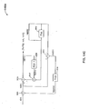
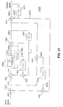
- FIG. 7 shows an example encoder 7000 of the preferred embodiment.
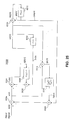
- FIG. 8 shows the corresponding decoder.
- the encoder structure 7000 in FIG. 7 is based on the structure of codec 5000 in FIG. 5.
- the short-term synthesis filter (including predictor 5012) in FIG. 5 does not need to be implemented in FIG. 7, since its output is not used by encoder 7000.
- These functional blocks also singularly and collectively referred to as "parameter deriving logic" adaptively analyze and quantize (and thereby derive) the coefficients of the short-term and long-term filters.
- FIG. 7 shows an example encoder 7000 of the preferred embodiment.
- FIG. 8 shows the corresponding decoder.
- the encoder structure 7000 in FIG. 7 is based on the structure of codec 5000 in FIG. 5.
- the short-term synthesis filter (including predictor 5012) in FIG. 5 does not need
- the decoder in FIG. 8 is essentially the same as the decoder of most other modern predictive codecs such as MPLPC and CELP. No postfilter is used in the decoder.
- Coder 7000 and coder 5000 of FIG. 5 have the following corresponding functional blocks: predictors 5002 and 5034 in FIG. 5 respectively correspond to predictors 40 and 60 in FIG. 7; combiners 5004, 5006, 5014, 5024, 5026, 5030 and 5036 in FIG. 5 respectively correspond to combiners 45, 55, 90, 75, 70, 85 and 80 in FIG. 7; filters 5016 and 5038 in FIG. 5 respectively correspond to filters 50 and 65 in FIG. 7; quantizer 5028 in FIG. 5 corresponds to quantizer 30 in FIG. 7; signals vq(n), pv(n), fqs(n), and fq(n) in FIG.
- codec 5000 respectively correspond to signals dq(n), ppv(n), stnf(n), and ltnf(n) in FIG. 7; signals sharing the same reference labels in FIG.5 and FIG. 7 also correspond to each other. Accordingly, the operation of codec 5000 described above in connection with FIG. 5 correspondingly applies to codec 7000 of FIG. 7.
- the input signal s(n) is buffered at block 10, which performs short-term linear predictive analysis and quantization to obtain the coefficients for the short-term predictor 40 and the short-term noise feedback filter 50.
- This block 10 is further expanded in FIG. 9.
- the processing blocks within FIG. 9 all employ well-known prior-art techniques.
- the input signal s(n) is buffered at block 11, where it is multiplied by an analysis window that is 20 ms in length.
- an analysis window that is 20 ms in length.
- the coding delay is not critical, then a frame size of 20 ms and a sub-frame size of 5 ms can be used, and the analysis window can be a symmetric window centered at the mid-point of the last sub-frame in the current frame.
- the coding delay we want the coding delay to be as small as possible; therefore, the frame size and the sub-frame size are both selected to be 5 ms, and no look ahead is allowed beyond the current frame. In this case, an asymmetric window is used.
- the "left window” is 17.5 ms long, and the “right window” is 2.5 ms long.
- the two parts of the window concatenate to give a total window length of 20 ms.
- the right window is given by
- the calculated autocorrelation coefficients are passed to block 12, which applies a Gaussian window to the autocorrelation coefficients to perform the well-known prior-art method of spectral smoothing.
- WNCF white noise correction factor
- the spectral smoothing technique smoothes out (widens) sharp resonance peaks in the frequency response of the short-term synthesis filter.
- the white noise correction adds a white noise floor to limit the spectral dynamic range. Both techniques help to reduce ill conditioning in the Levinson-Durbin recursion of block 13.
- the parameter ⁇ is chosen as 0.96852.
- Block 15 converts the ⁇ a i ⁇ coefficients to Line Spectrum Pair (LSP) coefficients ⁇ l i ⁇ , which are sometimes also referred to as Line Spectrum Frequencies (LSFs). Again, the operation of block 15 is a well-known prior-art procedure.
- LSP Line Spectrum Pair
- Block 16 quantizes and encodes the M LSP coefficients to a pre-determined number of bits.
- the output LSP quantizer index array LSPI is passed to the bit multiplexer (block 95), while the quantized LSP coefficients are passed to block 17.
- Many different kinds of LSP quantizers can be used in block 16.
- the quantization of LSP is based on inter-frame moving-average (MA) prediction and multi-stage vector quantization, similar to (but not the same as) the LSP quantizer used in the ITU-T Recommendation G.729.
- Block 16 is further expanded in FIG. 10. Except for the LSP quantizer index array LSPI, all other signal paths in FIG. 10 are for vectors of dimension M. Block 161 uses the unquantized LSP coefficient vector to calculate the weights to be used later in VQ codebook search with weighted mean-square error (WMSE) distortion criterion. The weights are determined as
- the i -th weight is the inverse of the distance between the i -th LSP coefficient and its nearest neighbor LSP coefficient. These weights are different from those used in G.729.
- Block 162 stores the long-term mean value of each of the M LSP coefficients, calculated off-line during codec design phase using a large training data file.
- Adder 163 subtracts the LSP mean vector from the unquantized LSP coefficient vector to get the mean-removed version of it.
- Block 164 is the inter-frame MA predictor for the LSP vector. In our preferred embodiment, the order of this MA predictor is 8. The 8 predictor coefficients are fixed and pre-designed off-line using a large training data file.
- this 8 th -order predictor covers a time span of 40 ms, the same as the time span covered by the 4 th -order MA predictor of LSP used in G.729, which has a frame size of 10 ms.
- Block 164 multiplies the 8 output vectors of the vector quantizer block 166 in the previous 8 frames by the 8 sets of 8 fixed MA predictor coefficients and sum up the result.
- the resulting weighted sum is the predicted vector, which is subtracted from the mean-removed unquantized LSP vector by adder 165.
- the two-stage vector quantizer block 166 then quantizes the resulting prediction error vector.
- the first-stage VQ inside block 166 uses a 7-bit codebook (128 codevectors).
- the second-stage VQ also uses a 7-bit codebook. This gives a total encoding rate of 14 bits/frame for the 8 LSP coefficients of the 16 kb/s narrowband codec.
- the second-stage VQ is a split VQ with a 3-5 split.
- the first three elements of the error vector of first-stage VQ are vector quantized using a 5-bit codebook, and the remaining 5 elements are vector quantized using another 5-bit codebook.
- both stages of VQ within block 166 use the WMSE distortion measure with the weights ⁇ w i ⁇ calculated by block 161.
- the codebook indices for the best matches in the two VQ stages form the output LSP index array LSPI , which is passed to the bit multiplexer block 95 in FIG. 7.
- the output vector of block 166 is used to update the memory of the inter-frame LSP predictor block 164.
- the predicted vector generated by block 164 and the LSP mean vector held by block 162 are added to the output vector of block 166, by adders 167 and 168, respectively.
- the output of adder 168 is the quantized and mean-restored LSP vector.
- Block 169 check for correct ordering in the quantized LSP coefficients, and restore correct ordering if necessary.
- the output of block 169 is the final set of quantized LSP coefficients ⁇ ⁇ .
- the quantized set of LSP coefficients ⁇ ⁇ which is determined once a frame, is used by block 17 to perform linear interpolation of LSP coefficients for each sub-frame within the current frame.
- the sub-frame size can stay at 5 ms, while the frame size can be 10 ms or 20 ms.
- the linear interpolation of LSP coefficients is a well-known prior art.
- the frame size is chosen to be 5 ms, the same as the sub-frame size. In this degenerate case, block 17 can be omitted. This is why it is shown in dashed box.
- Block 18 takes the set of interpolated LSP coefficients ⁇ l ' i ⁇ and converts it to the corresponding set of direct-form linear predictor coefficients ⁇ ⁇ for each sub-frame. Again, such a conversion from LSP coefficients to predictor coefficients is well known in the art. The resulting set of predictor coefficients ⁇ ⁇ are used to update the coefficients of the short-term predictor block 40 in FIG. 7.
- This bandwidth-expanded set of filter coefficients ⁇ a ' i ⁇ are used to update the coefficients of the short-term noise feedback filter block 50 in FIG. 7 and the coefficients of the weighted short-term synthesis filter block 21 in FIG. 11 (to be discussed later). This completes the description of short-term predictive analysis and quantization block 10 in FIG. 7.
- the short-term predictor block 40 predicts the input signal sample s(n) based on a linear combination of the preceding M samples.
- the adder 45 subtracts the resulting predicted value from s(n) to obtain the short-term prediction residual signal, or the difference signal, d(n) .
- the long-term predictive analysis and quantization block 20 uses the short-term prediction residual signal ⁇ d(n) ⁇ of the current sub-frame and its quantized version ⁇ dq(n) ⁇ in the previous sub-frames to determine the quantized values of the pitch period and the pitch predictor taps. This block 20 is further expanded in FIG. 11.
- the short-term prediction residual signal d(n) passes through the weighted short-term synthesis filter block 21, whose output is calculated as
- the signal dw(n) is basically a perceptually weighted version of the input signal s(n), just like what is done in CELP codecs.
- This dw(n) signal is passed through a low-pass filter block 22, which has a -3 dB cut off frequency at about 800 Hz.
- a 4 th -order elliptic filter is used for this purpose.
- Block 23 down-samples the low-pass filtered signal to a sampling rate of 2 kHz. This represents a 4:1 decimation for the 16 kb/s narrowband codec or 8:1 decimation for the 32 kb/s wideband codec.
- the first-stage pitch search block 24 uses the decimated 2 kHz sampled signal dwd(n) to find a "coarse pitch period", denoted as cpp in FIG. 11.
- Block 24 searches through the calculated ⁇ c(k) ⁇ array and identifies all positive local peaks in the ⁇ c(k) ⁇ sequence.
- K p denote the resulting set of indices k p where c ( k p ) is a positive local peak, and let the elements in K p be arranged in an ascending order.
- Block 25 takes cpp as its input and performs a second-stage pitch period search in the undecimated signal domain to get a refined pitch period pp.
- Block 25 maintains a signal buffer with a total of MAXPP + 1 + SFRSZ samples, where SFRSZ is the sub-frame size, which is 40 and 80 samples for narrowband and wideband codecs, respectively.
- the last SFRSZ samples of this buffer are populated with the open-loop short-term prediction residual signal d(n) in the current sub-frame.
- the first MAXPP + 1 samples are populated with the MAXPP + 1 samples of quantized version of d(n), denoted as dq(n) , immediately preceding the current sub-frame.
- block 25 calculates the following correlation and energy terms in the undecimated dq(n) signal domain for time lags k within the search range [ lb , ub ].
- the time lag k ⁇ [ lb,ub ] that maximizes the ratio ( k )/ ( k ) is chosen as the final refined pitch period. That is,
- the refined pitch period pp is encoded into 7 bits or 8 bits, without any distortion.
- Block 25 also calculates ppt 1, the optimal tap weight for a single-tap pitch predictor, as follows
- Block 27 calculates the long-term noise feedback filter coefficient ⁇ as follows.
- Pitch predictor taps quantizer block 26 quantizes the three pitch predictor taps to 5 bits using vector quantization. Rather than minimizing the mean-square error of the three taps as in conventional VQ codebook search, block 26 finds from the VQ codebook the set of candidate pitch predictor taps that minimizes the pitch prediction residual energy in the current sub-frame. Using the same dq(n) buffer and time index convention as in block 25, and denoting the set of three taps corresponding to the j- th codevector as ⁇ b j 1 , b j 2 , b j 3 ⁇ , we can express such pitch prediction residual energy as
- the codebook index j* that maximizes such an inner product also minimizes the pitch prediction residual energy E j .
- the output pitch predictor taps index PPTI is chosen as
- the corresponding vector of three quantized pitch predictor taps is obtained by multiplying the first three elements of the selected codevector x j* by 0.5.
- block 28 calculates the open-loop pitch prediction residual signal e(n) as follows.
- the open-loop pitch prediction residual signal e(n) is used to calculate the residual gain. This is done inside the prediction residual quantizer block 30 in FIG. 7. Block 30 is further expanded in FIG. 12.
- the first log-gain is calculated as and the second log-gain is calculated as
- gain frame to refer to the time interval over which a residual gain is calculated.
- the gain frame size is SFRSZ for the narrowband codec and SFRSZ / 2 for the wideband codec. All the operations in FIG. 12 are done on a once-per-gain-frame basis.
- the long-term mean value of the log-gain is calculated off-line and stored in block 302.
- the adder 303 subtracts this long-term mean value from the output log-gain of block 301 to get the mean-removed version of the log-gain.
- the MA log-gain predictor block 304 is an FIR filter, with order 8 for the narrowband codec and order 16 for the wideband codec. In either case, the time span covered by the log-gain predictor is 40 ms.
- the coefficients of this log-gain predictor are pre-determined off-line and held fixed.
- the adder 305 subtracts the output of block 304, which is the predicted log-gain, from the mean-removed log-gain.
- the scalar quantizer block 306 quantizes the resulting log-gain prediction residual.
- the narrowband codec uses a 4-bit quantizer, while the wideband codec uses a 5-bit quantizer here.
- the gain quantizer codebook index GI is passed to the bit multiplexer block 95 of FIG. 7.
- the quantized version of the log-gain prediction residual is passed to block 304 to update the MA log-gain predictor memory.
- the adder 307 adds the predicted log-gain to the quantized log-gain prediction residual to get the quantized version of the mean-removed log-gain.
- the adder 308 then adds the log-gain mean value to get the quantized log-gain, denoted as qlg .
- Block 310 scales the residual quantizer codebook. That is, it multiplies all entries in the residual quantizer codebook by g .
- the resulting scaled codebook is then used by block 311 to perform residual quantizer codebook search.
- the prediction residual quantizer in the current invention of TSNFC can be either a scalar quantizer or a vector quantizer.
- a scalar quantizer gives a lower codec complexity at the expense of lower output quality.
- a vector quantizer improves the output quality but gives a higher codec complexity.
- a scalar quantizer is a suitable choice for applications that demand very low codec complexity but can tolerate higher bit rates. For other applications that do not require very low codec complexity, a vector quantizer is more suitable since it gives better coding efficiency than a scalar quantizer.
- the encoder structure of FIG. 7 is directly used as is, and blocks 50 through 90 operate on a sample-by-sample basis.
- the short-term noise feedback filter block 50 of FIG. 7 uses its filter memory to calculate the current sample of the short-term noise feedback signal stnf(n) as follows.
- the adder 55 adds stnf(n) to the short-term prediction residual d(n) to get v(n).
- v ( n ) d ( n ) + stnf ( n )
- Block 311 of FIG. 12 quantizes u(n) by simply performing the codebook search of a conventional scalar quantizer. It takes the current sample of the unquantized signal u(n), find the nearest neighbor from the scaled codebook provided by block 310, passes the corresponding codebook index CI to the bit multiplexer block 95 of FIG. 7, and passes the quantized value uq(n) to the adders 80 and 85 of FIG. 7.
- This q(n) sample is passed to block 65 to update the filter memory of the long-term noise feedback filter.
- the adder 85 adds ppv(n) to uq(n) to get dq(n), the quantized version of the current sample of the short-term prediction residual.
- dq ( n ) uq ( n ) + ppv ( n )
- This dq(n) sample is passed to block 60 to update the filter memory of the long-term predictor.
- the encoder structure of FIG. 7 cannot be used directly as is.
- An alternative approach and alternative structures need to be used. To see this, consider a conventional vector quantizer with a vector dimension K . Normally, an input vector is presented to the vector quantizer, and the vector quantizer searches through all codevectors in its codebook to find the nearest neighbor to the input vector. The winning codevector is the VQ output vector, and the corresponding address of that codevector is the quantizer out codebook index. If such a conventional VQ scheme is to be used with the codec structure in FIG. 7, then we need to determine K samples of the quantizer input u(n) at a time.
- Determining the first sample of u(n) in the VQ input vector is not a problem, as we have already shown how to do that in the last section.
- the second through the K -th samples of the VQ input vector cannot be determined, because they depend on the first through the ( K - 1)-th samples of the VQ output vector of the signal uq(n) , which have not been determined yet.
- the present invention avoids this chicken-and-egg problem by modifying the VQ codebook search procedure, as described below beginning with reference to FIG. 13A.
- FIG. 13A is a block diagram of an example Noise Feedback Coding (NFC) system 1300 for searching through N VQ codevectors, stored in a scaled VQ codebook 5028a, for a preferred one of the N VQ codevectors to be used for coding a speech or audio signal s(n).
- System 1300 includes scaled VQ codebook 5028a including a VQ codebook 1302 and a gain scaling unit 1304.
- Scaled VQ codebook 5028a corresponds to quantizer 3028, 4028, 5028, or 30, described above in connection with FIGs 3, 4, 5, or 7, respectively.
- VQ codebook 1302 includes N VQ codevectors.
- VQ codebook 1302 provides each of the N VQ codevectors stored in the codebook to gain scaling unit 1304.
- Gain scaling unit 1304 scales the codevectors, and provides scaled codevectors to an output of scaled VQ codebook 5028a.
- Symbol g(n) represents the quantized residual gain in the linear domain, as calculated in previous sections.
- the combination of VQ codebook 1302 and gain scaling unit 1304 (also labeled g(n)) is equivalent to a scaled VQ codebook.
- System 1300 further includes predictor logic unit 1306 (also referred to as a predictor 1306), an input vector deriver 1308, an error energy calculator 1310, a preferred codevector selector 1312, and a predictor/filter restorer 1314.
- Predictor 1306 includes combining and predicting logic.
- Input vector deriver 1308 includes combining, filtering, and predicting logic, corresponding to such logic used in codecs 3000, 4000, 5000, 6000, and 7000, for example, as will be further described below.
- the logic used in predictor 1306, input vector deriver 1308, and quantizer 1508a operates sample-by-sample in the same manner as described above in connection with codecs 3000-7000.
- a “vector” as used herein refers to a group of samples. It is to be understood that the VQ systems and methods described below process each of the samples in a vector (that is, in a group of samples) one sample at a time. For example, a filter filters an input vector in the following manner: a first sample of the input vector is applied to an input of the filter; the filter processes the first sample of the vector to produce a first sample of an output vector corresponding to the first sample of the input vector; and the process repeats for each of the next sequential samples of the input vector until there are no input vector samples left, whereby the filter sequentially produces each of the next samples of the output vector.
- the last sample of the output vector to be produced or output by the filter can remain at the filter output such that it is available for processing immediately or at some later sample time (for example, to be combined, or otherwise processed, with a sample associated with another vector).
- a predictor predicts an input vector in much the same way as the filter processes (that is, filters) the input vector. Therefore, the term "vector" is used herein as a convenience to describe a group of samples to be sequentially processed in accordance with the present invention.
- the VQ codevector that minimizes the energy of the quantization error vector is the winning codevector and is used as the VQ output vector.
- the address of this winning codevector is the output VQ codebook index CI that is passed to the bit multiplexer block 95.
- the bit multiplexer block 95 in FIG. 7 packs the five sets of indices LSPI , PPI , PPTI , GI , and CI into a single bit stream. This bit stream is the output of the encoder. It is passed to the communication channel.
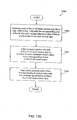
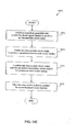
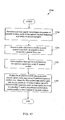
- FIG. 13B is a flow diagram of an example method 1350 of searching the N VQ codevectors stored in VQ codebook 1302 for a preferred one of the N VQ codevectors to be used in coding a speech or audio signal (method 1350 is also referred to as a prediction residual VQ codebook search of an NFC).
- Method 1350 is implemented using system 1300.
- predictor 1306 predicts a speech signal s(n) to derive a residual signal d(n).
- Predictor 1306 can include a predictor and a combiner, such as predictor 5002 and combiner 5004 discussed above in connection with FIG. 5, for example.
- input vector deriver 1308 derives N VQ input vectors u(n) each based on the residual signal d(n) and a corresponding one of the N VQ codevector stored in codebook 1302. Each of the VQ input vectors u(n) corresponds to one of N VQ error vectors q(n).
- Input vector deriver 1308 and step 1354 are described in further detail below.
- error energy calculator 1310 derives N VQ error energy values e(n) each corresponding to one of the N VQ error vectors q(n) associated with the N VQ input vectors u(n) of step 1354.
- Error energy calculator 1310 performs a squaring operation, for example, on each of the error vectors q(n) to derive the energy values corresponding to the error vectors.
- preferred codevector selector 1312 selects a preferred one of the N VQ codevectors as a VQ output vector uq(n) corresponding to the residual signal d(n), based on the N VQ error energy values e(n) derived by error energy calculator 1310.
- Predictor/filter restorer 1314 initializes and restores (that is, resets) the filter states and predictor states of various filters and predictors included in system 1300, during method 1350, as will be further described below.
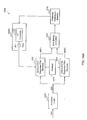
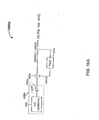
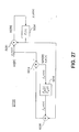
- FIG. 13C is a block diagram of a portion of an example codec structure or system 1362 used in a prediction residual VQ codebook search of TSNFC 5000 (discussed above in connection with FIG. 5).
- System 1362 includes scaled VQ codebook 5028a, and an input vector deriver 1308a (a specific embodiment of input vector deriver 1308) configured according to the embodiment of TSNFC 5000 of FIG 5.
- Input vector deriver 1308a includes essentially the same feedback structure involved in the quantizer codebook search as in FIG. 7, except the shorthand z -transform notations of filter blocks in FIG. 5 are used.
- Input vector deriver 1308a includes an outer or first stage NF loop including NF filter 5016, and an inner or second stage NF loop including NF filter 5038, as described above in connection with FIG. 5. Also, all of the filter blocks and adders (combiners) in input vector deriver 1308a operate sample-by-sample in the same manner as described in connection with FIG. 5.
- the method of operation of codec structure 1362 can be considered to encompass a single method.
- the method of operation of codec structure 1362 can be considered to include a first method associated with the inner NF loop of codec structure 1362 (mentioned above in connection with FIG. 13C), and a second method associated with the outer NF loop of the codec structure (also mentioned above).
- the first and second methods associated respectively with the inner and outer NF loops of codec structure 1362 operate concurrently, and in an inter-related manner (that is, together), with one another to form the single method.
- the aforementioned first and second methods that is, the inner and outer NF loop methods, respectively) are now described in sequence below.
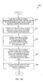
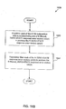
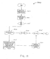
- FIG. 13D is an example first (inner NF loop) method 1364 implemented by system 1362 depicted in FIG. 13C.
- Method 1364 uses the inner NF loop of system 1362, as mentioned above.
- combiner 5036 combines each of the N VQ input vectors u(n) (mentioned above in connection with FIG. 13A) with the corresponding one of the N VQ codevectors from scaled VQ codebook 5028a to produce the N VQ error vectors q(n).
- filter 5038 separately filters at least a portion of each of the N VQ error vectors q(n) to produce N noise feedback vectors fq(n) each corresponding to one of the N VQ codevectors.
- Filter 5038 can perform either long-term or short-term filtering.
- Filter 5038 filters each of the error vectors q(n) on a sample-by-sample basis (that is, the samples of each error vector q(n) are filtered sequentially, sample-by-sample).
- Filter 5038 filters each of the N VQ error vectors q(n) based on an initial filter state of the filter corresponding to a previous preferred codevector (the previous preferred codevector corresponds to a previous residual signal).
- restorer 1314 restores filter 5038 to the initial filter state before the filter filters each of the N VQ codevectors.
- the initial filter state mentioned above is typically established as a result of processing many, that is, one or more, previous preferred codevectors.
- combining logic (5006, 5024, and 5026), separately combines each of the N noise feedback vectors fq(n) with the residual signal d(n) to produce the N VQ input vectors u(n).
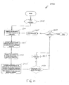
- FIG. 13E is an example second (outer NF loop) method 1370 executed concurrently and together with method 1364 by system 1362.
- Method 1370 uses the outer NF loop of system 1362, as mentioned above.
- combiner 5006 separately combines the residual signal d(n) with each of the N noise feedback vectors fqs(n) to produce N predictive quantizer input vectors v(n).
- predictor 5034 predicts each of the N predictive quantizer input vectors v(n) to produce N predictive, predictive quantizer input vectors pv(n).
- predictor 5034 predicts input vectors v(n) based on an initial predictor state of the predictor corresponding to (that is, established by) the previous preferred codevector. Therefore, restorer 1314 restores predictor 5034 to the initial predictor state before predictor 5034 predicts each of the N predictive quantizer input vectors v(n) in step 1374.
- combining logic e.g., combiners 5024, and 5026 separately combines each of the N predictive quantizer input vectors v(n) with a corresponding one of the N predicted, predictive quantizer input vectors pv(n) to produce the N VQ input vectors u(n).
- a combiner e.g. combiner 5030 combines each of the N predicted, predictive quantizer input vectors pv(n) with corresponding ones of the N VQ codevectors, to produce N predictive quantizer output vectors vq(n) corresponding to N VQ error vectors qs(n).
- filter 5016 separately filters each of the N VQ error vectors qs(n) to produce the N noise feedback vectors fqs(n).
- Filter 5016 can perform either long-term or short-term filtering.
- Filter 5016 filters each of the N VQ error vectors qs(n) on a sample-by-sample basis, and based on an initial filter state of the filter corresponding to at least the previous preferred codevector (see predicting step 1374 above). Therefore, restorer 1314 restores filter 5016 to the initial filter state before filter 5016 filters each of the N VQ codevectors in step 1380.
- VQ search systems and corresponding methods including embodiments based on codecs 3000, 4000, and 6000, for example, would be apparent to one of ordinary skill in designing speech codecs, based on the exemplary VQ search system and methods described above.
- a computationally more efficient codebook search method is based on the observation that the feedback structure in FIG. 13C, for example, can be regarded as a linear system with the VQ codevector out of scaled VQ codebook 5028a as its input signal, and the quantization error q(n) as its output signal.
- the output vector of such a linear system can be decomposed into two components: a ZERO-INPUT response vector qzi(n) and a ZERO-STATE response vector qzs(n).
- the ZERO-INPUT response vector qzi(n) is the output vector of the linear system when its input vector is set to zero.
- the ZERO-STATE response vector qzs(n) is the output vector of the linear system when its internal states (filter memories) are set to zero (but the input vector is not set to zero).
- FIG. 14A is a block diagram of an example NFC system 1400 for efficiently searching through N VQ codevectors, stored in the VQ codebook 1302 of scaled VQ codebook 5028a, for a preferred one of the N VQ codevectors to be used for coding a speech or audio signal.
- System 1400 includes scaled VQ codebook 5028a, a ZERO-INPUT response filter structure 1402, a ZERO-STATE response filter structure 1404, a restorer 1414 similar to restorer 1314 in FIG. 13A, an error energy calculator 1410 similar to error energy calculator 1310 in FIG. 13A, and a preferred codevector selector 1412 similar to preferred codevector selector 1312 in FIG. 13A.
- FIG. 14B is an example, computationally efficient, method 1430 of searching through N VQ codevectors for a preferred one of the N VQ codevectors, using system 1400.
- predictor 1306 predicts speech signal s(n) to derive a residual signal d(n).
- ZERO-INPUT response filter structure 1402 derives ZERO-INPUT response error vector qzi(n) common to each of the N VQ codevectors stored in VQ codebook 1302.
- ZERO-STATE response filter structure 1404 derives N ZERO-STATE response error vectors qzs(n) each based on a corresponding one of the N VQ codevectors stored in VQ codebook 1302.
- error energy calculator 1410 derives N VQ error energy values each based on the ZERO-INPUT response error vector qzi(n) and a corresponding one of the N ZERO-STATE response error vectors qzs(n).
- Preferred codevector selector 1412 selects the preferred one of the N VQ codevectors based on the N VQ error energy values derived by error energy calculator 1410.
- the qzi(n) vector derived at step 1434 captures the effects due to (1) initial filter memories in ZERO-INPUT response filter structure 1402, and (2) the signal vector of d(n). Since the initial filter memories and the signal d(n) are both independent of the particular VQ codevector tried, there is only one ZERO-INPUT response vector, and it only needs to be calculated once for each input speech vector.
- the initial filter memories and d(n) are set to zero.
- N ZERO-STATE response vectors qzs(n) For each VQ codebook vector tried, there is a corresponding ZERO-STATE response vector qzs(n). Therefore, for a codebook of N codevectors, we need to calculate N ZERO-STATE response vectors qzs(n) for each input speech vector, in one embodiment of the present invention.
- N ZERO-STATE response vectors qzs(n) for a group of input speech vectors, instead of for each of the input speech vectors, as is further described below.
- FIG. 14C is a block diagram of an example ZERO-INPUT response filter structure 1402a (a specific embodiment of filter structure 1402) used during the calculation of the ZERO-INPUT response of q(n) of FIG. 13C.
- ZERO-INPUT response filter structure 1402a includes filter 5038 associated with an inner NF loop of the filter structure, and filter 5016 associated with an outer NF loop of the filter structure.
- the method of operation of codec structure 1402a can be considered to encompass a single method.
- the method of operation of codec structure 1402a can be considered to include a first method associated with the inner NF loop of codec structure 1402a, and a second method associated with the outer NF loop of the codec structure.
- the first and second methods associated respectively with the inner and outer NF loops of codec structure 1402a operate concurrently, and together, with one another to form the single method.
- the aforementioned first and second methods that is, the inner and outer NF loop methods, respectively) are now described in sequence below.
- FIG. 14D is an example first (inner NF loop) method 1450 of deriving a ZERO-INPUT response using ZERO-INPUT response filter structure 1402a of FIG. 14C.
- Method 1450 includes operation of the inner NF loop of system 1402a.
- an intermediate vector vzi(n) is derived based on the residual signal d(n).
- the intermediate vector vzi(n) is predicted (using predictor 5034, for example) to produce a predicted intermediate vector vqzi(n).
- Intermediate vector vzi(n) is predicted based on an initial predictor state (of predictor 5034, for example) corresponding to a previous preferred codevector.
- the initial predictor state mentioned above is typically established as a result of a history of many, that is, one or more, previous preferred codevectors.
- the intermediate vector vzi(n) and the predicted intermediate vector vqzi(n) are combined with a noise feedback vector fqzi(n) (using combiners 5026 and 5024, for example) to produce the ZERO-INPUT response error vector qzi(n).
- a next step 1458 the ZERO-INPUT response error vector qzi(n) is filtered (using filter 5038, for example) to produce the noise feedback vector fqzi(n).
- Error vector qzi(n) can be either long-term or short-term filtered.
- error vector qzi(n) is filtered based on an initial filter state (of filter 5038, for example) corresponding to the previous preferred codevector (see predicting step 1454 above).
- FIG. 14E is an example second (outer NF loop) method 1470 of deriving a ZERO-INPUT response, executed concurrently with method 1450, using ZERO-INPUT response filter structure 1402a.
- Method 1470 includes operation of the outer NF loop of system 1402a.
- Method 1470 shares some method steps with method 1450, described above.
- a first step 1472 the residual signal d(n) is combined with a noise feedback signal fqszi(n) (using combiner 5006, for example) to produce an intermediate vector vzi(n).
- the intermediate vector vzi(n) is predicted to produce a predicted intermediate vector vqzi(n).
- the intermediate vector vzi(n) is combined with the predicted intermediate vector vqzi(n) (using combiner 5014, for example) to produce an error vector qszi(n).
- error vector qszi(n) is filtered (using filter 5016, for example) to produce the noise feedback vector fqszi(n).
- Error vector qszi(n) can be either long-term or short-term filtered.
- error vector qszi(n) is filtered based on an initial filter state (of filter 5038, for example) corresponding to the previous preferred codevector (see predicting step 1454 above).
- FIG. 15A is a block diagram of an example ZERO-STATE response filter structure 1404a (a specific embodiment of filter structure 1404) used during the calculation of the ZERO-STATE response of q(n) in FIG. 13C.
- the two long-term filters 5038 and 5034 in FIG. 13A have no effect on the calculation of the ZERO-STATE response vector. Therefore, they can be omitted.
- the resulting structure during ZERO-STATE response calculation is depicted in FIG. 15A.
- FIG. 15B is a flowchart of an example method 1520 of deriving a ZERO-STATE response using filter structure 1404a depicted in FIG. 15A.
- a first step 1522 an error vector qszs(n) associated with each of the N VQ codevectors stored in scaled VQ codebook 5028a is filtered (using filter 5016, for example) to produce a ZERO-STATE input vector vzs(n) corresponding to' each of the N VQ codevectors.
- Each of the error vectors qszs(n) is filtered based on an initially zeroed filter state (of filter 5016, for example). Therefore, the filter state is zeroed (using restorer 1414, for example) to produce the initially zeroed filter state before each error vector qszs(n) is filtered.
- each ZERO-STATE input vector vzs(n) produced in filtering step 1522 is separately combined with the corresponding one of the N VQ codevectors (using combiner 5036, for example), to produce the N ZERO-STATE response error vectors qzs(n).
- FIG. 15A is a block diagram of filter structure 1404b according to a simplified embodiment of ZERO-STATE response filter structure 1404. Filter structure 1404b is equivalent to filter structure 1404a of FIG. 15A.
- FIG. 16B is a flowchart of an example method 1620 of deriving a ZERO-STATE response using filter structure 1404b of FIG. 16A.
- a first step 1622 each of N VQ codevectors is combined with a corresponding one of N filtered, ZERO-STATE response error vectors vzs(n) to produce the N ZERO-STATE response error vectors qzs(n).
- each of the N ZERO-STATE response error vectors qzs(n) is separately filtered to produce the N filtered, ZERO-STATE response error vectors vzs(n).
- Each of the error vectors qzs(n) is filtered based on an initially zeroed filter state. Therefore, the filter state is zeroed to produce the initially zeroed filter state before each error vector qzs(n) is filtered.
- the following enumerated steps represent an example of processing one VQ codevector CV(n) including four samples CV(n) 0..3 sample-by-sample according to steps 1622 and 1624 using filter structure 1404b, to produce a corresponding ZERO-STATE error vector qzs(n) including four samples qzs(n) 0..3 :
- Using a sign-shape structured VQ codebook can further reduce the codebook search complexity.
- a sign bit plus a ( B - 1)-bit shape codebook with 2 B -1 independent codevectors For each codevector in the ( B - 1)-bit shape codebook, the negated version of it, or its mirror image with respect to the origin, is also a legitimate codevector in the equivalent B -bit sign-shape structured codebook.
- the overall bit rate is the same, and the codec performance should be similar.
- the side information encoding rates are 14 bits/frame for LSPI , 7 bits/frame for PPI , 5 bits/frame for PPTI , and 4 bits/frame for GI . That gives a total of 30 bits/frame for all side information.
- the encoding rate is 80 bits/frame, or 16 kb/s.
- Such a 16 kb/s codec with a 5 ms frame size and no look ahead gives output speech quality comparable to that of G.728 and G.729E.
- the speech signal used in the vector quantization embodiments described above can comprise a sequence of speech vectors each including a plurality of speech samples.
- the various filters and predictors in the codec of the present invention respectively filter and predict various signals to encode speech signal s(n) based on filter and predictor (or prediction) parameters (also referred to in the art as filter and predictor taps, respectively).
- the codec of the present invention includes logic to periodically derive, that is, update, the filter and predictor parameters, and also the gain g(n) used to scale the VQ codebook entries, based on the speech signal, once every M speech vectors, where M is greater than one. Codec embodiments for periodically deriving filter, prediction, and gain scaling parameters were described above in connection with FIG. 7.
- the present invention takes advantage of such periodic updating of the aforementioned parameters to further reduce the computational complexity associated with calculating the N ZERO-STATE response error vectors qzs(n), described above.
- the N ZERO-STATE response error vectors qzs(n) derived using filter structure 1404b depend on only the N VQ codevectors, the gain value g(n), and the filter parameters (taps) applied to filter 5034.
- the N ZERO-STATE response error vectors qzs(n) corresponding to the N VQ codevectors are correspondingly constant over the M speech vectors. Therefore, the N ZERO-STATE response error vectors qzs(n) need only be derived when the gain g(n) and/or filter parameters for filter 5034 are updated once every M speech vectors, thereby reducing the overall computational complexity associated with searching the VQ codebook for a preferred one of the VQ codevectors.
- FIG. 17 is a flowchart of an example method 1700 of further reducing the computational complexity associated with searching the VQ codebook for a preferred one of the VQ codevectors, in accordance with the above description.
- a speech signal is received.
- the speech signal comprises a sequence of speech vectors, each of the speech vectors including a plurality of speech samples.
- a gain value is derived based on the speech signal once every M speech vectors, where M is an integer greater than 1.
- filter parameters are derived/updated based on the speech signal once every T speech vectors, where T is an integer greater than one, and where T may, but does not necessarily, equal M.
- the N ZERO-STATE response error vectors qzs(n) are derived once every T and/or M speech vectors (i.e., when the filter parameters and/or gain values are updated, respectively), whereby a same set of N ZERO-STATE response error vectors qzs(n) is used in selecting a plurality of preferred codevectors corresponding to a plurality of speech vectors.
- VQ search systems and corresponding methods including embodiments based on codecs 3000, 4000, and 6000, for example, would be apparent to one of ordinary skill in designing speech codecs, based on the exemplary VQ search system and methods described above.
- the present invention provides first and second additional efficient VQ search methods, which can be used independently or jointly.
- the first method (described below in Section IX.C.1.) provides an efficient VQ search method for a general VQ codebook, that is, no particular structure of the VQ codebook is assumed.
- the second method (described below in Section IX.C.2.) provides an efficient method for the excitation quantization in the case where a signed VQ codebook is used for the excitation.
- the first method reduces the complexity of the excitation VQ in NFC by reorganizing the calculation of the energy of the error vector for each candidate excitation vector, also referred to as a codebook vector.
- the energy of the error vector is the cost function that is minimized during the search of the excitation codebook.
- the reorganization is obtained by:
- the second method represents an efficient way of searching the excitation codebook in the case where a signed codebook is used.
- the second method is obtained by reorganizing the calculation of the energy of the error vector in such a way that only half of the total number of codevectors is searched.
- first and second methods also provides an efficient search.
- first and second methods are used separately. For example, if a signed codebook is not used, then the second invention does not apply, but the first invention may be applicable.
- quantization energy e(n) refers to a quantization energy derivable from an error vector q(n), where n is a time/sample position descriptor. Quantization energy e(n) and error vector q(n) are both associated with a VQ codevector in a VQ codebook.
- the ZERO-INPUT response error vector is denoted qzi(n), where n is the time index.
- the ZERO-INPUT response error vector is denoted q zi (k), where k refers to the k th sample of the ZERO-INPUT response error vector.
- the ZERO-STATE response error vector is denoted qzs(n), where n is the time index.
- the ZERO-STATE response error vector is denoted q zs,n (k), where n denotes the n th VQ codevector of the N VQ codevectors, and k refers to the k th sample of the ZERO-STATE response error vector.
- Section IX.B. above refers to "frames,” for example 5 ms frames, each corresponding to a plurality of speech vectors. Also, multiple bits of side information and VQ codevector indices are transmitted by the coder in each of the frames.
- subframe is taken to be synonymous with “frame” as used in the Sections above.
- sub-vectors refers to vectors within a subframe.
- the energy, E n , of the error vector, q n ( k ), of the n th codevector is given by and the optimal codevector, n opt , is given by the codevector, n , that minimizes E n , i.e. where N is the number of codevectors.
- K M K M K
- L K M K
- the ZERO-STATE responses of the codevectors are unchanged for the L VQs and need only be calculated once (in the case where the gain and/or filter parameters are updated once every L VQs).
- Table 1 summarized in Table 1 below in comparison with the equivalent numbers for the present invention.
- Eq. 7 the energy of the error vector is expanded into the energy of the ZERO-INPUT response, Eq. 8, the energy of the ZERO-STATE response, Eq. 9, and two times the cross-correlation between the ZERO-INPUT response and the ZERO-STATE response, Eq. 10.
- the minimization of the energy of the error vector as a function of the codevector is independent of the energy of the ZERO-INPUT response since the ZERO-INPUT response is independent of the codevector. Consequently, the energy of the ZERO-INPUT response can be omitted when searching the excitation codebook. Furthermore, since the N energies of the ZERO-STATE responses of the codevectors are unchanged for the L VQs, the N energies need only be calculated once.
- VQ operation can be expressed as:
- a second invention devises a way to reduce complexity in the case a signed codebook is used for the excitation VQ.
- the sign is represented by 1 bit
- the linear independent codevectors by B - 1 bits.
- the present second invention further reduces the complexity of searching a signed codebook by manipulating the minimization operation.
- the term of the energy of the error vector is expanded, except for the further incorporation of the property of a signed codebook.
- s is the sign and n ⁇ 1,..., N /2 ⁇ represents the N /2 linear independent codevectors.
- the energy of the error vector is examined for a pair of codevectors in the signed codebook. According to Eq. 16 the energy of the error vector can be expanded into the energy of the ZERO-INPUT response, Eq. 8, the energy of the ZERO-STATE response, Eq. 9, and two times the cross-correlation between the ZERO-INPUT response and the ZERO-STATE response, Eq. 10.
- the sign of the cross-correlation term depends on the sign of the codevector.
- the minimization of the energy of the error vector as a function of the codevector is independent of the energy of the ZERO-INPUT response since the ZERO-INPUT response is independent of the codevector. Consequently, the energy of the ZERO-INPUT response can be omitted when searching the excitation codebook, and the search is given by
- the search can be specified as where the less-than sign is interchangeable with a less-than-or-equal sign.
- the number of floating point operations needed to calculate the energy of the error vector for all of the combined N codevectors for all of the L VQs according to the search specified by Eq. 20 is Again, disregarding the calculation of the ZERO-INPUT and ZERO-STATE responses.
- the example numbers are summarized in Table 1.
- This method would also apply to a signed sub-codebook within a codebook, i.e. a subset of the code vectors of the codebook make up a signed codebook. It is then possible to apply the invention to the signed sub-codebook.
- the number of VQs per master vector, L is greater than one, and a signed codebook (or sub-codebook) is used it is advantageous to combine the two methods above.
- the example numbers are summarized in Table 1.
- the methods of the present invention are used in an NFC system to quantize a prediction residual signal. More generally, the methods are used in an NFC system to quantize a residual signal. That is, the residual signal is not limited to a prediction residual signal, and thus, the residual signal may include a signal other than a prediction residual signal.
- the prediction residual signal (and more generally, the residual signal) includes a series of successive residual signal vectors. Each residual signal vector needs to be quantized. Therefore, the methods of the present invention search for and select a preferred one of a plurality of candidate codevectors corresponding to each residual vector. Each preferred codevector represents the excitation VQ of the corresponding residual signal vector.
- FIG. 18 is a flow chart of an example method 1800 of quantizing multiple vectors, for example, residual signal vectors, in a master vector (or frame), according to the correlation techniques described in Sections IX.C.1 and IX.C.2.
- Method 1800 is implemented in an NFC system.
- method 1800 is useable with the exemplary NFC systems, structures, and methods described in connection with FIGs. 1-17, to the extent excitation VQ is used in these systems, structures, and methods.
- Each of these NFC systems includes at least one noise feedback loop/filter to shape coding noise.
- method 1800 uses an unsigned or general VQ codebook including N unsigned candidate codevectors (see Section IX.C.1.b. above).
- method 1800 uses a signed VQ codebook including N signed candidate codevectors (see Section IX.C.2.b above).
- the signed VQ codebook represents a product of:
- Method 1800 assumes there are L vectors in the master vector (or frame) and that the ZERO-STATE responses of the N codevectors (which may be signed or unsigned, as mentioned above) are invariant over the L vectors, because gain and/or filter parameters in the NFC system are updated only once every L vectors.
- N ZERO-STATE responses are calculated.
- the N ZERO-STATE responses may be calculated using the NFC filter structures of FIGs. 15A and 16A, and associated methods, for example.
- N ZERO-STATE energies corresponding to the N ZERO-STATE responses of step 1805, are calculated.
- an initial one of the L vectors in the frame to be quantized is identified.
- a loop including steps 1820, 1825, 1830, 1835 and 1840 is repeated for each of the vectors to be quantized in the frame.
- Each iteration of the loop produces an excitation VQ corresponding to a successive one of the vectors in the frame, beginning with the initial vector.
- a ZERO-INPUT response corresponding to the given (that is, identified) vector is calculated.
- a ZERO-INPUT response corresponding to the first vector in the frame is calculated.
- the ZERO-INPUT response may be calculated using the NFC filter structure described above in connection with FIG. 14C, and methods associated therewith, for example.
- a best or preferred codevector is selected from among the N codevectors based on minimization terms.
- the minimization terms are derived based on the N ZERO-STATE energies from step 1810, and cross-correlations between the ZERO-INPUT response from step 1820 and ZERO-STATE responses from step 1805.
- step 1825 is governed by Eq. 11 of Section IX.C.1.b. above.
- step 1825 is governed by Eq. 20 of Section IX.C.2.b. above. Step 1825 is described further below in connection with FIGs. 19 and 20.
- filter memories in the NFC system used to implement method 1800 are updated using the best or preferred codevector selected in step 1825.
- a decision step 1835 it is determined whether a last one of the vectors in the frame has been quantized. If yes, then the method is done. On the other hand, if further vectors in the frame remain to be quantized, flow proceeds to a step 1840, and a next one of the vectors to be quantized in the frame is identified. The quantization loop repeats for the next vector, and so on, for each of the L vectors in the frame.
- FIG. 19 is a flowchart of an example method 1900 expanding on step 1825 of FIG. 18, using a general, or unsigned VQ codebook.
- method 1900 corresponds to a VQ search of an unsigned VQ codebook, as described in Section IX.C.1.b., above.
- Method 1900 represents a search of the N candidate codevectors in the codebook to select the preferred codevector to be used as the excitation quantization in step 1825.
- a first step 1905 a first one of the N codevectors to be examined/tested is identified.
- a search loop including steps 1910 through 1945, is repeated for each of the N codevectors, beginning with the first codevector identified in step 1905.
- one of the ZERO-STATE responses calculated in step 1805 is retrieved.
- the retrieved ZERO-STATE response corresponds to the codevector being tested during the current iteration of the search loop. For example, the first time through the loop, the ZERO-STATE response corresponding to the first codevector is retrieved.
- a cross-correlation between the ZERO-STATE response and the ZERO-INPUT response is calculated.
- the cross-correlation produces a correlation term (also referred to as a "correlation result").
- step 1920 the ZERO-STATE energy, corresponding to the ZERO-STATE response of step 1910, is retrieved.
- a minimization term corresponding to the codevector being tested in the current iteration of the search loop.
- the minimization term is based on the retrieved ZERO-STATE energy, and a cross-correlation between the ZERO-STATE response of the codevector being tested and the ZERO-INPUT response.
- the ZERO-STATE energy and the cross-correlation term are combined (for example, the ZERO-STATE energy and cross-correlation term are added as in Eq. 11, and as in Eq. 20 when the cross-correlation term is negative).
- the current minimization term (just calculated in step 1925) is compared to the minimization terms resulting from previous iterations through the search loop, to identify a current best minimization term from among all of the minimization terms calculated thus far.
- the codevector corresponding to this current best minimization term is also identified.
- a next step 1940 it is determined whether a last one of the N codevectors has been tested. If yes, then the method is done because the codebook has been searched, and a preferred codevector has been determined. However, if no, at step 1945, then a next one of the N codevectors to be tested is identified, and the search loop is repeated.
- method 1900 performs the following steps:
- the prediction residual signal (more generally, the residual signal) includes a series of prediction residual vectors (more generally, a series of residual vectors), and method 1900 is repeated for each of the residual vectors in accordance with method 1800, overall the method produces an excitation quantization corresponding to each of the prediction residual vectors (and more generally, to each of the residual vectors).
- a first shape codevector to be tested (for example, codevector c 1 ) in the shape codebook is identified.
- the ZERO-STATE response of the shape codevector is retrieved.
- step 2015 the energy of the ZERO-STATE response of step 2010 is retrieved.
- a cross-correlation term between the ZERO-STATE response of the shape codevector and the ZERO-INPUT response is calculated.
- the sign of the cross-correlation term may be a first value (for example, negative) or a second value (for example, positive).
- the sign value of the cross-correlation term is determined. For example, it is determined whether the cross-correlation term is positive. If yes (the cross-correlation term is positive), then at step 2030, a minimization term is calculated as the energy of the ZERO-STATE response minus the cross-correlation term. In block 2030, the phrase "sign is negative" indicates block 2030 corresponds to the negative codevector. Thus, arriving at block 2030 indicates the negative codevector is the preferred one of the negative and positive codevectors corresponding to the current shape codevector (see Eq. 20 of Section IX.C.2.b. above).
- the minimization term is calculated as the energy of the ZERO-STATE response plus the cross-correlation term.
- the phrase "sign is positive" indicates block 2035 corresponds to the positive codevector.
- arriving at block 2035 indicates the positive codevector is the preferred one of the negative and positive codevectors corresponding to the current shape codevector.
- steps 2040 and 2045 determine the best current minimization term among all of the minimization terms calculated so far, and also, identify the signed codevector associated with the best current minimization term.
- a next step 2050 it is determined whether the last codevector in the shape codebook has been tested. If yes, then the search is completed and the preferred shape codevector and its sign have been determined. If no, then at step 2055, the next shape codevector to be tested in the shape codebook is identified.
- method 2000 performs the following steps for each vector to be quantized:
- Example methods 1900 and 2000 each derive a minimization term corresponding to a codevector in each iteration of their respective search loops.
- all of the minimization terms may be calculated in a single step, followed by a single step search through all of these minimization terms to select the preferred minimization term, and corresponding codevector.
- This section provides a summary and comparison of the number of floating point operations that is required to perform the L VQs in a master vector for the different methods.
- the comparison assumes that the same techniques are used to obtain the ZERO-INPUT response and ZERO-STATE responses for the different methods, and thus, that the complexity associated herewith is identical for the different methods. Consequently, this complexity is omitted from the estimated number of floating point operations.
- the different methods are mathematically equivalent. i.e., all are equivalent to an exhaustive search of the codevectors.
- Table 1 lists the expression for the number of floating point operations as well as the number of floating point operations for the example narrowband and wideband NFC systems.
- This Section presents efficient methods related to excitation quantization in noise feedback coding where the short-term shaping of the coding noise is generalized. The methods are based in part on separating an NFC quantization error signal into ZERO-STATE and ZERO-INPUT response contributions. Additional new parts are developed and presented in order to accommodate a more general shaping of the coding noise while providing efficient excitation quantization. This includes an efficient method of calculating the ZERO-STATE response with the generalized noise shaping, and an efficient method for updating the filter memories of the noise feedback coding structure with the generalized noise shaping, as will be described below. Although the methods of this section are describe by way of example in connection with NFC system/coder 6000 of FIG. 6, they may be applied more generally to any NFC systems, or other coding systems.
- the NFC systems depicted in FIGs. 21-28 operate generally in a manner similar to that described in connection with previous Sections, and apparent to one of ordinary skill in the relevant art(s) after having read the present description. Thus, the operation of the NFC systems depicted in FIGs. 21-28 will not be described herein in detail.
- FIG. 21 is a diagram of an example NFC system/coder 2100 used for excitation quantization (for example, a VQ search) in NFC 6000 of FIG. 6.
- NFC system 2100 represents, and is also referred to herein as an NF filter structure 2100.
- NFC system 2100 includes short-term predictor/prediction, P s ( z ) (6012), long-term predictor/prediction, P l ( z ) (5034), short-term noise shaping filter, N s ( z ) (representing a portion of noise feedback filter 6016), and long-term noise shaping filter, N l ( z ) (representing a portion of noise feedback filter 5038).
- Filter labels include the subscripts " s " and " l “ to indicate “short-term” and "long-term,” respectively.
- This Section includes a slight change in the filter (and filter response) naming convention used in previous Sections. Namely, the " s " and “ l “ indicators were not subscripted in the FIGs. discussed in connection with previous Sections herein, but are subscripted in FIGs. 21-28 for consistency with the ensuing description directed to these FIGs.
- filters P s ( z ), P l ( z ), N s ( z ) and N l ( z ) correspond to filters Ps ( z ), Pl ( z ), Ns ( z ) and Nl ( z ) described in previous Sections.
- the short-term noise feedback filter, F s ( z ) N s ( z )- 1 (where F s (z) is the response of filter 6016), will shape the coding noise, i.e. quantization error, according to the filter response of N s ( z ). This provides for a flexible control of the coding noise, where masking effects of the human auditory system can be exploited.
- the short-term noise shaping filter, N s ( z ), can be effectively controlled by linking the pole- and zero- sections to the spectral envelope of the input signal by means of a short-term Linear Predictor Coefficient (LPC) analysis.
- LPC Linear Predictor Coefficient
- the short-term noise shaping filter of Eq. 28 takes the form (that is, has a filter response) where the zero- and pole-sections are given by and respectively.
- FIG. 22 is an example NFC system 2200 including such a short-term noise feedback filter (6016).
- the only difference between FIG. 21 and FIG. 22 is the different form of the filter response indicated inside the box corresponding to noise feedback filter 6016.
- the efficient excitation quantization method described in this Section includes four steps:
- NFC system 2100 of FIG. 21 (and system 2200 of FIG. 22) is operable in a ZERO-STATE configuration and a ZERO-INPUT configuration.
- the ZERO-STATE configuration is obtained/derived by zeroing the contents of the memories of the filters in NFC system 2100.
- the ZERO-INPUT configuration is obtained by applying a null or zero VQ codevector to NFC system 2100.
- FIG. 23 is an example ZERO-STATE configuration 2300 corresponding to NFC system 2100.
- This ZERO-STATE configuration is also equivalently referred to as a ZERO-STATE response filter structure 2300 and a ZERO-STATE filter structure 2300.
- ZERO-STATE filter structure 2300 is used to calculate the ZERO-STATE response, q zs ( n ), of NFC system 2100, for each of N VQ codevectors.
- the N VQ codevectors could be stored in a VQ codebook, or they could be a function of multiple contributions, e.g. a product code such as the sign-shape code/signed codebook of section IX.C.
- ZERO-STATE filter structure 2400 depicted in FIG. 24.
- ZERO-STATE filter structure 2300 can be reduced to the equivalent and less complex filter structure 2400, where where is the prediction error filter of the quantized LPC, and N is the order of the quantized LPC, which could be different from the order of the LPC for the short-term noise shaping filter, N NFF .
- Using a ZERO-STATE filter structure (such as structure 2300 or 2400) to calculate a ZERO-STATE response corresponds to operating the NFC system (for example, NFC system 6000/2100) in the ZERO-STATE condition.
- NF system 6000/2100 is operable in the ZERO-STATE condition.
- the filter memories of the various filters of the ZERO-STATE filter structure 2300 are initialized to zero before calculation of the ZERO-STATE response of each VQ codevector , per definition, and the filter operation given by the ZERO-STATE filter structure 2300 can advantageously be transformed to an equivalent low order all-zero filter operation.
- Filter structure 2400 has a substantially equivalent filter response to that of filter structure of FIG. 23.
- the first K coefficients of the impulse response of the all-zero IIR filter are obtained by passing an impulse through the pole-zero filter given by Eq. 32 exploiting that all filter memories are initialized to zero. This is equivalent to filtering the impulse response of the zero section of H ( z ) in Eq. 32, through the remaining all-pole part: exploiting that only the first K samples of the output are needed. These first K samples of the output are the first K coefficients of the impulse response of the all-zero IIR filter.
- the gain-scaling step in FIG. 24, represented within block 5028a in FIG. 24, can advantageously be integrated into the all-zero filter by multiplying the all-zero filter coefficients with the gain.
- the gain-scaling represented in block 5028a can be moved to the all-zero filter, wherein a modified block 5028a produces non-scaled VQ codevectors, and the all-zero filter performs the gain-scaling instead.
- the ZERO-STATE responses of the VQ codevectors can then efficiently be obtained by passing the non-scaled VQ codevectors, simply the VQ codevectors, through the all-zero filter with the modified coefficients. Referring to FIG. 24 and Eq.
- both methods are referred as filtering a VQ codevector with the all-zero filter to obtain the ZERO-STATE reponse corresponding to the VQ codevector.
- the gain-scaling in FIGs 21-24 can be integrated into the VQ codebook by multiplying all VQ codevectors with the gain prior to the excitation quantization hereby producing a modified VQ codebook.
- the VQ codevectors of the modified VQ codebook would directly represent candidate excitation vectors and would in fact be gain-scaled VQ codevectors.
- VQ codevectors covers both non-scaled and gain-scaled VQ codevectors.
- FIG. 25 is an example ZERO-INPUT filter configuration or structure 2500 corresponding to NFC structure 2200.
- the filter structure of FIG. 25 is used to calculate the ZERO-INPUT response, q zi ( n ), for the NFC system of FIG. 22. Calculating the ZERO-INPUT response, q zi ( n ), using the filter structure of FIG. 25 corresponds to operating NFC system 2100 in the ZERO-INPUT condition.
- the VQ codevector that minimizes is selected and the quantized excitation vector is denoted u q ( n ).
- the term "memory update” refers to a signal that is shifted into, or feeds, a filter memory of a filter included in a filter structure. Consequently, past values of this signal are stored in the filter memory.
- the memory update signals feeding the various filters are indicated using duplicate labels, for purposes of descriptive convenience and clarity. That is, in FIGs. 26-28, each of these signals has a first label that is the same as the label used to identify the corresponding signal in the systems/structures of FIGs. 21-25, and a second label indicating the filter being fed by that signal. The second label is useful in describing the transformation of the filter structure of FIG.
- FIG. 26 An example basic structure to update the filter memories for the NFC system of FIG. 22 is depicted in FIG. 26. This includes
- An alternative and more efficient method is to calculate the five filter memory updates as the superposition of the contributions to the filter memories from the ZERO-STATE and the ZERO-INPUT configurations (also referred to as ZERO-STATE and ZERO-INPUT components).
- the contributions from the ZERO-STATE component/configuration to the five filter memories are denoted p s zs ( n ), p l zs ( n ), n l zs ( n ), f sz zs ( n ), and f sp zs ( n ), respectively, and the contributions from the ZERO-INPUT component/configuration are denoted p s zi ( n ), p l zi ( n ), n l zi ( n ), f sz zi ( n ), and f sp zi ( n ), respectively.
- FIG. 28 The structure to calculate the contributions to the five filter memories from the ZERO-INPUT component/configuration is depicted in FIG. 28. (Note that FIGs. 25 and 28 are the same, except duplicate signal labels are added in FIG. 28) However, referring to FIG. 25, it is evident that the ZERO-INPUT contributions to the five filter memories are all available from the previous calculation of the ZERO-INPUT response, q zi ( n ), prior to the codebook search, and consequently, no additional calculations are necessary.
- the excitation quantization of each input vector, of dimension K results in K new values being shifted into each filter memory during the filter memory update process.
- FIG. 29 is a flow chart of an example method 2900 of selecting a best VQ codevector representing the quantized excitation vector corresponding to an input vector, using a zero-state calculation as described in this Section.
- This corresponds to performing a VQ search of an NFC system, such as the NFC system of FIG. 21.
- the NFC system includes a NF filter in a NF path or loop of the NFC system.
- the NFC system is operable in a ZERO-STATE configuration, including the ZERO-STATE filter structure of FIG. 23, for example.
- the NFC system is operable in a ZERO-INPUT configuration, including the ZERO-INPUT filter structure of FIG. 25, for example.
- the various steps of method 2900, described below, are performed in accordance with the equations of this Section.
- a first step 2902 includes producing a ZERO-INPUT response error vector common to each of N candidate VQ codevectors.
- the ZERO-INPUT filter structure/NFC configuration of FIG. 25 can be used to calculate the ZERO-INPUT response error vector (e.g., error vector qzi(n)).
- a next step 2904 includes separately filtering each of the N VQ codevectors with an all-zero filter (e.g., filter 2404) having a filter response that is substantially equivalent to a filter response of the ZERO-STATE filter structure, to produce N ZERO-STATE response error vectors (e.g., N error vectors qzs(n)).
- an all-zero filter e.g., filter 2404
- N ZERO-STATE response error vectors e.g., N error vectors qzs(n)
- a next step 2906 includes selecting a preferred one of the N VQ codevectors representing the quantized excitation vector corresponding to the input signal vector based on the ZERO-INPUT response error vector and the N ZERO-STATE response error vectors. This step may be performed in accordance with Eq. 40, and uses efficient correlation techniques similar to those described above in Sections IX.C.2.-IX.C.5.
- Method 2900 may also include a filter transformation step before step 2904.
- the filter transformation step includes transforming the ZERO-STATE filter structure (e.g., of FIG. 23) to a filter structure (e.g. of FIG. 24) including only the all-zero filter (e.g., filter 2404).
- FIG. 30 is a flow chart of an example method 3000 of efficiently performing a ZERO-STATE calculation in an NFC system having a corresponding initial or first ZERO-STATE filter structure (e.g., the structure of FIG. 23), where the ZERO-STATE filter structure includes multiple filters (e.g., filters 6016 and 6012).
- Method 3000 efficiently produces a ZERO-STATE response error vector for the NFC system, useable in other methods related to excitation quantization, for example.
- a first step 3002 includes transforming the first ZERO-STATE filter structure (e.g., of FIG. 23) having multiple filters to a second, simpler ZERO-STATE filter structure (e.g., of FIG. 24) including only a single filter, for example, an all-zero filter (e.g., filter 2404).
- the all-zero filter has a filter response substantially equivalent to a filter response of the first ZERO-STATE filter structure.
- a next step 3004 includes filtering a VQ codevector with the all-zero filter to produce a ZERO-STATE response error vector corresponding to the VQ codevector.
- the VQ codevector is one of N VQ codevectors
- method 3000 further includes filtering the remaining N-1 VQ codevectors with the all-zero filter to produce N ZERO-STATE response error vectors corresponding to the N VQ codevectors.
- FIG. 31 is a flow chart of an example method 3100 for updating one or more filter memories in an NFC system, such as the NFC system of FIG. 2100.
- the NFC system is operable in a ZERO-STATE condition (wherein the NFC system is in a ZERO-STATE configuration) and a ZERO-INPUT condition (wherein the NFC is in a ZERO-INPUT configuration), and includes at least one filter (e.g., filter 6016) having a filter memory.
- the various steps of method 3000 described below, may be performed in accordance with the equations of this Section.
- a first step 3102 includes producing a ZERO-STATE contribution (e.g., f sz zs(n) ) to the filter memory, when the NFC system is in the ZERO-STATE condition.
- a ZERO-STATE contribution e.g., f sz zs(n)
- the structure of FIG. 27 may be used to produce the ZERO-STATE contribution.
- "Producing” may include calculating, or alternatively, retrieving/accessing previously calculated values.
- a next step 3104 includes producing a ZERO-INPUT contribution (e.g., f sz zi(n) ) to the filter memory, when the NFC system is in the ZERO-INPUT condition.
- a ZERO-INPUT contribution e.g., f sz zi(n)
- the structure of FIG. 28 may be used to calculate the ZERO-INPUT contribution.
- the order of steps 3102 and 3104 is reversed. That is, step 3104 precedes step 3102.
- a next step includes updating the filter memory as a function of both the ZERO-STATE contribution and the ZERO-INPUT contribution.
- Method 3100 is typically, though not necessarily, performed in the context of excitation quantization, that is, a VQ search.
- method 3100 includes, prior to step 3102, a step of searching N VQ codevectors associated with the NFC system for a best VQ codevector representing a quantized excitation vector. Then, step 3102 comprises producing the ZERO-STATE contribution, as mentioned above, corresponding to the best VQ codevector.
- the decoder in FIG. 8 is very similar to the decoder of other predictive codecs such as CELP and MPLPC.
- the operations of the decoder are well-known prior art.
- the bit de-multiplexer block 100 unpacks the input bit stream into the five sets of indices LSPI , PPI , PPTI , GI , and CI .
- the decoded pitch period and pitch predictor taps are passed to the long-term predictor block 140.
- the short-term predictive parameter decoder block 120 decodes LSPI to get the quantized version of the vector of LSP inter-frame MA prediction residual. Then, it performs the same operations as in the right half of the structure in FIG. 10 to reconstruct the quantized LSP vector, as is well known in the art. Next, it performs the same operations as in blocks 17 and 18 to get the set of short-term predictor coefficients ⁇ ⁇ , which is passed to the short-term predictor block 160.
- the prediction residual quantizer decoder block 130 decodes the gain index GI to get the quantized version of the log-gain prediction residual. Then, it performs the same-operations as in blocks 304, 307, 308, and 309 of FIG. 12 to get the quantized residual gain in the linear domain. Next, block 130 uses the codebook index CI to retrieve the residual quantizer output level if a scalar quantizer is used, or the winning residual VQ codevector is a vector quantizer is used, then it scales the result by the quantized residual gain. The result of such scaling is the signal uq(n) in FIG. 8.
- the long-term predictor block 140 and the adder 150 together perform the long-term synthesis filtering to get the quantized version of the short-term prediction residual dq(n) as follows.
- the short-term predictor block 160 and the adder 170 then perform the short-term synthesis filtering to get the decoded output speech signal sq(n) as This completes the description of the decoder operations.
- the following description of a general purpose computer system is provided for completeness.
- the present invention can be implemented in hardware, or as a combination of software and hardware. Consequently, the invention may be implemented in the environment of a computer system or other processing system.
- An example of such a computer system 3200 is shown in FIG. 32.
- all of the signal processing blocks of codecs 1050, 2050, 3000-7000, and 2100-2800, for example, can execute on one or more distinct computer systems 3200, to implement the various methods of the present invention.
- the computer system 3200 includes one or more processors, such as processor 3204.
- Processor 3204 can be a special purpose or a general purpose digital signal processor.
- the processor 3204 is connected to a communication infrastructure 3206 (for example, a bus or network).
- Various software implementations are described in terms of this exemplary computer system. After reading this description, it will become apparent to a person skilled in the relevant art how to implement the invention using other computer systems and/or computer architectures.
- Computer system 3200 also includes a main memory 3208, preferably random access memory (RAM), and may also include a secondary memory 3210.
- the secondary memory 3210 may include, for example, a hard disk drive 3212 and/or a removable storage drive 3214, representing a floppy disk drive, a magnetic tape drive, an optical disk drive, etc.
- the removable storage drive 3214 reads from and/or writes to a removable storage unit 3218 in a well known manner.
- Removable storage unit 3218 represents a floppy disk, magnetic tape, optical disk, etc. which is read by and written to by removable storage drive 3214.
- the removable storage unit 3218 includes a computer usable storage medium having stored therein computer software and/or data.
- secondary memory 3210 may include other similar means for allowing computer programs or other instructions to be loaded into computer system 3200.
- Such means may include, for example, a removable storage unit 3222 and an interface 3220.
- Examples of such means may include a program cartridge and cartridge interface (such as that found in video game devices), a removable memory chip (such as an EPROM, or PROM) and associated socket, and other removable storage units 3222 and interfaces 3220 which allow software and data to be transferred from the removable storage unit 3222 to computer system 3200.
- Computer system 3200 may also include a communications interface 3224.
- Communications interface 3224 allows software and data to be transferred between computer system 3200 and external devices. Examples of communications interface 3224 may include a modem, a network interface (such as an Ethernet card), a communications port, a PCMCIA slot and card, etc.
- Software and data transferred via communications interface 3224 are in the form of signals 3228 which may be electronic, electromagnetic, optical or other signals capable of being received by communications interface 3224. These signals 3228 are provided to communications interface 3224 via a communications path 3226.
- Communications path 3226 carries signals 3228 and may be implemented using wire or cable, fiber optics, a phone line, a cellular phone link, an RF link and other communications channels.
- computer program medium and “computer usable medium” are used to generally refer to media such as removable storage drive 3214, a hard disk installed in hard disk drive 3212, and signals 3228. These computer program products are means for providing software to computer system 3200.
- Computer programs are stored in main memory 3208 and/or secondary memory 3210. Computer programs may also be received via communications interface 3224. Such computer programs, when executed, enable the computer system 3200 to implement the present invention as discussed herein. In particular, the computer programs, when executed, enable the processor 3204 to implement the processes of the present invention, such as the methods implemented using the various codec structures described above, such as methods 6050, 1350, 1364, 1430, 1450, 1470, 1520, 1620, 1700, 1800, 1900, 2000, and 2900-3100, for example. Accordingly, such computer programs represent controllers of the computer system 3200.
- the processes performed by the signal processing blocks of codecs/structures 1050, 2050, 3000-7000, 1300, 1362, 1400, 1402a, 1404a, 1404b, 2100-2800 can be performed by computer control logic.
- the software may be stored in a computer program product and loaded into computer system 3200 using removable storage drive 3214, hard drive 3212 or communications interface 3224.
- features of the invention are implemented primarily in hardware using, for example, hardware components such as Application Specific Integrated Circuits (ASICs) and gate arrays.
- ASICs Application Specific Integrated Circuits
- gate arrays gate arrays.
Landscapes
- Engineering & Computer Science (AREA)
- Computational Linguistics (AREA)
- Signal Processing (AREA)
- Health & Medical Sciences (AREA)
- Audiology, Speech & Language Pathology (AREA)
- Human Computer Interaction (AREA)
- Physics & Mathematics (AREA)
- Acoustics & Sound (AREA)
- Multimedia (AREA)
- Compression, Expansion, Code Conversion, And Decoders (AREA)
- Soundproofing, Sound Blocking, And Sound Damping (AREA)
- Analogue/Digital Conversion (AREA)
Applications Claiming Priority (4)
| Application Number | Priority Date | Filing Date | Title |
|---|---|---|---|
| US34437502P | 2002-01-04 | 2002-01-04 | |
| US344375P | 2002-01-04 | ||
| US216276 | 2002-08-12 | ||
| US10/216,276 US7206740B2 (en) | 2002-01-04 | 2002-08-12 | Efficient excitation quantization in noise feedback coding with general noise shaping |
Publications (3)
| Publication Number | Publication Date |
|---|---|
| EP1326237A2 true EP1326237A2 (fr) | 2003-07-09 |
| EP1326237A3 EP1326237A3 (fr) | 2005-01-19 |
| EP1326237B1 EP1326237B1 (fr) | 2006-08-23 |
Family
ID=26910859
Family Applications (1)
| Application Number | Title | Priority Date | Filing Date |
|---|---|---|---|
| EP02259023A Expired - Lifetime EP1326237B1 (fr) | 2002-01-04 | 2002-12-31 | Quantisation de l'excitation dans un procédé de codage à boucle de réroaction de bruit |
Country Status (3)
| Country | Link |
|---|---|
| US (1) | US7206740B2 (fr) |
| EP (1) | EP1326237B1 (fr) |
| DE (1) | DE60214121T2 (fr) |
Cited By (1)
| Publication number | Priority date | Publication date | Assignee | Title |
|---|---|---|---|---|
| EP1879178A1 (fr) * | 2006-07-12 | 2008-01-16 | Broadcom Corporation | Méthode et appareille d'encoder CELP et NFC interchangeable |
Families Citing this family (11)
| Publication number | Priority date | Publication date | Assignee | Title |
|---|---|---|---|---|
| US7171355B1 (en) * | 2000-10-25 | 2007-01-30 | Broadcom Corporation | Method and apparatus for one-stage and two-stage noise feedback coding of speech and audio signals |
| US7110942B2 (en) * | 2001-08-14 | 2006-09-19 | Broadcom Corporation | Efficient excitation quantization in a noise feedback coding system using correlation techniques |
| US6751587B2 (en) | 2002-01-04 | 2004-06-15 | Broadcom Corporation | Efficient excitation quantization in noise feedback coding with general noise shaping |
| US7206740B2 (en) | 2002-01-04 | 2007-04-17 | Broadcom Corporation | Efficient excitation quantization in noise feedback coding with general noise shaping |
| US8473286B2 (en) * | 2004-02-26 | 2013-06-25 | Broadcom Corporation | Noise feedback coding system and method for providing generalized noise shaping within a simple filter structure |
| US8706479B2 (en) * | 2008-11-14 | 2014-04-22 | Broadcom Corporation | Packet loss concealment for sub-band codecs |
| GB2466671B (en) | 2009-01-06 | 2013-03-27 | Skype | Speech encoding |
| GB2466675B (en) * | 2009-01-06 | 2013-03-06 | Skype | Speech coding |
| GB2466673B (en) | 2009-01-06 | 2012-11-07 | Skype | Quantization |
| EP2830064A1 (fr) | 2013-07-22 | 2015-01-28 | Fraunhofer-Gesellschaft zur Förderung der angewandten Forschung e.V. | Appareil et procédé de décodage et de codage d'un signal audio au moyen d'une sélection de tuile spectrale adaptative |
| PL3309784T3 (pl) * | 2014-07-29 | 2020-02-28 | Telefonaktiebolaget Lm Ericsson (Publ) | Szacowanie szumu tła w sygnałach audio |
Citations (1)
| Publication number | Priority date | Publication date | Assignee | Title |
|---|---|---|---|---|
| EP0573216A2 (fr) * | 1992-06-04 | 1993-12-08 | AT&T Corp. | Vocodeur CELP |
Family Cites Families (66)
| Publication number | Priority date | Publication date | Assignee | Title |
|---|---|---|---|---|
| US135367A (en) * | 1873-01-28 | Improvement in turbine water-wheels | ||
| US72904A (en) * | 1867-12-31 | Philip bees | ||
| US83869A (en) * | 1868-11-10 | Improvement in blind-hinge | ||
| US78773A (en) * | 1868-06-09 | thorn | ||
| US83865A (en) * | 1868-11-10 | Improvement in vapor-burners | ||
| US69052A (en) * | 1867-09-17 | Improvement in fastenings foe | ||
| US2927962A (en) * | 1954-04-26 | 1960-03-08 | Bell Telephone Labor Inc | Transmission systems employing quantization |
| JPS5550738A (en) * | 1978-10-05 | 1980-04-12 | Nec Corp | Decoding method of adaptability forecasting type differential pulse code and its unit |
| US4220819A (en) * | 1979-03-30 | 1980-09-02 | Bell Telephone Laboratories, Incorporated | Residual excited predictive speech coding system |
| JPS5853352B2 (ja) | 1979-10-03 | 1983-11-29 | 日本電信電話株式会社 | 音声合成器 |
| JPS60116000A (ja) * | 1983-11-28 | 1985-06-22 | ケイディディ株式会社 | 音声符号化装置 |
| JPS61134000A (ja) * | 1984-12-05 | 1986-06-21 | 株式会社日立製作所 | 音声分析合成方式 |
| US4815132A (en) * | 1985-08-30 | 1989-03-21 | Kabushiki Kaisha Toshiba | Stereophonic voice signal transmission system |
| IT1195350B (it) * | 1986-10-21 | 1988-10-12 | Cselt Centro Studi Lab Telecom | Procedimento e dispositivo per la codifica e decodifica del segnale vocale mediante estrazione di para metri e tecniche di quantizzazione vettoriale |
| US4969192A (en) * | 1987-04-06 | 1990-11-06 | Voicecraft, Inc. | Vector adaptive predictive coder for speech and audio |
| US4791654A (en) * | 1987-06-05 | 1988-12-13 | American Telephone And Telegraph Company, At&T Bell Laboratories | Resisting the effects of channel noise in digital transmission of information |
| JPH01177227A (ja) * | 1988-01-05 | 1989-07-13 | Toshiba Corp | 音声コーデック |
| US4896361A (en) * | 1988-01-07 | 1990-01-23 | Motorola, Inc. | Digital speech coder having improved vector excitation source |
| DE3853161T2 (de) * | 1988-10-19 | 1995-08-17 | Ibm | Vektorquantisierungscodierer. |
| US5060269A (en) * | 1989-05-18 | 1991-10-22 | General Electric Company | Hybrid switched multi-pulse/stochastic speech coding technique |
| US4963034A (en) * | 1989-06-01 | 1990-10-16 | Simon Fraser University | Low-delay vector backward predictive coding of speech |
| US5754976A (en) * | 1990-02-23 | 1998-05-19 | Universite De Sherbrooke | Algebraic codebook with signal-selected pulse amplitude/position combinations for fast coding of speech |
| JPH0472909A (ja) | 1990-07-13 | 1992-03-06 | Sony Corp | オーディオ信号の量子化誤差低減装置 |
| US5206884A (en) | 1990-10-25 | 1993-04-27 | Comsat | Transform domain quantization technique for adaptive predictive coding |
| US5195168A (en) * | 1991-03-15 | 1993-03-16 | Codex Corporation | Speech coder and method having spectral interpolation and fast codebook search |
| CA2635914A1 (fr) | 1991-06-11 | 1992-12-23 | Qualcomm Incorporated | Masquage d'erreur dans un vocodeur a debit variable |
| US5233660A (en) | 1991-09-10 | 1993-08-03 | At&T Bell Laboratories | Method and apparatus for low-delay celp speech coding and decoding |
| US5487086A (en) | 1991-09-13 | 1996-01-23 | Comsat Corporation | Transform vector quantization for adaptive predictive coding |
| US5432883A (en) | 1992-04-24 | 1995-07-11 | Olympus Optical Co., Ltd. | Voice coding apparatus with synthesized speech LPC code book |
| US5734789A (en) | 1992-06-01 | 1998-03-31 | Hughes Electronics | Voiced, unvoiced or noise modes in a CELP vocoder |
| US5313554A (en) * | 1992-06-16 | 1994-05-17 | At&T Bell Laboratories | Backward gain adaptation method in code excited linear prediction coders |
| JP3225644B2 (ja) | 1992-10-31 | 2001-11-05 | ソニー株式会社 | ノイズシェイピング回路 |
| CN1051392C (zh) | 1993-03-26 | 2000-04-12 | 摩托罗拉公司 | 矢量量化器方法 |
| US5873056A (en) | 1993-10-12 | 1999-02-16 | The Syracuse University | Natural language processing system for semantic vector representation which accounts for lexical ambiguity |
| JP3182032B2 (ja) | 1993-12-10 | 2001-07-03 | 株式会社日立国際電気 | 音声符号化通信方式及びその装置 |
| US5615298A (en) * | 1994-03-14 | 1997-03-25 | Lucent Technologies Inc. | Excitation signal synthesis during frame erasure or packet loss |
| US5574825A (en) * | 1994-03-14 | 1996-11-12 | Lucent Technologies Inc. | Linear prediction coefficient generation during frame erasure or packet loss |
| FR2729247A1 (fr) | 1995-01-06 | 1996-07-12 | Matra Communication | Procede de codage de parole a analyse par synthese |
| SE504010C2 (sv) * | 1995-02-08 | 1996-10-14 | Ericsson Telefon Ab L M | Förfarande och anordning för prediktiv kodning av tal- och datasignaler |
| DE19526366A1 (de) * | 1995-07-20 | 1997-01-23 | Bosch Gmbh Robert | Verfahren zur Redundanzreduktion bei der Codierung von mehrkanaligen Signalen und Vorrichtung zur Dekodierung von redundanzreduzierten, mehrkanaligen Signalen |
| US5710863A (en) | 1995-09-19 | 1998-01-20 | Chen; Juin-Hwey | Speech signal quantization using human auditory models in predictive coding systems |
| US5790759A (en) | 1995-09-19 | 1998-08-04 | Lucent Technologies Inc. | Perceptual noise masking measure based on synthesis filter frequency response |
| EP0856185B1 (fr) * | 1995-10-20 | 2003-08-13 | America Online, Inc. | Systeme de compression pour sons repetitifs |
| JP3680380B2 (ja) | 1995-10-26 | 2005-08-10 | ソニー株式会社 | 音声符号化方法及び装置 |
| JP3653826B2 (ja) * | 1995-10-26 | 2005-06-02 | ソニー株式会社 | 音声復号化方法及び装置 |
| TW317051B (fr) * | 1996-02-15 | 1997-10-01 | Philips Electronics Nv | |
| US5812971A (en) * | 1996-03-22 | 1998-09-22 | Lucent Technologies Inc. | Enhanced joint stereo coding method using temporal envelope shaping |
| JP3357795B2 (ja) * | 1996-08-16 | 2002-12-16 | 株式会社東芝 | 音声符号化方法および装置 |
| JP3707153B2 (ja) * | 1996-09-24 | 2005-10-19 | ソニー株式会社 | ベクトル量子化方法、音声符号化方法及び装置 |
| WO1998020483A1 (fr) * | 1996-11-07 | 1998-05-14 | Matsushita Electric Industrial Co., Ltd. | Generateur de vecteur de source sonore, codeur et decodeur vocal |
| US6055496A (en) | 1997-03-19 | 2000-04-25 | Nokia Mobile Phones, Ltd. | Vector quantization in celp speech coder |
| US6073092A (en) * | 1997-06-26 | 2000-06-06 | Telogy Networks, Inc. | Method for speech coding based on a code excited linear prediction (CELP) model |
| JP3357829B2 (ja) | 1997-12-24 | 2002-12-16 | 株式会社東芝 | 音声符号化/復号化方法 |
| US6249758B1 (en) | 1998-06-30 | 2001-06-19 | Nortel Networks Limited | Apparatus and method for coding speech signals by making use of voice/unvoiced characteristics of the speech signals |
| US6180472B1 (en) * | 1998-07-28 | 2001-01-30 | Matsushita Electrons Corporation | Method for fabricating semiconductor device |
| US6014618A (en) | 1998-08-06 | 2000-01-11 | Dsp Software Engineering, Inc. | LPAS speech coder using vector quantized, multi-codebook, multi-tap pitch predictor and optimized ternary source excitation codebook derivation |
| US6301265B1 (en) * | 1998-08-14 | 2001-10-09 | Motorola, Inc. | Adaptive rate system and method for network communications |
| US6188980B1 (en) | 1998-08-24 | 2001-02-13 | Conexant Systems, Inc. | Synchronized encoder-decoder frame concealment using speech coding parameters including line spectral frequencies and filter coefficients |
| US6507814B1 (en) * | 1998-08-24 | 2003-01-14 | Conexant Systems, Inc. | Pitch determination using speech classification and prior pitch estimation |
| US6104992A (en) | 1998-08-24 | 2000-08-15 | Conexant Systems, Inc. | Adaptive gain reduction to produce fixed codebook target signal |
| US7171355B1 (en) | 2000-10-25 | 2007-01-30 | Broadcom Corporation | Method and apparatus for one-stage and two-stage noise feedback coding of speech and audio signals |
| US7110942B2 (en) | 2001-08-14 | 2006-09-19 | Broadcom Corporation | Efficient excitation quantization in a noise feedback coding system using correlation techniques |
| US7610198B2 (en) | 2001-08-16 | 2009-10-27 | Broadcom Corporation | Robust quantization with efficient WMSE search of a sign-shape codebook using illegal space |
| US7617096B2 (en) | 2001-08-16 | 2009-11-10 | Broadcom Corporation | Robust quantization and inverse quantization using illegal space |
| US6751587B2 (en) * | 2002-01-04 | 2004-06-15 | Broadcom Corporation | Efficient excitation quantization in noise feedback coding with general noise shaping |
| US7206740B2 (en) | 2002-01-04 | 2007-04-17 | Broadcom Corporation | Efficient excitation quantization in noise feedback coding with general noise shaping |
-
2002
- 2002-08-12 US US10/216,276 patent/US7206740B2/en active Active
- 2002-12-31 EP EP02259023A patent/EP1326237B1/fr not_active Expired - Lifetime
- 2002-12-31 DE DE60214121T patent/DE60214121T2/de not_active Expired - Lifetime
Patent Citations (1)
| Publication number | Priority date | Publication date | Assignee | Title |
|---|---|---|---|---|
| EP0573216A2 (fr) * | 1992-06-04 | 1993-12-08 | AT&T Corp. | Vocodeur CELP |
Non-Patent Citations (2)
| Title |
|---|
| J. DATTORO, C.LAW: "Error spectrum Shaping and Vector Quantization"[Online] October 1997 (1997-10), pages 1-10, XP002307027 STANFORD UNIVERSITY Retrieved from the Internet: URL:http://www.stanford.edu/~dattorro/proj 392c.pdf> [retrieved on 2004-11-21] * |
| WATTS L ET AL: "A vector ADPCM analysis-by-synthesis configuration for 16 kbit/s speech coding" IEEE, 28 November 1988 (1988-11-28), pages 275-279, XP010071572 * |
Cited By (2)
| Publication number | Priority date | Publication date | Assignee | Title |
|---|---|---|---|---|
| EP1879178A1 (fr) * | 2006-07-12 | 2008-01-16 | Broadcom Corporation | Méthode et appareille d'encoder CELP et NFC interchangeable |
| US8335684B2 (en) | 2006-07-12 | 2012-12-18 | Broadcom Corporation | Interchangeable noise feedback coding and code excited linear prediction encoders |
Also Published As
| Publication number | Publication date |
|---|---|
| EP1326237A3 (fr) | 2005-01-19 |
| DE60214121D1 (de) | 2006-10-05 |
| DE60214121T2 (de) | 2007-03-29 |
| EP1326237B1 (fr) | 2006-08-23 |
| US20030135367A1 (en) | 2003-07-17 |
| US7206740B2 (en) | 2007-04-17 |
Similar Documents
| Publication | Publication Date | Title |
|---|---|---|
| US6751587B2 (en) | Efficient excitation quantization in noise feedback coding with general noise shaping | |
| US6980951B2 (en) | Noise feedback coding method and system for performing general searching of vector quantization codevectors used for coding a speech signal | |
| US5684920A (en) | Acoustic signal transform coding method and decoding method having a high efficiency envelope flattening method therein | |
| US5675702A (en) | Multi-segment vector quantizer for a speech coder suitable for use in a radiotelephone | |
| EP1788555B1 (fr) | Dispositif de codage vocal, dispositif de décodage vocal et procédés | |
| EP1576585B1 (fr) | Procede et dispositif pour une quantification fiable d'un vecteur de prediction de parametres de prediction lineaire dans un codage vocal a debit binaire variable | |
| JP2002526798A (ja) | 複数チャネル信号の符号化及び復号化 | |
| JPH08263099A (ja) | 符号化装置 | |
| KR100748381B1 (ko) | 음성 코딩 방법 및 장치 | |
| EP1326237B1 (fr) | Quantisation de l'excitation dans un procédé de codage à boucle de réroaction de bruit | |
| JP2000003193A (ja) | 音声音楽信号の符号化装置および復号装置 | |
| JPH0341500A (ja) | 低遅延低ビツトレート音声コーダ | |
| US7110942B2 (en) | Efficient excitation quantization in a noise feedback coding system using correlation techniques | |
| EP1334486B1 (fr) | Procedes et systemes de codage a boucle de retroaction de bruit pour mettre en oeuvre une recherche generale et efficace de vecteurs de code de quantification vectorielle destines a coder un signal vocal | |
| CA2511516C (fr) | Procede et dispositif pour une quantification fiable d'un vecteur de prediction de parametres de prediction lineaire dans un codage vocal a debit binaire variable | |
| Ozaydin | Residual Lsf Vector Quantization Using Arma Prediction | |
| BOUZID et al. | Improved Multi-stage Vector Quantizer Scheme for Transparent Coding of G. 722.2 ISF Parameters | |
| Mikhael et al. | A new linear predictor employing vector quantization in nonorthogonal domains for high quality speech coding | |
| Merazka | Codebook Design Using Simulated Annealing Algorithm for Vector Quantization of Line Spectrum Pairs |
Legal Events
| Date | Code | Title | Description |
|---|---|---|---|
| PUAI | Public reference made under article 153(3) epc to a published international application that has entered the european phase |
Free format text: ORIGINAL CODE: 0009012 |
|
| AK | Designated contracting states |
Designated state(s): AT BE BG CH CY CZ DE DK EE ES FI FR GB GR IE IT LI LU MC NL PT SE SI SK TR |
|
| AX | Request for extension of the european patent |
Extension state: AL LT LV MK RO |
|
| PUAL | Search report despatched |
Free format text: ORIGINAL CODE: 0009013 |
|
| RIC1 | Information provided on ipc code assigned before grant |
Ipc: 7G 10L 19/14 B Ipc: 7G 10L 19/06 A Ipc: 7G 10L 19/12 B |
|
| AK | Designated contracting states |
Kind code of ref document: A3 Designated state(s): AT BE BG CH CY CZ DE DK EE ES FI FR GB GR IE IT LI LU MC NL PT SE SI SK TR |
|
| AX | Request for extension of the european patent |
Extension state: AL LT LV MK RO |
|
| 17P | Request for examination filed |
Effective date: 20050719 |
|
| AKX | Designation fees paid |
Designated state(s): DE FR GB |
|
| GRAP | Despatch of communication of intention to grant a patent |
Free format text: ORIGINAL CODE: EPIDOSNIGR1 |
|
| GRAS | Grant fee paid |
Free format text: ORIGINAL CODE: EPIDOSNIGR3 |
|
| GRAA | (expected) grant |
Free format text: ORIGINAL CODE: 0009210 |
|
| AK | Designated contracting states |
Kind code of ref document: B1 Designated state(s): DE FR GB |
|
| REG | Reference to a national code |
Ref country code: GB Ref legal event code: FG4D |
|
| REF | Corresponds to: |
Ref document number: 60214121 Country of ref document: DE Date of ref document: 20061005 Kind code of ref document: P |
|
| EN | Fr: translation not filed | ||
| RAP2 | Party data changed (patent owner data changed or rights of a patent transferred) |
Owner name: BROADCOM CORPORATION |
|
| PLBE | No opposition filed within time limit |
Free format text: ORIGINAL CODE: 0009261 |
|
| STAA | Information on the status of an ep patent application or granted ep patent |
Free format text: STATUS: NO OPPOSITION FILED WITHIN TIME LIMIT |
|
| 26N | No opposition filed |
Effective date: 20070524 |
|
| PG25 | Lapsed in a contracting state [announced via postgrant information from national office to epo] |
Ref country code: FR Free format text: LAPSE BECAUSE OF FAILURE TO SUBMIT A TRANSLATION OF THE DESCRIPTION OR TO PAY THE FEE WITHIN THE PRESCRIBED TIME-LIMIT Effective date: 20070511 |
|
| PG25 | Lapsed in a contracting state [announced via postgrant information from national office to epo] |
Ref country code: FR Free format text: LAPSE BECAUSE OF FAILURE TO SUBMIT A TRANSLATION OF THE DESCRIPTION OR TO PAY THE FEE WITHIN THE PRESCRIBED TIME-LIMIT Effective date: 20060823 |
|
| PGFP | Annual fee paid to national office [announced via postgrant information from national office to epo] |
Ref country code: DE Payment date: 20211110 Year of fee payment: 20 Ref country code: GB Payment date: 20211130 Year of fee payment: 20 |
|
| REG | Reference to a national code |
Ref country code: DE Ref legal event code: R071 Ref document number: 60214121 Country of ref document: DE |
|
| REG | Reference to a national code |
Ref country code: GB Ref legal event code: PE20 Expiry date: 20221230 |
|
| PG25 | Lapsed in a contracting state [announced via postgrant information from national office to epo] |
Ref country code: GB Free format text: LAPSE BECAUSE OF EXPIRATION OF PROTECTION Effective date: 20221230 |