EP1326014B1 - Selbstzündende direkteinspritzende Brennkraftmaschine - Google Patents
Selbstzündende direkteinspritzende Brennkraftmaschine Download PDFInfo
- Publication number
- EP1326014B1 EP1326014B1 EP02027603A EP02027603A EP1326014B1 EP 1326014 B1 EP1326014 B1 EP 1326014B1 EP 02027603 A EP02027603 A EP 02027603A EP 02027603 A EP02027603 A EP 02027603A EP 1326014 B1 EP1326014 B1 EP 1326014B1
- Authority
- EP
- European Patent Office
- Prior art keywords
- piston
- combustion chamber
- jet
- combustion engine
- fuel
- Prior art date
- Legal status (The legal status is an assumption and is not a legal conclusion. Google has not performed a legal analysis and makes no representation as to the accuracy of the status listed.)
- Expired - Lifetime
Links
Images
Classifications
-
- F—MECHANICAL ENGINEERING; LIGHTING; HEATING; WEAPONS; BLASTING
- F02—COMBUSTION ENGINES; HOT-GAS OR COMBUSTION-PRODUCT ENGINE PLANTS
- F02B—INTERNAL-COMBUSTION PISTON ENGINES; COMBUSTION ENGINES IN GENERAL
- F02B23/00—Other engines characterised by special shape or construction of combustion chambers to improve operation
- F02B23/02—Other engines characterised by special shape or construction of combustion chambers to improve operation with compression ignition
- F02B23/06—Other engines characterised by special shape or construction of combustion chambers to improve operation with compression ignition the combustion space being arranged in working piston
- F02B23/0672—Omega-piston bowl, i.e. the combustion space having a central projection pointing towards the cylinder head and the surrounding wall being inclined towards the cylinder center axis
-
- F—MECHANICAL ENGINEERING; LIGHTING; HEATING; WEAPONS; BLASTING
- F02—COMBUSTION ENGINES; HOT-GAS OR COMBUSTION-PRODUCT ENGINE PLANTS
- F02B—INTERNAL-COMBUSTION PISTON ENGINES; COMBUSTION ENGINES IN GENERAL
- F02B23/00—Other engines characterised by special shape or construction of combustion chambers to improve operation
- F02B23/02—Other engines characterised by special shape or construction of combustion chambers to improve operation with compression ignition
- F02B23/06—Other engines characterised by special shape or construction of combustion chambers to improve operation with compression ignition the combustion space being arranged in working piston
- F02B23/0645—Details related to the fuel injector or the fuel spray
- F02B23/0648—Means or methods to improve the spray dispersion, evaporation or ignition
- F02B23/0651—Means or methods to improve the spray dispersion, evaporation or ignition the fuel spray impinging on reflecting surfaces or being specially guided throughout the combustion space
-
- F—MECHANICAL ENGINEERING; LIGHTING; HEATING; WEAPONS; BLASTING
- F02—COMBUSTION ENGINES; HOT-GAS OR COMBUSTION-PRODUCT ENGINE PLANTS
- F02B—INTERNAL-COMBUSTION PISTON ENGINES; COMBUSTION ENGINES IN GENERAL
- F02B2275/00—Other engines, components or details, not provided for in other groups of this subclass
- F02B2275/14—Direct injection into combustion chamber
-
- F—MECHANICAL ENGINEERING; LIGHTING; HEATING; WEAPONS; BLASTING
- F02—COMBUSTION ENGINES; HOT-GAS OR COMBUSTION-PRODUCT ENGINE PLANTS
- F02B—INTERNAL-COMBUSTION PISTON ENGINES; COMBUSTION ENGINES IN GENERAL
- F02B23/00—Other engines characterised by special shape or construction of combustion chambers to improve operation
- F02B23/02—Other engines characterised by special shape or construction of combustion chambers to improve operation with compression ignition
- F02B23/06—Other engines characterised by special shape or construction of combustion chambers to improve operation with compression ignition the combustion space being arranged in working piston
- F02B23/0645—Details related to the fuel injector or the fuel spray
- F02B23/0669—Details related to the fuel injector or the fuel spray having multiple fuel spray jets per injector nozzle
-
- F—MECHANICAL ENGINEERING; LIGHTING; HEATING; WEAPONS; BLASTING
- F02—COMBUSTION ENGINES; HOT-GAS OR COMBUSTION-PRODUCT ENGINE PLANTS
- F02B—INTERNAL-COMBUSTION PISTON ENGINES; COMBUSTION ENGINES IN GENERAL
- F02B3/00—Engines characterised by air compression and subsequent fuel addition
- F02B3/06—Engines characterised by air compression and subsequent fuel addition with compression ignition
-
- Y—GENERAL TAGGING OF NEW TECHNOLOGICAL DEVELOPMENTS; GENERAL TAGGING OF CROSS-SECTIONAL TECHNOLOGIES SPANNING OVER SEVERAL SECTIONS OF THE IPC; TECHNICAL SUBJECTS COVERED BY FORMER USPC CROSS-REFERENCE ART COLLECTIONS [XRACs] AND DIGESTS
- Y02—TECHNOLOGIES OR APPLICATIONS FOR MITIGATION OR ADAPTATION AGAINST CLIMATE CHANGE
- Y02T—CLIMATE CHANGE MITIGATION TECHNOLOGIES RELATED TO TRANSPORTATION
- Y02T10/00—Road transport of goods or passengers
- Y02T10/10—Internal combustion engine [ICE] based vehicles
- Y02T10/12—Improving ICE efficiencies
Definitions
- the invention is based on a method for injecting Fuel according to the preamble of the single claim.
- multi-jet nozzles used for injecting the fuel.
- These multi-jet nozzles have a wreath of holes, which are located approximately at the same height and which is trying to make the fuel rotationally symmetric in the likewise introduce rotationally symmetrical combustion chamber.
- DE-A-1 526 313 shows a multi-jet nozzle in which the holes are so They are arranged to make steeper and shallower rays on the piston and piston crown Instruct. At the shallower rays, tangential to the piston crown be splashed, there is a risk that unburned Fuel is pushed through the gap between piston and cylinder wall and this to dilute the lubricating oil and coking the piston ring grooves can lead.
- the problem is solved by a method for injecting fuel with the features of the only claim.
- the invention is made In doing so, use the knowledge that the jet impact image of a multi-jet nozzle can be visualized on a piston.
- an internal combustion engine after reaching the operating temperature under load evenly operated for about 10 minutes. After this time, the internal combustion engine Shut down abruptly by stopping the fuel supply under load.
- To the opening of the engine can be the beam impingement image on the piston as identify a well-recognizable shadow.
- the combustion can be optimized if at least one jet impact image at each piston a jet of a multi-jet nozzle is designed so that the Combustion edge of the piston divides the jet impact image so that the two Surfaces above and below the edge of the combustion chamber no more than 30% different.
- this condition does not only apply to the beam impingement image one bore of each multi-jet nozzle, but for several holes, the distributed as evenly as possible over 360 °.
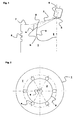
- the rotationally symmetrical piston 1 has a likewise rotationally symmetrical Piston cavity 2 with a combustion chamber wall 9 on. Of the Piston is closed at its top by the piston head 7. In its upper area are annular grooves 8 for the not provided piston rings provided.
- combustion chamber wall 9 and the piston head 7 run on the edge of the combustion chamber 5 together. This transition can be relatively sharp as an edge but also be designed as a rounding.
- the obliquely protruding into the cylinder multi-jet injection nozzle 6 has a coronal arrangement of holes 4.
- the fuel enters as spray cone 3 from each hole and hits the piston.
- the area hit by the spray cone on the piston head 7 is in the drawing with a, the area hit on the combustion chamber wall 9 denoted by b.
- Fig. 2 shows a piston with a vertical and centric in the Combustion chamber 2 projecting multi-jet nozzle 6 and an ideal beam impingement image.
- On the piston head 7 are six areas to see a, whose Size and shape are approximately identical.
- the four non-visible surfaces b be the same on the combustion chamber wall and possibly the same Have area like a. As mentioned above, but already results a huge improvement in combustion, if only at one Bore per injector and cylinder not too big differences exist between the areas a and b.
Landscapes
- Engineering & Computer Science (AREA)
- Chemical & Material Sciences (AREA)
- Combustion & Propulsion (AREA)
- Mechanical Engineering (AREA)
- General Engineering & Computer Science (AREA)
- Dispersion Chemistry (AREA)
- Combustion Methods Of Internal-Combustion Engines (AREA)
- Fuel-Injection Apparatus (AREA)
- Electrical Control Of Air Or Fuel Supplied To Internal-Combustion Engine (AREA)
Description
- Fig. 1
- die schematische Darstellung der Erfindung in einer Brennkraftmaschine mit schrägstehender Vielstrahleinspritzdüse und
- Fig. 2
- eine Aufsicht auf einen Kolben nach Fig. 1 mit einer senkrechtstehenden Vielstrahleinspritzdüse.
Claims (1)
- Verfahren zum Einspritzen von Kraftstoff in eine selbstzündende, direkteinspritzende Brennkraftmaschine mit wenigstens einem Zylinder und einem Kolben (1) mit Brennraummulde (2), Brennraumrand (5) und Kolbenboden (7), wobei der Kraftstoff über eine Vielstrahldüse (6) eingespritzt wird, und der Einspritzzeitpunkt und der Abstand der Vielstrahldüse zum Kolben (1) im oberen Totpunkt so eingestellt werden, dass das Strahlauftreffbild wenigstens eines Strahls der Vielstrahldüse (6) sowohl oberhalb als auch unterhalb des Brennraumrandes (5) liegt, dadurch gekennzeichnet, dass sich die Flächen des Strahlauftreffbildes oberhalb (a) und unterhalb (b) des Brennraumrandes (5) um weniger als 30 % unterscheiden.
Applications Claiming Priority (2)
| Application Number | Priority Date | Filing Date | Title |
|---|---|---|---|
| DE10160561A DE10160561C2 (de) | 2001-12-10 | 2001-12-10 | Selbstzündende direkteinspritzende Brennkraftmaschine |
| DE10160561 | 2001-12-10 |
Publications (3)
| Publication Number | Publication Date |
|---|---|
| EP1326014A2 EP1326014A2 (de) | 2003-07-09 |
| EP1326014A3 EP1326014A3 (de) | 2004-09-08 |
| EP1326014B1 true EP1326014B1 (de) | 2005-08-10 |
Family
ID=7708644
Family Applications (1)
| Application Number | Title | Priority Date | Filing Date |
|---|---|---|---|
| EP02027603A Expired - Lifetime EP1326014B1 (de) | 2001-12-10 | 2002-12-10 | Selbstzündende direkteinspritzende Brennkraftmaschine |
Country Status (3)
| Country | Link |
|---|---|
| EP (1) | EP1326014B1 (de) |
| AT (1) | ATE301770T1 (de) |
| DE (2) | DE10160561C2 (de) |
Families Citing this family (4)
| Publication number | Priority date | Publication date | Assignee | Title |
|---|---|---|---|---|
| DE102004041819B4 (de) * | 2004-08-17 | 2010-12-16 | Alois Dotzer | Mit Pflanzenöl betriebene dieselmotorische Brennkraftmaschine |
| DE102004039764B4 (de) * | 2004-08-17 | 2008-01-31 | Alois Dotzer | Mit Pflanzenöl betriebene dieselmotorische Brennkraftmaschine |
| DE102005035034B4 (de) * | 2005-07-27 | 2007-05-31 | Alois Dotzer | Dieselmotorisch betriebene Brennkraftmaschine |
| CH705573A2 (de) | 2011-09-20 | 2013-03-28 | Beat Frei | Selbstzündende Verbrennungskraftmaschine für den Betrieb mit rohen Pflanzenölen. |
Family Cites Families (5)
| Publication number | Priority date | Publication date | Assignee | Title |
|---|---|---|---|---|
| DE1526313A1 (de) * | 1963-10-10 | 1969-02-06 | Maschf Augsburg Nuernberg Ag | Luftverdichtende selbstzuendende Kolbenbrennkraftmaschine |
| GB2169656B (en) * | 1985-01-15 | 1988-01-20 | Yanmar Diesel Engine Co | Diesel engine piston combustion chamber |
| DE19741380C2 (de) * | 1996-09-20 | 2000-12-28 | Fev Motorentech Gmbh | Hubkolbenbrennkraftmaschine mit Kraftstoffdirekteinspritzung über einen einlaßseitig angeordneten Injektor |
| JPH11117747A (ja) * | 1997-10-14 | 1999-04-27 | Nissan Motor Co Ltd | 直噴式ディーゼルエンジン |
| DE19827463A1 (de) * | 1998-06-19 | 1999-12-23 | Fev Motorentech Gmbh | Direkteinspritzender Dieselmotor mit tumblegestütztem Brennverfahren |
-
2001
- 2001-12-10 DE DE10160561A patent/DE10160561C2/de not_active Expired - Fee Related
-
2002
- 2002-12-10 AT AT02027603T patent/ATE301770T1/de active
- 2002-12-10 EP EP02027603A patent/EP1326014B1/de not_active Expired - Lifetime
- 2002-12-10 DE DE50203875T patent/DE50203875D1/de not_active Expired - Lifetime
Also Published As
| Publication number | Publication date |
|---|---|
| EP1326014A2 (de) | 2003-07-09 |
| EP1326014A3 (de) | 2004-09-08 |
| DE10160561A1 (de) | 2003-06-26 |
| ATE301770T1 (de) | 2005-08-15 |
| DE10160561C2 (de) | 2003-12-24 |
| DE50203875D1 (de) | 2005-09-15 |
Similar Documents
| Publication | Publication Date | Title |
|---|---|---|
| DE112015004524B4 (de) | Kraftstoffeinspritzdüse mit Düse variabler Lochgröße und Sprühwinkel und MHBIB | |
| DE2901210C2 (de) | Verfahren zum Betrieb einer luftverdichtenden, selbstzündenden Brennkraftmaschine | |
| DE102006018973A1 (de) | Laserzündung in einer Vorkammer | |
| EP1290321B1 (de) | Brennstoffeinspritzsystem | |
| DE69214605T2 (de) | Brennkraftmaschine mit verdichtungszündung und direkter einspritzung | |
| DE4020470A1 (de) | Verbrennungskammer fuer eine brennkraftmaschine | |
| DE10122350A1 (de) | Brennstoffeinspritzsystem | |
| DE69400175T2 (de) | Verbrennungskammerstruktur für eine Brennkraftmaschine | |
| DE10160561C2 (de) | Selbstzündende direkteinspritzende Brennkraftmaschine | |
| WO2020038702A1 (de) | Verfahren zum betreiben einer verbrennungskraftmaschine für ein kraftfahrzeug, sowie verbrennungskraftmaschine für ein kraftfahrzeug | |
| DE10354827A1 (de) | Brennstoffeinspritzsystem | |
| EP2815095B1 (de) | Verbrennungskraftmaschine, insbesondere für einen kraftwagen, sowie verfahren zum betreiben einer solchen verbrennungskraftmaschine | |
| EP0083001A1 (de) | Kraftstoffeinspritzsystem für Kraftstoffdirekteinspritzung bei Brennkraftmaschinen | |
| DE694124C (de) | Luftverdichtende Einspritzbrennkraftmaschine mit Selbstzuendung sowie einer schraeg und exzentrisch zur Zylinderachse angeordneten Vorkammer | |
| DE102004053049A1 (de) | Brennkraftmaschine mit Direkteinspritzung | |
| WO2006058640A1 (de) | Brennraum einer selbstzündenden brennkraftmaschine | |
| DE10239555B4 (de) | Brennkraftmaschine mit Direkteinblasung von gasförmigem Kraftstoff und Verfahren zum Betreiben derselben | |
| WO2019214997A1 (de) | Verfahren und vorrichtung zur aufbereitung eines kraftstoff-luft-gemisches | |
| DE10027452C2 (de) | Verfahren zur Gemischbildung mit Prallunterstützung in Brennkraftmaschinen mit Benzin-Direkteinspritzung | |
| DE4136851A1 (de) | Dieselmotor kleinerer leistung | |
| DE382346C (de) | Gesteuerte Einspritzduese zur luftlosen Einspritzung von Brennstoff unmittelbar in den Verbrennungsraum von Verbrennungskraftmaschinen, bei denen sich der Brennstoff an der verdichteten Luft entzuendet | |
| DE586231C (de) | Selbstzuendender Einspritzmotor | |
| DE2537041A1 (de) | Brennkraftmaschine | |
| DE942950C (de) | Selbstzuendende, luftverdichtende Brennkraftmaschine | |
| DE102018207828A1 (de) | Selbstzündende Brennkraftmaschine |
Legal Events
| Date | Code | Title | Description |
|---|---|---|---|
| PUAI | Public reference made under article 153(3) epc to a published international application that has entered the european phase |
Free format text: ORIGINAL CODE: 0009012 |
|
| AK | Designated contracting states |
Designated state(s): AT BE BG CH CY CZ DE DK EE ES FI FR GB GR IE IT LI LU MC NL PT SE SI SK TR |
|
| AX | Request for extension of the european patent |
Extension state: AL LT LV MK RO |
|
| PUAL | Search report despatched |
Free format text: ORIGINAL CODE: 0009013 |
|
| AK | Designated contracting states |
Kind code of ref document: A3 Designated state(s): AT BE BG CH CY CZ DE DK EE ES FI FR GB GR IE IT LI LU MC NL PT SE SI SK TR |
|
| AX | Request for extension of the european patent |
Extension state: AL LT LV MK RO |
|
| 17P | Request for examination filed |
Effective date: 20040802 |
|
| 17Q | First examination report despatched |
Effective date: 20040927 |
|
| GRAP | Despatch of communication of intention to grant a patent |
Free format text: ORIGINAL CODE: EPIDOSNIGR1 |
|
| AKX | Designation fees paid |
Designated state(s): AT BE BG CH CY CZ DE DK EE ES FI FR GB GR IE IT LI LU MC NL PT SE SI SK TR |
|
| GRAS | Grant fee paid |
Free format text: ORIGINAL CODE: EPIDOSNIGR3 |
|
| GRAA | (expected) grant |
Free format text: ORIGINAL CODE: 0009210 |
|
| AK | Designated contracting states |
Kind code of ref document: B1 Designated state(s): AT BE BG CH CY CZ DE DK EE ES FI FR GB GR IE IT LI LU MC NL PT SE SI SK TR |
|
| PG25 | Lapsed in a contracting state [announced via postgrant information from national office to epo] |
Ref country code: IT Free format text: LAPSE BECAUSE OF FAILURE TO SUBMIT A TRANSLATION OF THE DESCRIPTION OR TO PAY THE FEE WITHIN THE PRESCRIBED TIME-LIMIT;WARNING: LAPSES OF ITALIAN PATENTS WITH EFFECTIVE DATE BEFORE 2007 MAY HAVE OCCURRED AT ANY TIME BEFORE 2007. THE CORRECT EFFECTIVE DATE MAY BE DIFFERENT FROM THE ONE RECORDED. Effective date: 20050810 Ref country code: SK Free format text: LAPSE BECAUSE OF FAILURE TO SUBMIT A TRANSLATION OF THE DESCRIPTION OR TO PAY THE FEE WITHIN THE PRESCRIBED TIME-LIMIT Effective date: 20050810 Ref country code: EE Free format text: LAPSE BECAUSE OF FAILURE TO SUBMIT A TRANSLATION OF THE DESCRIPTION OR TO PAY THE FEE WITHIN THE PRESCRIBED TIME-LIMIT Effective date: 20050810 Ref country code: IE Free format text: LAPSE BECAUSE OF FAILURE TO SUBMIT A TRANSLATION OF THE DESCRIPTION OR TO PAY THE FEE WITHIN THE PRESCRIBED TIME-LIMIT Effective date: 20050810 Ref country code: SI Free format text: LAPSE BECAUSE OF FAILURE TO SUBMIT A TRANSLATION OF THE DESCRIPTION OR TO PAY THE FEE WITHIN THE PRESCRIBED TIME-LIMIT Effective date: 20050810 Ref country code: FI Free format text: LAPSE BECAUSE OF FAILURE TO SUBMIT A TRANSLATION OF THE DESCRIPTION OR TO PAY THE FEE WITHIN THE PRESCRIBED TIME-LIMIT Effective date: 20050810 Ref country code: CZ Free format text: LAPSE BECAUSE OF FAILURE TO SUBMIT A TRANSLATION OF THE DESCRIPTION OR TO PAY THE FEE WITHIN THE PRESCRIBED TIME-LIMIT Effective date: 20050810 Ref country code: TR Free format text: LAPSE BECAUSE OF FAILURE TO SUBMIT A TRANSLATION OF THE DESCRIPTION OR TO PAY THE FEE WITHIN THE PRESCRIBED TIME-LIMIT Effective date: 20050810 Ref country code: NL Free format text: LAPSE BECAUSE OF FAILURE TO SUBMIT A TRANSLATION OF THE DESCRIPTION OR TO PAY THE FEE WITHIN THE PRESCRIBED TIME-LIMIT Effective date: 20050810 |
|
| REG | Reference to a national code |
Ref country code: GB Ref legal event code: FG4D Free format text: NOT ENGLISH |
|
| REG | Reference to a national code |
Ref country code: CH Ref legal event code: EP |
|
| REG | Reference to a national code |
Ref country code: IE Ref legal event code: FG4D Free format text: LANGUAGE OF EP DOCUMENT: GERMAN |
|
| REF | Corresponds to: |
Ref document number: 50203875 Country of ref document: DE Date of ref document: 20050915 Kind code of ref document: P |
|
| PG25 | Lapsed in a contracting state [announced via postgrant information from national office to epo] |
Ref country code: SE Free format text: LAPSE BECAUSE OF FAILURE TO SUBMIT A TRANSLATION OF THE DESCRIPTION OR TO PAY THE FEE WITHIN THE PRESCRIBED TIME-LIMIT Effective date: 20051110 Ref country code: DK Free format text: LAPSE BECAUSE OF FAILURE TO SUBMIT A TRANSLATION OF THE DESCRIPTION OR TO PAY THE FEE WITHIN THE PRESCRIBED TIME-LIMIT Effective date: 20051110 Ref country code: BG Free format text: LAPSE BECAUSE OF FAILURE TO SUBMIT A TRANSLATION OF THE DESCRIPTION OR TO PAY THE FEE WITHIN THE PRESCRIBED TIME-LIMIT Effective date: 20051110 Ref country code: GR Free format text: LAPSE BECAUSE OF FAILURE TO SUBMIT A TRANSLATION OF THE DESCRIPTION OR TO PAY THE FEE WITHIN THE PRESCRIBED TIME-LIMIT Effective date: 20051110 |
|
| PG25 | Lapsed in a contracting state [announced via postgrant information from national office to epo] |
Ref country code: ES Free format text: LAPSE BECAUSE OF FAILURE TO SUBMIT A TRANSLATION OF THE DESCRIPTION OR TO PAY THE FEE WITHIN THE PRESCRIBED TIME-LIMIT Effective date: 20051121 |
|
| PG25 | Lapsed in a contracting state [announced via postgrant information from national office to epo] |
Ref country code: CY Free format text: LAPSE BECAUSE OF FAILURE TO SUBMIT A TRANSLATION OF THE DESCRIPTION OR TO PAY THE FEE WITHIN THE PRESCRIBED TIME-LIMIT Effective date: 20051210 |
|
| GBT | Gb: translation of ep patent filed (gb section 77(6)(a)/1977) | ||
| PG25 | Lapsed in a contracting state [announced via postgrant information from national office to epo] |
Ref country code: LU Free format text: LAPSE BECAUSE OF NON-PAYMENT OF DUE FEES Effective date: 20051231 Ref country code: MC Free format text: LAPSE BECAUSE OF NON-PAYMENT OF DUE FEES Effective date: 20051231 Ref country code: BE Free format text: LAPSE BECAUSE OF NON-PAYMENT OF DUE FEES Effective date: 20051231 |
|
| PG25 | Lapsed in a contracting state [announced via postgrant information from national office to epo] |
Ref country code: PT Free format text: LAPSE BECAUSE OF FAILURE TO SUBMIT A TRANSLATION OF THE DESCRIPTION OR TO PAY THE FEE WITHIN THE PRESCRIBED TIME-LIMIT Effective date: 20060110 |
|
| NLV1 | Nl: lapsed or annulled due to failure to fulfill the requirements of art. 29p and 29m of the patents act | ||
| REG | Reference to a national code |
Ref country code: FR Ref legal event code: RN |
|
| REG | Reference to a national code |
Ref country code: IE Ref legal event code: FD4D |
|
| REG | Reference to a national code |
Ref country code: FR Ref legal event code: FC |
|
| PLBE | No opposition filed within time limit |
Free format text: ORIGINAL CODE: 0009261 |
|
| STAA | Information on the status of an ep patent application or granted ep patent |
Free format text: STATUS: NO OPPOSITION FILED WITHIN TIME LIMIT |
|
| 26N | No opposition filed |
Effective date: 20060511 |
|
| EN | Fr: translation not filed | ||
| ET | Fr: translation filed | ||
| EN | Fr: translation not filed | ||
| PG25 | Lapsed in a contracting state [announced via postgrant information from national office to epo] |
Ref country code: CH Free format text: LAPSE BECAUSE OF NON-PAYMENT OF DUE FEES Effective date: 20061231 Ref country code: LI Free format text: LAPSE BECAUSE OF NON-PAYMENT OF DUE FEES Effective date: 20061231 |
|
| REG | Reference to a national code |
Ref country code: CH Ref legal event code: PL |
|
| BERE | Be: lapsed |
Owner name: KAISER, THOMAS Effective date: 20051231 Owner name: GRUBER, GEORG Effective date: 20051231 Owner name: DOTZER, ALOIS Effective date: 20051231 |
|
| PGFP | Annual fee paid to national office [announced via postgrant information from national office to epo] |
Ref country code: FR Payment date: 20081210 Year of fee payment: 7 |
|
| REG | Reference to a national code |
Ref country code: FR Ref legal event code: ST Effective date: 20091130 |
|
| PG25 | Lapsed in a contracting state [announced via postgrant information from national office to epo] |
Ref country code: FR Free format text: LAPSE BECAUSE OF NON-PAYMENT OF DUE FEES Effective date: 20091201 |
|
| PGFP | Annual fee paid to national office [announced via postgrant information from national office to epo] |
Ref country code: AT Payment date: 20101208 Year of fee payment: 9 |
|
| PGFP | Annual fee paid to national office [announced via postgrant information from national office to epo] |
Ref country code: GB Payment date: 20101208 Year of fee payment: 9 |
|
| GBPC | Gb: european patent ceased through non-payment of renewal fee |
Effective date: 20111210 |
|
| PG25 | Lapsed in a contracting state [announced via postgrant information from national office to epo] |
Ref country code: GB Free format text: LAPSE BECAUSE OF NON-PAYMENT OF DUE FEES Effective date: 20111210 |
|
| REG | Reference to a national code |
Ref country code: AT Ref legal event code: MM01 Ref document number: 301770 Country of ref document: AT Kind code of ref document: T Effective date: 20111210 |
|
| PG25 | Lapsed in a contracting state [announced via postgrant information from national office to epo] |
Ref country code: AT Free format text: LAPSE BECAUSE OF NON-PAYMENT OF DUE FEES Effective date: 20111210 |
|
| PGFP | Annual fee paid to national office [announced via postgrant information from national office to epo] |
Ref country code: DE Payment date: 20211109 Year of fee payment: 20 |
|
| REG | Reference to a national code |
Ref country code: DE Ref legal event code: R071 Ref document number: 50203875 Country of ref document: DE |