EP1325764A1 - Atrialer Herzschrittmacher - Google Patents
Atrialer Herzschrittmacher Download PDFInfo
- Publication number
- EP1325764A1 EP1325764A1 EP02090420A EP02090420A EP1325764A1 EP 1325764 A1 EP1325764 A1 EP 1325764A1 EP 02090420 A EP02090420 A EP 02090420A EP 02090420 A EP02090420 A EP 02090420A EP 1325764 A1 EP1325764 A1 EP 1325764A1
- Authority
- EP
- European Patent Office
- Prior art keywords
- atrial
- designed
- control unit
- time
- prevention mode
- Prior art date
- Legal status (The legal status is an assumption and is not a legal conclusion. Google has not performed a legal analysis and makes no representation as to the accuracy of the status listed.)
- Granted
Links
Images


Classifications
-
- A—HUMAN NECESSITIES
- A61—MEDICAL OR VETERINARY SCIENCE; HYGIENE
- A61N—ELECTROTHERAPY; MAGNETOTHERAPY; RADIATION THERAPY; ULTRASOUND THERAPY
- A61N1/00—Electrotherapy; Circuits therefor
- A61N1/18—Applying electric currents by contact electrodes
- A61N1/32—Applying electric currents by contact electrodes alternating or intermittent currents
- A61N1/38—Applying electric currents by contact electrodes alternating or intermittent currents for producing shock effects
- A61N1/39—Heart defibrillators
- A61N1/3956—Implantable devices for applying electric shocks to the heart, e.g. for cardioversion
-
- A—HUMAN NECESSITIES
- A61—MEDICAL OR VETERINARY SCIENCE; HYGIENE
- A61N—ELECTROTHERAPY; MAGNETOTHERAPY; RADIATION THERAPY; ULTRASOUND THERAPY
- A61N1/00—Electrotherapy; Circuits therefor
- A61N1/18—Applying electric currents by contact electrodes
- A61N1/32—Applying electric currents by contact electrodes alternating or intermittent currents
- A61N1/36—Applying electric currents by contact electrodes alternating or intermittent currents for stimulation
- A61N1/362—Heart stimulators
- A61N1/3621—Heart stimulators for treating or preventing abnormally high heart rate
-
- A—HUMAN NECESSITIES
- A61—MEDICAL OR VETERINARY SCIENCE; HYGIENE
- A61N—ELECTROTHERAPY; MAGNETOTHERAPY; RADIATION THERAPY; ULTRASOUND THERAPY
- A61N1/00—Electrotherapy; Circuits therefor
- A61N1/18—Applying electric currents by contact electrodes
- A61N1/32—Applying electric currents by contact electrodes alternating or intermittent currents
- A61N1/36—Applying electric currents by contact electrodes alternating or intermittent currents for stimulation
- A61N1/372—Arrangements in connection with the implantation of stimulators
- A61N1/37211—Means for communicating with stimulators
- A61N1/37252—Details of algorithms or data aspects of communication system, e.g. handshaking, transmitting specific data or segmenting data
- A61N1/37264—Changing the program; Upgrading firmware
-
- A—HUMAN NECESSITIES
- A61—MEDICAL OR VETERINARY SCIENCE; HYGIENE
- A61N—ELECTROTHERAPY; MAGNETOTHERAPY; RADIATION THERAPY; ULTRASOUND THERAPY
- A61N1/00—Electrotherapy; Circuits therefor
- A61N1/18—Applying electric currents by contact electrodes
- A61N1/32—Applying electric currents by contact electrodes alternating or intermittent currents
- A61N1/38—Applying electric currents by contact electrodes alternating or intermittent currents for producing shock effects
- A61N1/39—Heart defibrillators
- A61N1/395—Heart defibrillators for treating atrial fibrillation
Definitions
- the invention relates to a pacemaker that is used to deliver Stimulation pulses to an atrium of a heart is formed.
- Such a pacemaker usually includes a connection for at least one atrial electrode line with which electrical pulses are applied an atrium of a heart transferred to the heart tissue (myocardium) can be deposited in the atrium.
- the connection for the atrial Electrode lead is usually with an atrial Stimulation pulse generator connected, which is designed so that it for Generation of atrial pacing pulses can be controlled that are to be delivered via the atrial lead.
- An (atrial) control unit is provided for the stimulation pulse generator, connected to the atrial stimulation pulse generator and is designed to generate the stimulation pulse generator and Deliver atrial pacing pulses.
- the control unit has an AF prevention mode, in which the atrial control unit Stimulation pulse generator for generating a stimulation pulse sequence which is suitable for preventing atrial fibrillation (AF).
- the pacemaker outlined above is preferably an ICD (implantable cardioverter / defibrillator) with overdrive stimulation for preventive therapy of atrial fibrillation.
- ICD implantable cardioverter / defibrillator
- Such an ICD has usually also via a connection for a ventricular Electrode lead and a stimulation pulse generator for ventricular Stimulation impulses that take effect in the ventricle of a heart.
- Atrial fibrillation affects you significant part of the older population.
- atrial fibrillation affects you significant part of the older population.
- vagal mediated atrial fibrillation and adrinergic atrial fibrillation.
- vagally mediated atrial fibrillation occurs in patients in a relaxed state, for example during digestion, after eating or during the night or early in the morning.
- preliminary Clinical trial results suggest that pacemakers or the Fibrillators that have a preventive pacing mode Have control of atrial fibrillation using so-called overdrivepacing are able to at least the duration of episodes reduce vagal-induced atrial fibrillation.
- Atrial overdrive pacing is based on the thought of lasting stimulate as many atrial contractions as possible and as few as possible Allow natural (spontaneous intrinsic) contractions. Therefore at overdrive stimulation with either a variable or a fixed, increased atrial rate, e.g. 80 to 90 beats per Minute.
- the atrial pacing such that the atrial pacing interval is a length of about 95% of a respective natural (intrinsic) atrial interval equivalent.
- An example of such an adaptive overdrive algorithm is known as the applicant's DDD + algorithm.
- the aim of the present invention is to impair the Lifespan of a pacemaker related to the reduction or reduce prevention of atrial fibrillation.
- the beginning of a pacemaker described type according to the invention provided a timer with the atrial control unit is connected and designed, the AF prevention mode switch on or off depending on the time of day and thereby creating and delivering the atrial fibrillations to activate preventive stimulation pulse sequence depending on the time or to deactivate.
- the invention is based on the knowledge that the above mentioned Vagal-induced atrial fibrillation heaped depending on the time of day occur when the patient is at rest during the digestive period after eating or early in the morning.
- the invention is further based on the finding that atrial fibrillation affect the patient, but not immediately fatal are.
- the invention has Pacemaker has a time memory for the time in which the AF prevention mode is switched on or off.
- the latter pacemaker is preferably designed electrical signals from the atrium of a heart and points an atrial input amplifier and one with it connected detector for atrial fibrillation.
- the latter is with connected to the control unit.
- the control unit is designed so that it Sections of the day of occurrence of atrial fibrillation determined. For this serve her as input signals the signal of the clock and atrial fibrillation detector.
- the generated as the output signal Control unit on times for AF prevention mode and saves this in the time memory.
- the control unit is like this trained that the determined and stored switching times the Corresponds to times of day with frequent occurrence of atrial fibrillation.
- the atrial fibrillation detector can be equipped with a p-wave detector be connected, which is formed with an atrial Contraction associated p-waves in an intracardiac Detect electrocardiogram (EKG).
- the control unit is preferably, at least temporarily, with a Statistics memory connected and acts in such a way with the statistics memory together that times of day are more common for atrial fibrillation can be saved for several different days.
- Such an arrangement with an external, telemetrically integrable Patient device enables complex evaluation of data via the occurrence of atrial fibrillation without the implant, especially in terms of energy consumption.
- a is preferably Implant provided, which has a telemetry unit, the one telemetric connection between the implant and an external one Patient device, in particular between the control unit of the implant and the evaluation unit of the external patient device.
- the time memory is preferably for storing an n bit long Signal formed and cooperates with the control unit such that a predetermined time of day is assigned to each bit of the signal and the state of each signal bit (0 or 1) determines whether the AF prevention mode for the time assigned to the respective bit is switched on.
- a 48-bit memory in which each of the 48 bits for a defined half-hour length of day stands.
- the Signal from the clock generator is a simple address signal for the 48-bit memory his.
- the signal state of the read bit (0 or 1) thus switches immediately turn the AF prevention mode on or off.
- the time memory is closed by a doctor program.
- the time memory is at immediate storage of switch-on and switch-off times and interacts with the control unit such that the AF prevention mode is switched on at a saved switch-on time and remains switched on until the AF prevention mode for is switched off again after the next switch-off time and until remains switched off at the next switch-on time.
- the variant is therefore not a bit of one in the time memory stored signal immediately identifying the input or The AF prevention mode is switched off in the respective bit assigned time of day. Rather are in the time memory directly Times as on or off times (in contrast to the certain Periods characteristic bits) stored.
- Time storage is more memory-intensive, but enables input or Switch-off times that correspond to "crooked" periods and for example, deviate from a half-hour grid.
- This too the latter variant is particularly suitable for an implant with a telemetry unit.
- the determination of the input and Switch-off times then take place analogously to the previously described manner by means of an evaluation unit in one, at least temporarily, telemetrically connected external patient device.
- the pacemaker is preferably designed when the is switched on AF prevention mode atrial stimulation pulse trains in overdrive mode leave.
- the pacemaker is designed in AF prevention mode, Stimulation pulse trains with an increased atrial rate of preferably trigger 80 to 90 pulses per minute.
- FIG 1 are only those for the present in a schematic representation Invention significant components of a pacemaker shown.
- This are a connection 12 for an atrial electrode line 14 with im Embodiment two electrodes 16 and 18.
- the electrode 16 is as Ring electrode formed and the electrode 18 as a pointed electrode.
- the distal The end of the electrode line 14 is for arrangement in the atrium 20 of a heart 22 educated.
- the components of a pacemaker shown include one Stimulation pulse generator 24 for generating atrial Stimulation pulses.
- the stimulation pulse generator 24 is for this purpose the connector 12 connected to the electrode line 14.
- connection 12 with the electrode line 14 Input amplifier 26 connected.
- the atrial input amplifier 26 is designed to be received in the atrium 20 of a heart 22 amplify electrical signals and for further evaluation prepare.
- the input amplifier 26 On the output side is the input amplifier 26 with a p-wave detector 28 connected, which is designed for contraction of the atrium 20th characteristic p-waves in that from the input amplifier 26 prepared, intracardiac electrocardiogram to detect.
- the p-wave detector 28 is on the output side with an AF detector 30 for detection of atrial fibrillations.
- the AF detector 30 determines the frequency of the occurrence of p-waves. This can either done by counting the p-waves into one by one Timer predefined defined period fall. Alternatively, you can use a timer is started for each p-wave by the next one p-wave is stopped, so that the interval between two p-waves is determined. Falls below this interval (e.g. 6 Counting steps) a specified value, this corresponds to an increased atrial Rate and can be evaluated as atrial fibrillation, for example.
- the AF detector 30 inputs corresponding output signal from a memory control unit 32 is supplied. This memory control unit 32 also becomes one Output signal of a clock 34 supplied.
- the Memory control unit 32 can be in different design variants be differently trained.
- the memory control unit 32 trained from the time signal of the clock 34 an address signal to generate for a time memory 36, if on the part of the AF detector 30 a signal characterizing an atrial fibrillation is present.
- the Memory control unit 32 then causes that under the by the The timer-determined address is one bit when the device is switched on state corresponding to the AF prevention mode, for example 1, is saved.
- Atrial one Stimulation control unit 38 also with the timer 34 and the Time memory 36 connected and designed such that they Time memory 36 on the predetermined by the timer 34 Reads out address and depending on the switching status of the bit read out (0 or 1) turns an AF prevention mode on or off. For example the bit under the address of the Time memory 36 "1", the stimulation control unit 38 takes the AF prevention mode and controls the stimulation pulse generator 24 such that this stimulation pulse with an increased atrial rate, for example in overdrive mode.
- Atrial pacing pulses are generated when natural atrial contractions occur (and corresponding p-waves detected by the p-wave detector 28) within a predetermined time, for example after a ventricular event, (VA time) did not occur. Since this is the state of the art Technology corresponds, this is not explained here.
- the time memory 36 is designed in two parts in the latter embodiment.
- the time memory 36 contains in the second part the on and off times for the AF prevention mode.
- the stimulation control unit 38 is designed such that the AF prevention mode is activated when the time given by the timer 34 corresponds to an on-time stored in the second part of the time memory 36. Conversely, the AF prevention mode is deactivated again when a time specified by the timer 34 corresponds to a switch-off time stored in the second part of the time memory 36.
- switch-on and switch-off times are stored alternately in the second part of the time memory 36, so that with each time stored in the time memory 36 the activation of the AF prevention mode is switched from “on” to “off” or vice versa from “off””On” takes place.
- a special bit that differentiates a switch-on time from a switch-off time cannot then be saved. It is also possible to store a bit for each switching time in addition to the time signal, which bit modifies the switching time as the switch-on time or switch-off time.
- a defibrillation control unit is also only for completeness 39 shown on the fibrillation detector 30 in the case of an atrial Fibrillation responds and the stimulation pulse generator 24 to Delivery of an atrial defibrillation pulse.
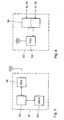
- Figure 2 is a partial representation of a particularly simple Design variant that the first in connection with Figure 1 described embodiment variant is similar.
- the timer 34 ' is at this embodiment variant designed so that it immediately one Address signal for the time memory 36 'generated.
- the Stimulation control unit 38 'then only needs a read signal generate to the time memory 36 'at the current time read the corresponding memory location. As previously described, For example, only a single bit is read out, the state of which, 0 or 1, immediately switches the AF prevention mode on or off.
- a Doctor via an external interface 40 or the AF detector 30 'only one Generate write signal to at the by time predefined memory location the bit to the desired state set, for example "1" for switching on the AF prevention mode.
- FIG. 3 shows an embodiment variant in which the evaluation the times of occurrence of atrial fibrillation and the definition of the on and Switch-off times for the AF prevention mode using an external Patient device 50 takes place.
- the patient device 50 has a to connect telemetric connection to the pacemaker 52.
- the Pacemaker 52 is essentially the same as that already has been described under Figure 1.
- the time memory 34 is divided in two. In part of the time memory 36 "(FIG. 3 the upper one) Part) are the on and off times for the AF prevention mode saved. In the other part of the time memory 36 "(in FIG lower part) are the times of occurrence of atrial fibrillation saved.
- the time memory 36 is with a telemetry transmitter and - receiver 54 connected.
- the patient device 50 which is also sent to the telemetry transmitter 56 that occurs together with the implant-side telemetry transmitter 54 a wireless connection between pacemaker 52 and Patient device 50 allows.
- the patient device 50 also has one Evaluation unit 58, which is connected to a memory 60.
- the arrangement shown in Figure 3 makes it possible in the second part of the Time memory 34 "stored times of occurrence of atrial To transmit fibrillations wirelessly to the patient device 50.
- Patient device 50 can store these times in memory 60 are and by the evaluation unit 58 to form input and Switch-off times for the AF prevention mode can be evaluated.
- the so determined on and off times are with the help of the telemetry transmitter and receivers 54 and 56 from the evaluation unit 58 in the first part of the time memory 34 "of the pacemaker 52.
- This Switch-on and switch-off times then serve the second as in FIG. 1 Design variant described, the switching on and off of the AF prevention mode.
Landscapes
- Health & Medical Sciences (AREA)
- Cardiology (AREA)
- Heart & Thoracic Surgery (AREA)
- Engineering & Computer Science (AREA)
- Biomedical Technology (AREA)
- Nuclear Medicine, Radiotherapy & Molecular Imaging (AREA)
- Radiology & Medical Imaging (AREA)
- Life Sciences & Earth Sciences (AREA)
- Animal Behavior & Ethology (AREA)
- General Health & Medical Sciences (AREA)
- Public Health (AREA)
- Veterinary Medicine (AREA)
- Electrotherapy Devices (AREA)
- Medicines Containing Material From Animals Or Micro-Organisms (AREA)
Abstract
Description
- Figur 1
- eine schematische Blockdarstellung der für die vorliegende Erfindung interessierenden Bestandteile eines Herzschrittmachers
- Figur 2
- Bestandteile einer besonders einfachen Steuerung in schematischer Blockdarstellung
- Figur 3
- ein Blockschaltbild eines implantierbaren Herzschrittmachers der in Figur 1 skizzierten Art mit zusätzlicher Telemetrieeinheit und entsprechendem, externen Patientengerät.
Ebenso ist es möglich, für jeden Schaltzeitpunkt zusätzlich zu dem Uhrzeitsignal ein Bit zu speichern, welches den Schaltzeitpunkt als Einschaltzeitpunkt oder Ausschaltzeitpunkt modifiziert.
Claims (13)
- Herzschrittmacher, ausgebildet zur Abgabe von Stimulationsimpulsen an ein Atrium (20) eines Herzens (22), mit einem Anschluss (12) für eine atriale Elektrodenleitung (14) zur Abgabe elektrischer Impulse an das Atrium (20),
mit einem atrialen Stimulationsimpulsgenerator (24), der mit der Elektrodenleitung (14) verbindbar und ausgebildet ist, über die Elektrodenleitung (14) abzugebende atriale Stimulationsimpulse zu generieren,
mit einer Steuereinheit (38), die mit dem atrialen Stimulationsimpulsgenerator (24) verbunden ist und ausgebildet ist, den Stimulationsimpulsgenerator (24) zum Erzeugen und Abgeben von atrialen Stimulationsimpulsen anzusteuern, wobei die Steuereinheit (38) in einem AF-Präventionsmodus ausgebildet ist, den Stimulationsimpulsgenerator (24) zum Erzeugen einer Stimulationsimpulsfolge anzusteuern, die geeignet ist, einer atrialen Fibrillation (AF) vorzubeugen,
gekennzeichnet durch einen Zeitgeber (34),
der mit der Steuereinheit (38) verbunden und ausgebildet ist, den AF-Präventionsmodus tageszeitabhängig ein- bzw. auszuschalten und dadurch das Erzeugens und Abgeben der atrialen Fibrillationen vorbeugenden Stimulationsimpulsfolgen uhrzeitabhängig zu aktivieren bzw. zu deaktivieren. - Herzschrittmacher nach Anspruch 1, gekennzeichnet durch einen Uhrzeitspeicher (36) für Uhrzeiten des Ein- bzw. Ausschaltens des AF-Präventionsmodus.
- Herzschrittmacher nach Anspruch 2, dadurch gekennzeichnet, dass der Uhrzeitspeicher (36) zum Speichern von n Bit ausgebildet ist und derart mit der Steuereinheit zusammenwirkt, dass jedes Bit einem bestimmten Zeitraum eines Tages zugeordnet und der Zustand eines jeweiligen Bit (0 oder 1) den Aktivierungszustand des AF-Präventionsmodus ("Ein" oder "Aus") für den entsprechenden Tageszeitraum bestimmt.
- Herzschrittmacher nach Anspruch 3, dadurch gekennzeichnet, dass der Uhrzeitspeicher (36) zum Speichern von 48 Bit ausgebildet ist und derart mit der Steuereinheit (38) zusammenwirkt, dass jedes Bit einem jeweils anderen, halbstündigen Tageszeitraum zugeordnet ist.
- Herzschrittmacher nach Anspruch 2, dadurch gekennzeichnet, dass der Uhrzeitspeicher (36) zum unmittelbaren Speichern von Ein- und Ausschaltzeitpunkten ausgebildet ist und derart mit der Steuereinheit (38) zusammenwirkt, dass der AF-Präventionmodus zu einer gespeicherten Einschaltzeit eingeschaltet wird und solange eingeschaltet bleibt, bis der AF-Präventionsmodus zum nächstfolgenden Ausschaltzeitpunkt wieder ausgeschaltet wird und bis zum nächsten Einschaltzeitpunkt ausgeschaltet bleibt.
- Herzschrittmacher nach Anspruch 2, gekennzeichnet durch einen atrialen Eingangsverstärker (26) zur Aufnahme elektrischer Signale des Atriums (20) und einem mit diesem verbundenen Detektor (30) für atriale Fibrillationen, welcher mit der Steuereinheit (32) verbunden ist, wobei die Steuereinheit (32) ausgebildet ist, Tageszeitabschnitte des Auftretens atrialer Fibrillationen mittels der Signale des Uhrzeitgebers (34) und des atrialen Fibrillationsdetektors (30) zu ermitteln.
- Herzschrittmacher nach Anspruch 6, dadurch gekennzeichnet, dass die Steuereinheit (38) dazu ausgebildet ist, aus den Tageszeitabschnitten des Auftretens atrialer Fibrillationen Einschaltzeiten für den AF-Präventionsmodus zu bilden und in dem Uhrzeitspeicher (36) zu speichern.
- Herzschrittmacher nach einem der Ansprüche 2 bis 6, dadurch gekennzeichnet, dass der Herzschrittmacher wenigstens einen Telemetrieempfänger (54) aufweist, der zumindest mittelbar mit dem Uhrzeitspeicher (36) derart verbunden ist, dass Ein- und Ausschaltzeiten telemetrisch in den Uhrzeitspeicher (36) eingeschrieben werden können.
- Herzschrittmacher nach Anspruch 6, gekennzeichnet durch einen Telemetriesender (56), der mit der Steuereinheit (32) und /oder dem Uhrzeitspeicher (36) in Verbindung steht und dazu ausgebildet ist, Tageszeitabschnitte des Auftretens atrialer Fibrillationen an ein externes Patientengerät (50) zu übermitteln.
- Herzschrittmacher nach einem der Ansprüche 1 bis 9, dadurch gekennzeichnet, das die Steuereinheit (38) im AF-Präventionsmodus ausgebildet ist, das Erzeugen und Abgeben einer Stimulationsimpulsfolge mit einer erhöhten atrialen Rate von vorzugsweise 80 bis 90 Impulsen pro Minute auszulösen.
- Herzschrittmacher nach einem der Ansprüche 1 bis 8, dadurch gekennzeichnet, das die Steuereinheit (38) im AF-Präventionsmodus ausgebildet ist, das Erzeugen und Abgeben einer Stimulationsimpulsfolge im Overdrive-Modus auszulösen.
- Externes Patientengerät (50) für einen Herzschrittmacher (52) nach Anspruch 8 und/oder 9, gekennzeichnet durch einen Telemetriesender und -empfänger (56;54), der mit einer Auswerteeinheit (58) und einem Speicher (60) in Verbindung steht, wobei der Speicher (60) zum Speichern von Tageszeitabschnitten des Auftretens atrialer Fibrillationen ausgebildet und die Auswerteeinheit (58) dazu ausgebildet ist, aus den gespeicherten Tageszeitabschnitten des Auftretens atrialer Fibrillationen Ein- und Ausschaltzeiten für den AF-Präventionsmodus des Herzschrittmachers (52) zu bilden.
- Patientengerät (50) nach Anspruch 12, dadurch gekennzeichnet, dass das Patientengerät (50) dazu ausgebildet ist, Ein- und Ausschaltzeiten für den AF-Präventionsmodus des Herzschrittmachers (52) telemetrisch an den Herzschrittmacher (52) zu übermitteln.
Applications Claiming Priority (2)
| Application Number | Priority Date | Filing Date | Title |
|---|---|---|---|
| US34509502P | 2002-01-04 | 2002-01-04 | |
| US345095P | 2002-01-04 |
Publications (2)
| Publication Number | Publication Date |
|---|---|
| EP1325764A1 true EP1325764A1 (de) | 2003-07-09 |
| EP1325764B1 EP1325764B1 (de) | 2006-11-22 |
Family
ID=23353490
Family Applications (1)
| Application Number | Title | Priority Date | Filing Date |
|---|---|---|---|
| EP02090420A Expired - Lifetime EP1325764B1 (de) | 2002-01-04 | 2002-12-20 | Atrialer Herzschrittmacher |
Country Status (3)
| Country | Link |
|---|---|
| EP (1) | EP1325764B1 (de) |
| AT (1) | ATE345837T1 (de) |
| DE (2) | DE10223243A1 (de) |
Citations (3)
| Publication number | Priority date | Publication date | Assignee | Title |
|---|---|---|---|---|
| US5630834A (en) * | 1995-05-03 | 1997-05-20 | Medtronic, Inc. | Atrial defibrillator with means for delivering therapy in response to a determination that the patient is likely asleep |
| EP0904802A2 (de) * | 1997-08-29 | 1999-03-31 | Pacesetter, Inc. | Vorrichtung zur Vermeidung von Vorhof-Fibrillation |
| US5919209A (en) * | 1996-05-13 | 1999-07-06 | Medtronic, Inc. | System and method for myocardial revalidation and therapy by high rate pacing |
Family Cites Families (2)
| Publication number | Priority date | Publication date | Assignee | Title |
|---|---|---|---|---|
| US6058328A (en) * | 1996-08-06 | 2000-05-02 | Pacesetter, Inc. | Implantable stimulation device having means for operating in a preemptive pacing mode to prevent tachyarrhythmias and method thereof |
| DE19958735A1 (de) * | 1999-12-06 | 2001-06-07 | Biotronik Mess & Therapieg | Betriebsverfahren für ein kardiologisches Geräteimplantat, insbesondere einen Herzschrittmacher |
-
2002
- 2002-05-21 DE DE10223243A patent/DE10223243A1/de not_active Withdrawn
- 2002-12-20 DE DE50208768T patent/DE50208768D1/de not_active Expired - Lifetime
- 2002-12-20 EP EP02090420A patent/EP1325764B1/de not_active Expired - Lifetime
- 2002-12-20 AT AT02090420T patent/ATE345837T1/de not_active IP Right Cessation
Patent Citations (3)
| Publication number | Priority date | Publication date | Assignee | Title |
|---|---|---|---|---|
| US5630834A (en) * | 1995-05-03 | 1997-05-20 | Medtronic, Inc. | Atrial defibrillator with means for delivering therapy in response to a determination that the patient is likely asleep |
| US5919209A (en) * | 1996-05-13 | 1999-07-06 | Medtronic, Inc. | System and method for myocardial revalidation and therapy by high rate pacing |
| EP0904802A2 (de) * | 1997-08-29 | 1999-03-31 | Pacesetter, Inc. | Vorrichtung zur Vermeidung von Vorhof-Fibrillation |
Also Published As
| Publication number | Publication date |
|---|---|
| DE10223243A1 (de) | 2003-07-17 |
| EP1325764B1 (de) | 2006-11-22 |
| ATE345837T1 (de) | 2006-12-15 |
| DE50208768D1 (de) | 2007-01-04 |
Similar Documents
| Publication | Publication Date | Title |
|---|---|---|
| EP2060299B1 (de) | Biventrikulärer Herzstimulator | |
| DE69225118T2 (de) | Durch Reizung von einem implantierten Skelettmuskelstransplantat arbeitendes Arrhythmiekontrollgerät | |
| DE60221186T2 (de) | Zweikammer-Herzschrittmachersystem mit einer dynamisch angepassten Interpulse-Verzögerung | |
| DE69619190T2 (de) | Implantierbarer Vorhof-Defibrillator und System mit mehrkanaliger Telemetrie von Elektrogrammen | |
| DE69121038T2 (de) | Einfangsbestätigung mittels einer auf dem Steckergehäuse eines Herzschrittmachers angeordneten neutralen Elektrode | |
| DE60021004T2 (de) | Herzschrittmacher mit einer Einrichtung zur automatischen Schwellwertbestimmung | |
| DE60132407T2 (de) | Implantierbarer Herzschrittmacher mit automatischer Auswahl der Elektrodenanordnung zur Detektion der evozierten Reaktion | |
| DE60122820T2 (de) | Vorrichtung zur Verringerung der Effekte von evozierten Potentialen bei Polarisationsmessungen in einem Herzschrittmachersystem mit automatischer Erfassung des Einfanges | |
| DE60118433T2 (de) | Implantierbare medizinische vorrichtung zur überwachung von kongestiver herzinsuffizienz | |
| DE3587786T2 (de) | Messung des herzschlagintervalls eines stimulierten herzes, sich anpassender herzschrittmacher und betriebsart. | |
| DE60131041T2 (de) | Implantierbare Herzvorrichtung zur Überwachung der Verschlechterung oder Verbesserung von Herzerkrankungen | |
| DE3233718T1 (de) | Extern programmierbarer, implantierbarer herzstimulator | |
| DE60208286T2 (de) | Mehrkammer Herzschrittmacher mit automatischer Fangverifikation zur Reduzierung von echten und durch die Austastzeit induzierten Nichterfassungen, und entsprechendes Verfahren | |
| DE60110962T2 (de) | System zur automatischen Abstimmung des Sicherheitsspielraums für die automatischen Fangerfassung | |
| EP3025759A1 (de) | Mrt-taugliches aktives implantierbares gerät | |
| DE60031640T2 (de) | Vorrichtung zur Erkennung einer natürlichen elektrischen Kohärenz im Herz und zur Verabreichung einer darauf basierenden Therapie | |
| EP1393774A1 (de) | Herzschrittmacher | |
| EP2111892B1 (de) | Antitachykarder Herzstimulator | |
| DE69935743T2 (de) | Aktive implantierbare medizinische Vorrichtung, insbesondere mehrstelliger Herzstimulator, Defibrillator und/oder Kardiovertierer | |
| DE60203318T2 (de) | Vorrichtung zur verringerung der wahrscheinlichkeit von vorhofflimmern | |
| DE69836690T2 (de) | Herzschrittmacher | |
| EP2308558B1 (de) | Biventrikulärer Herzstimulator | |
| EP1325764B1 (de) | Atrialer Herzschrittmacher | |
| EP2111893A1 (de) | Ventrikulärer Herzstimulator | |
| DE102008002293A1 (de) | Antitachykarder Herzstimulator |
Legal Events
| Date | Code | Title | Description |
|---|---|---|---|
| PUAI | Public reference made under article 153(3) epc to a published international application that has entered the european phase |
Free format text: ORIGINAL CODE: 0009012 |
|
| AK | Designated contracting states |
Designated state(s): AT BE BG CH CY CZ DE DK EE ES FI FR GB GR IE IT LI LU MC NL PT SE SI SK TR |
|
| AX | Request for extension of the european patent |
Extension state: AL LT LV MK RO |
|
| 17P | Request for examination filed |
Effective date: 20031009 |
|
| AKX | Designation fees paid |
Designated state(s): AT BE BG CH CY CZ DE DK EE ES FI FR GB GR IE IT LI LU MC NL PT SE SI SK TR |
|
| 17Q | First examination report despatched |
Effective date: 20041223 |
|
| GRAP | Despatch of communication of intention to grant a patent |
Free format text: ORIGINAL CODE: EPIDOSNIGR1 |
|
| RAP1 | Party data changed (applicant data changed or rights of an application transferred) |
Owner name: BIOTRONIK GMBH & CO. KG |
|
| GRAS | Grant fee paid |
Free format text: ORIGINAL CODE: EPIDOSNIGR3 |
|
| GRAA | (expected) grant |
Free format text: ORIGINAL CODE: 0009210 |
|
| AK | Designated contracting states |
Kind code of ref document: B1 Designated state(s): AT BE BG CH CY CZ DE DK EE ES FI FR GB GR IE IT LI LU MC NL PT SE SI SK TR |
|
| PG25 | Lapsed in a contracting state [announced via postgrant information from national office to epo] |
Ref country code: SI Free format text: LAPSE BECAUSE OF FAILURE TO SUBMIT A TRANSLATION OF THE DESCRIPTION OR TO PAY THE FEE WITHIN THE PRESCRIBED TIME-LIMIT Effective date: 20061122 Ref country code: CZ Free format text: LAPSE BECAUSE OF FAILURE TO SUBMIT A TRANSLATION OF THE DESCRIPTION OR TO PAY THE FEE WITHIN THE PRESCRIBED TIME-LIMIT Effective date: 20061122 Ref country code: IE Free format text: LAPSE BECAUSE OF FAILURE TO SUBMIT A TRANSLATION OF THE DESCRIPTION OR TO PAY THE FEE WITHIN THE PRESCRIBED TIME-LIMIT Effective date: 20061122 Ref country code: SK Free format text: LAPSE BECAUSE OF FAILURE TO SUBMIT A TRANSLATION OF THE DESCRIPTION OR TO PAY THE FEE WITHIN THE PRESCRIBED TIME-LIMIT Effective date: 20061122 Ref country code: FI Free format text: LAPSE BECAUSE OF FAILURE TO SUBMIT A TRANSLATION OF THE DESCRIPTION OR TO PAY THE FEE WITHIN THE PRESCRIBED TIME-LIMIT Effective date: 20061122 |
|
| REG | Reference to a national code |
Ref country code: GB Ref legal event code: FG4D Free format text: NOT ENGLISH |
|
| REG | Reference to a national code |
Ref country code: CH Ref legal event code: EP |
|
| REG | Reference to a national code |
Ref country code: SE Ref legal event code: TRGR |
|
| REG | Reference to a national code |
Ref country code: IE Ref legal event code: FG4D Free format text: LANGUAGE OF EP DOCUMENT: GERMAN |
|
| PG25 | Lapsed in a contracting state [announced via postgrant information from national office to epo] |
Ref country code: BE Free format text: LAPSE BECAUSE OF NON-PAYMENT OF DUE FEES Effective date: 20061231 Ref country code: MC Free format text: LAPSE BECAUSE OF NON-PAYMENT OF DUE FEES Effective date: 20061231 |
|
| GBT | Gb: translation of ep patent filed (gb section 77(6)(a)/1977) |
Effective date: 20061207 |
|
| REF | Corresponds to: |
Ref document number: 50208768 Country of ref document: DE Date of ref document: 20070104 Kind code of ref document: P |
|
| PG25 | Lapsed in a contracting state [announced via postgrant information from national office to epo] |
Ref country code: DK Free format text: LAPSE BECAUSE OF FAILURE TO SUBMIT A TRANSLATION OF THE DESCRIPTION OR TO PAY THE FEE WITHIN THE PRESCRIBED TIME-LIMIT Effective date: 20070222 Ref country code: BG Free format text: LAPSE BECAUSE OF FAILURE TO SUBMIT A TRANSLATION OF THE DESCRIPTION OR TO PAY THE FEE WITHIN THE PRESCRIBED TIME-LIMIT Effective date: 20070222 |
|
| PG25 | Lapsed in a contracting state [announced via postgrant information from national office to epo] |
Ref country code: ES Free format text: LAPSE BECAUSE OF FAILURE TO SUBMIT A TRANSLATION OF THE DESCRIPTION OR TO PAY THE FEE WITHIN THE PRESCRIBED TIME-LIMIT Effective date: 20070305 |
|
| ET | Fr: translation filed | ||
| PG25 | Lapsed in a contracting state [announced via postgrant information from national office to epo] |
Ref country code: PT Free format text: LAPSE BECAUSE OF FAILURE TO SUBMIT A TRANSLATION OF THE DESCRIPTION OR TO PAY THE FEE WITHIN THE PRESCRIBED TIME-LIMIT Effective date: 20070423 |
|
| REG | Reference to a national code |
Ref country code: IE Ref legal event code: FD4D |
|
| PLBE | No opposition filed within time limit |
Free format text: ORIGINAL CODE: 0009261 |
|
| STAA | Information on the status of an ep patent application or granted ep patent |
Free format text: STATUS: NO OPPOSITION FILED WITHIN TIME LIMIT |
|
| 26N | No opposition filed |
Effective date: 20070823 |
|
| BERE | Be: lapsed |
Owner name: BIOTRONIK G.M.B.H. & CO. KG Effective date: 20061231 |
|
| PG25 | Lapsed in a contracting state [announced via postgrant information from national office to epo] |
Ref country code: AT Free format text: LAPSE BECAUSE OF NON-PAYMENT OF DUE FEES Effective date: 20061220 |
|
| PG25 | Lapsed in a contracting state [announced via postgrant information from national office to epo] |
Ref country code: GR Free format text: LAPSE BECAUSE OF FAILURE TO SUBMIT A TRANSLATION OF THE DESCRIPTION OR TO PAY THE FEE WITHIN THE PRESCRIBED TIME-LIMIT Effective date: 20070223 |
|
| PG25 | Lapsed in a contracting state [announced via postgrant information from national office to epo] |
Ref country code: EE Free format text: LAPSE BECAUSE OF FAILURE TO SUBMIT A TRANSLATION OF THE DESCRIPTION OR TO PAY THE FEE WITHIN THE PRESCRIBED TIME-LIMIT Effective date: 20061122 |
|
| PG25 | Lapsed in a contracting state [announced via postgrant information from national office to epo] |
Ref country code: TR Free format text: LAPSE BECAUSE OF FAILURE TO SUBMIT A TRANSLATION OF THE DESCRIPTION OR TO PAY THE FEE WITHIN THE PRESCRIBED TIME-LIMIT Effective date: 20061122 Ref country code: LU Free format text: LAPSE BECAUSE OF NON-PAYMENT OF DUE FEES Effective date: 20061220 |
|
| PG25 | Lapsed in a contracting state [announced via postgrant information from national office to epo] |
Ref country code: CY Free format text: LAPSE BECAUSE OF FAILURE TO SUBMIT A TRANSLATION OF THE DESCRIPTION OR TO PAY THE FEE WITHIN THE PRESCRIBED TIME-LIMIT Effective date: 20061122 |
|
| PGFP | Annual fee paid to national office [announced via postgrant information from national office to epo] |
Ref country code: NL Payment date: 20081219 Year of fee payment: 7 |
|
| PGFP | Annual fee paid to national office [announced via postgrant information from national office to epo] |
Ref country code: IT Payment date: 20081224 Year of fee payment: 7 |
|
| REG | Reference to a national code |
Ref country code: NL Ref legal event code: V1 Effective date: 20100701 |
|
| PG25 | Lapsed in a contracting state [announced via postgrant information from national office to epo] |
Ref country code: NL Free format text: LAPSE BECAUSE OF NON-PAYMENT OF DUE FEES Effective date: 20100701 |
|
| PG25 | Lapsed in a contracting state [announced via postgrant information from national office to epo] |
Ref country code: IT Free format text: LAPSE BECAUSE OF NON-PAYMENT OF DUE FEES Effective date: 20091220 |
|
| REG | Reference to a national code |
Ref country code: DE Ref legal event code: R082 Ref document number: 50208768 Country of ref document: DE Representative=s name: RANDOLL, SOEREN, DIPL.-CHEM. UNIV. DR. RER. NA, DE |
|
| REG | Reference to a national code |
Ref country code: DE Ref legal event code: R081 Ref document number: 50208768 Country of ref document: DE Owner name: BIOTRONIK SE & CO. KG, DE Free format text: FORMER OWNER: BIOTRONIK GMBH & CO. KG, 12359 BERLIN, DE Effective date: 20111219 |
|
| PGFP | Annual fee paid to national office [announced via postgrant information from national office to epo] |
Ref country code: GB Payment date: 20121218 Year of fee payment: 11 Ref country code: SE Payment date: 20121217 Year of fee payment: 11 |
|
| PGFP | Annual fee paid to national office [announced via postgrant information from national office to epo] |
Ref country code: FR Payment date: 20130123 Year of fee payment: 11 |
|
| REG | Reference to a national code |
Ref country code: SE Ref legal event code: EUG |
|
| GBPC | Gb: european patent ceased through non-payment of renewal fee |
Effective date: 20131220 |
|
| PG25 | Lapsed in a contracting state [announced via postgrant information from national office to epo] |
Ref country code: SE Free format text: LAPSE BECAUSE OF NON-PAYMENT OF DUE FEES Effective date: 20131221 |
|
| REG | Reference to a national code |
Ref country code: FR Ref legal event code: ST Effective date: 20140829 |
|
| PG25 | Lapsed in a contracting state [announced via postgrant information from national office to epo] |
Ref country code: GB Free format text: LAPSE BECAUSE OF NON-PAYMENT OF DUE FEES Effective date: 20131220 Ref country code: FR Free format text: LAPSE BECAUSE OF NON-PAYMENT OF DUE FEES Effective date: 20131231 |
|
| PGFP | Annual fee paid to national office [announced via postgrant information from national office to epo] |
Ref country code: CH Payment date: 20161222 Year of fee payment: 15 |
|
| PGFP | Annual fee paid to national office [announced via postgrant information from national office to epo] |
Ref country code: DE Payment date: 20170223 Year of fee payment: 15 |
|
| REG | Reference to a national code |
Ref country code: DE Ref legal event code: R119 Ref document number: 50208768 Country of ref document: DE |
|
| REG | Reference to a national code |
Ref country code: CH Ref legal event code: PL |
|
| PG25 | Lapsed in a contracting state [announced via postgrant information from national office to epo] |
Ref country code: DE Free format text: LAPSE BECAUSE OF NON-PAYMENT OF DUE FEES Effective date: 20180703 |
|
| PG25 | Lapsed in a contracting state [announced via postgrant information from national office to epo] |
Ref country code: CH Free format text: LAPSE BECAUSE OF NON-PAYMENT OF DUE FEES Effective date: 20171231 Ref country code: LI Free format text: LAPSE BECAUSE OF NON-PAYMENT OF DUE FEES Effective date: 20171231 |