EP1321721B1 - Air conditioner - Google Patents
Air conditioner Download PDFInfo
- Publication number
- EP1321721B1 EP1321721B1 EP01954451A EP01954451A EP1321721B1 EP 1321721 B1 EP1321721 B1 EP 1321721B1 EP 01954451 A EP01954451 A EP 01954451A EP 01954451 A EP01954451 A EP 01954451A EP 1321721 B1 EP1321721 B1 EP 1321721B1
- Authority
- EP
- European Patent Office
- Prior art keywords
- impeller
- vane
- conditioning apparatus
- air conditioning
- cross flow
- Prior art date
- Legal status (The legal status is an assumption and is not a legal conclusion. Google has not performed a legal analysis and makes no representation as to the accuracy of the status listed.)
- Expired - Lifetime
Links
Images


Classifications
-
- F—MECHANICAL ENGINEERING; LIGHTING; HEATING; WEAPONS; BLASTING
- F04—POSITIVE - DISPLACEMENT MACHINES FOR LIQUIDS; PUMPS FOR LIQUIDS OR ELASTIC FLUIDS
- F04D—NON-POSITIVE-DISPLACEMENT PUMPS
- F04D29/00—Details, component parts, or accessories
- F04D29/26—Rotors specially for elastic fluids
- F04D29/28—Rotors specially for elastic fluids for centrifugal or helico-centrifugal pumps for radial-flow or helico-centrifugal pumps
- F04D29/30—Vanes
-
- F—MECHANICAL ENGINEERING; LIGHTING; HEATING; WEAPONS; BLASTING
- F04—POSITIVE - DISPLACEMENT MACHINES FOR LIQUIDS; PUMPS FOR LIQUIDS OR ELASTIC FLUIDS
- F04D—NON-POSITIVE-DISPLACEMENT PUMPS
- F04D17/00—Radial-flow pumps, e.g. centrifugal pumps; Helico-centrifugal pumps
- F04D17/02—Radial-flow pumps, e.g. centrifugal pumps; Helico-centrifugal pumps having non-centrifugal stages, e.g. centripetal
- F04D17/04—Radial-flow pumps, e.g. centrifugal pumps; Helico-centrifugal pumps having non-centrifugal stages, e.g. centripetal of transverse-flow type
-
- F—MECHANICAL ENGINEERING; LIGHTING; HEATING; WEAPONS; BLASTING
- F04—POSITIVE - DISPLACEMENT MACHINES FOR LIQUIDS; PUMPS FOR LIQUIDS OR ELASTIC FLUIDS
- F04D—NON-POSITIVE-DISPLACEMENT PUMPS
- F04D29/00—Details, component parts, or accessories
- F04D29/66—Combating cavitation, whirls, noise, vibration or the like; Balancing
- F04D29/661—Combating cavitation, whirls, noise, vibration or the like; Balancing especially adapted for elastic fluid pumps
- F04D29/663—Sound attenuation
- F04D29/665—Sound attenuation by means of resonance chambers or interference
-
- F—MECHANICAL ENGINEERING; LIGHTING; HEATING; WEAPONS; BLASTING
- F24—HEATING; RANGES; VENTILATING
- F24F—AIR-CONDITIONING; AIR-HUMIDIFICATION; VENTILATION; USE OF AIR CURRENTS FOR SCREENING
- F24F1/00—Room units for air-conditioning, e.g. separate or self-contained units or units receiving primary air from a central station
- F24F1/0007—Indoor units, e.g. fan coil units
- F24F1/0018—Indoor units, e.g. fan coil units characterised by fans
- F24F1/0025—Cross-flow or tangential fans
-
- F—MECHANICAL ENGINEERING; LIGHTING; HEATING; WEAPONS; BLASTING
- F24—HEATING; RANGES; VENTILATING
- F24F—AIR-CONDITIONING; AIR-HUMIDIFICATION; VENTILATION; USE OF AIR CURRENTS FOR SCREENING
- F24F1/00—Room units for air-conditioning, e.g. separate or self-contained units or units receiving primary air from a central station
- F24F1/0007—Indoor units, e.g. fan coil units
- F24F1/0043—Indoor units, e.g. fan coil units characterised by mounting arrangements
- F24F1/0057—Indoor units, e.g. fan coil units characterised by mounting arrangements mounted in or on a wall
-
- F—MECHANICAL ENGINEERING; LIGHTING; HEATING; WEAPONS; BLASTING
- F24—HEATING; RANGES; VENTILATING
- F24F—AIR-CONDITIONING; AIR-HUMIDIFICATION; VENTILATION; USE OF AIR CURRENTS FOR SCREENING
- F24F1/00—Room units for air-conditioning, e.g. separate or self-contained units or units receiving primary air from a central station
- F24F1/0007—Indoor units, e.g. fan coil units
- F24F1/0059—Indoor units, e.g. fan coil units characterised by heat exchangers
- F24F1/0063—Indoor units, e.g. fan coil units characterised by heat exchangers by the mounting or arrangement of the heat exchangers
-
- F—MECHANICAL ENGINEERING; LIGHTING; HEATING; WEAPONS; BLASTING
- F24—HEATING; RANGES; VENTILATING
- F24F—AIR-CONDITIONING; AIR-HUMIDIFICATION; VENTILATION; USE OF AIR CURRENTS FOR SCREENING
- F24F1/00—Room units for air-conditioning, e.g. separate or self-contained units or units receiving primary air from a central station
- F24F1/0007—Indoor units, e.g. fan coil units
- F24F1/0059—Indoor units, e.g. fan coil units characterised by heat exchangers
- F24F1/0067—Indoor units, e.g. fan coil units characterised by heat exchangers by the shape of the heat exchangers or of parts thereof, e.g. of their fins
-
- F—MECHANICAL ENGINEERING; LIGHTING; HEATING; WEAPONS; BLASTING
- F24—HEATING; RANGES; VENTILATING
- F24F—AIR-CONDITIONING; AIR-HUMIDIFICATION; VENTILATION; USE OF AIR CURRENTS FOR SCREENING
- F24F1/00—Room units for air-conditioning, e.g. separate or self-contained units or units receiving primary air from a central station
- F24F1/0007—Indoor units, e.g. fan coil units
- F24F1/0071—Indoor units, e.g. fan coil units with means for purifying supplied air
- F24F1/0073—Indoor units, e.g. fan coil units with means for purifying supplied air characterised by the mounting or arrangement of filters
-
- F—MECHANICAL ENGINEERING; LIGHTING; HEATING; WEAPONS; BLASTING
- F24—HEATING; RANGES; VENTILATING
- F24F—AIR-CONDITIONING; AIR-HUMIDIFICATION; VENTILATION; USE OF AIR CURRENTS FOR SCREENING
- F24F1/00—Room units for air-conditioning, e.g. separate or self-contained units or units receiving primary air from a central station
- F24F1/0007—Indoor units, e.g. fan coil units
- F24F1/0083—Indoor units, e.g. fan coil units with dehumidification means
-
- F—MECHANICAL ENGINEERING; LIGHTING; HEATING; WEAPONS; BLASTING
- F24—HEATING; RANGES; VENTILATING
- F24F—AIR-CONDITIONING; AIR-HUMIDIFICATION; VENTILATION; USE OF AIR CURRENTS FOR SCREENING
- F24F13/00—Details common to, or for air-conditioning, air-humidification, ventilation or use of air currents for screening
- F24F13/24—Means for preventing or suppressing noise
Definitions
- Fig. 24 is a diagram illustrating the frequency characteristic of noise of an air conditioning apparatus in which the conventional cross flow fan is mounted.
- the singular noise Sm is generated in the impeller 2 of the conventional cross flow fan
- the singular noise Sm is multiplexed, and the frequency characteristic is formed into a sharp pointed shape when the width of the generating frequency fs of the singular noise Sm is around 100[Hz]. This is because the spaces ⁇ between vanes 2b and the next vanes 2b are regular, when the singular noise Sm is generated, the flow rate of air and the state of the detaching vortex are almost regular at the vane 2b.
- a straight line connecting the closest point 3a 1 of the stabilizer 3a to the impeller 2 of the cross flow fan and the center O of the rotating shaft of the impeller is O-3a 1
- a horizontal line passing through the center O of the rotating shaft of the impeller is L0.
- the stabilizer is formed in such a manner as to locate at a place where an acute angle ⁇ 1 formed by the two straight lines O-3a 1 and L0 is between 30 degrees and 70 degrees from the horizontal line L0 as the base in the opposite direction to the rotation of the impeller.
- the ratio of the height H of the main body of the air conditioning apparatus to the outside diameter ⁇ D2 of the impeller 2 is 2.2 or above and 3.0 or below in this embodiment.
- Fig. 37 is a longitudinal cross-sectional view of an air conditioning apparatus according to a further embodiment. It is to be noted that elements other than the cross flow fan 1 of the air conditioning apparatus of this embodiment are the same as those of the air conditioning apparatus and the cross flow fan of Fig. 1 to Fig. 5 discussed above in the preceeding embodiment, therefore the same reference numerals as those of the embodiment are assigned to the elements and the description will be omitted.
- a closest point 3b 1 of the guide wall 3b to the impeller 2 of the cross flow fan is disposed at an upper rear portion of the air conditioning apparatus.
- the guide wall 3b is formed in such a manner that an angle ⁇ 3 formed by a straight line O-3b 1 , which connects the closest point 3b 1 of the guide wall 3b to the impeller and the center O of the rotating shaft of the impeller, and a horizontal line L0, which passes through the center O of the rotating shaft of the impeller, is between 35 degrees to 80 degrees.
- the air inlet side area Fi and the air outlet side area Fo are separated in the cross flow fan. For that reason, if the angle ⁇ 3 is too large, then the guide wall 3b is extended forward to a front portion of the air conditioning apparatus 10 as shown in Fig. 38 , so that the air inlet side area Fi of the impeller becomes narrow. Because the area on the air inlet side becomes narrow, the ventilating resistance becomes high. For that reason, the ventilating characteristic becomes worse, the noise level is aggravated, and the power consumption Wm of the fan motor 5 is increased. In addition to that, the flow rate of the air flow E1 from the back side of the air conditioning apparatus is increased, and the singular noise Sm is easily generated.
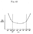
- Fig. 40 is a diagram illustrating a change in the noise level at the same flow rate in a situation where the ⁇ 3 is varied.
- Fig. 41 is a diagram illustrating a change in the power consumption of the fan motor at the same flow rate in a situation where the ⁇ 3 is varied.
- Fig. 42 and Fig. 43 are diagrams illustrating an example of the shape of a vane 2b of the impeller of a cross flow fan to be used as an air blowing means for an air conditioning apparatus according to an embodiment of the present invention.
- Those figures are the cross-sectional view of the vane 2b and the enlarged view of an area in the vicinity of the peripheral end portion A2 of the vane 2b.
- elements other than the vane 2b in this embodiment are the same as those of the air conditioning apparatus and the cross flow fan of Fig. 1 to Fig. 5 discussed above in the first embodiment, therefore the same reference numerals as those of the embodiment are assigned to the elements and the description will be omitted.
- the fixed angle ⁇ is formed at least in such a manner as to be smaller than an angle ⁇ 4 formed by a tangent U4 at the vertex A22 and the straight line O-A22.
- Fig. 45 is a diagram illustrating a shape of a vane 2b of the impeller of a cross flow fan to be used as a air blowing means of an air conditioning apparatus according to a further embodiment of the present invention.
- the figure is an enlarged diagram of an area in the vicinity of the peripheral end portion A2 of the vane 2b.
- elements other than the vane 2b in this embodiment are the same as those of the enlarged views of the vane 2b of the impeller of the cross flow fan shown in Fig. 42 and Fig. 43 discussed above, therefore the same reference numerals as those of the figures are assigned to the elements and the description will be omitted.
- Fig. 49 is a diagram illustrating a shape of a vane 2b of the impeller of a cross flow fan to be used as an air blowing means for an air conditioning apparatus according to a further embodiment of the present invention.
- the figure is a partial cross-sectional view of the impeller 2.
- elements other than the vane 2b in this embodiment are the same as those of the air conditioning apparatus and the cross flow fan of Fig. 1 to Fig. 5 discussed above in the first embodiment, therefore the same reference numerals as those of the embodiment are assigned to the elements and the description will be omitted.
- the vane's peripheral end portion A2 of the vane 2b facing the peripheral surface of the impeller of the cross flow fan is formed by the elastic body. For that reason, there is no fear of cutting the tip of one's finger or damaging fingernails in case of touching by mistake the impeller 2 of the cross flow fan while rotating, when one puts one's hand into the cross flow fan towards the impeller 2 through the air outlet 14 of the air conditioning apparatus.
- the pressure fluctuation that is received at the peripheral end portion A 2 of the vane 2b by the impeller 2 while rotating may be reduced, so that the noise may be lowered.
- the maximum thickness tm near the center of the vane of the impeller of the cross flow fan to the thickness ratio of the thickness of the vane's peripheral end portion t2, which is the minimum thickness and the diameter of the circular-arc shaped vane's peripheral end portion is from above 1.5 to 3.5 the latter upper limit being included.
- the vane 2b is excised along the circle sharing the center with the center of the impeller 2 and having the 2% reduced diameter ⁇ D21 from the diameter ⁇ D2 of the peripheral circle of the ring 2c which is also the outer diameter of the impeller.
- the remaining internal circumferential portion of the impeller is the vane 2ba.
- Vertexes A22 and A23 and an arc A223 are obtained as a result of the vane 2b being excised.
- the straight line connecting the rotating center O of the impeller and the vertex A22 is O-A22
- the straight line connecting the rotating center O of the impeller and the vertex A23 is O-A23.
- straight lines obtained by inclining the vertexes A22 and A23 by the fixed same angle ⁇ on the side of the direction of rotation are U2 and U3, respectively.
- the vane 2b is formed by the vane 2ba and the portion 2bb in a similar shape to a parallelogram.
- the portion 2bb in the similar shape to a parallelogram is enclosed by the two straight lines U2 and U3, the arc A223, and the circle having the diameter ⁇ D22 which is at least smaller than the outside diameter ⁇ D2 of the impeller and larger than the diameter ⁇ D21 mentioned above.
- the portion facing the periphery of the impeller 2 of the vane 2b is not formed in the shape of an edge but formed into the fixed shape of R. Therefore, cleaning is allowed to be done for the impeller without tearing a cloth or cutting a finger while cleaning with soft paper (such as waste).
- the impeller 2 including the rings 2c for supporting the plurality of vanes 2b is formed in most part by resin materials.
- the vane's peripheral end portion A2 is formed by the elastic body 19 such as rubber, for example.
- the pressure fluctuation at the peripheral end portion A2 of the vane 2b that is received by the impeller 2 while rotating may be reduced, so that the noise may be lowered.
Landscapes
- Engineering & Computer Science (AREA)
- Mechanical Engineering (AREA)
- General Engineering & Computer Science (AREA)
- Chemical & Material Sciences (AREA)
- Combustion & Propulsion (AREA)
- Physics & Mathematics (AREA)
- Thermal Sciences (AREA)
- Structures Of Non-Positive Displacement Pumps (AREA)
- Air-Conditioning Room Units, And Self-Contained Units In General (AREA)
Abstract
Description
- The present invention relates to an air conditioning apparatus such as an air conditioner, a dehumidifier and an air purifier, and more particularly to an air conditioning apparatus in which a cross flow fan is mounted to be used as a blowing means.
- Hereafter, a description will be made of an air conditioning apparatus, such as an air conditioner, a dehumidifier and an air purifier, in which a conventional cross flow fan is mounted. An example of the conventional cross flow fan entitled "Indoor Unit for Air Conditioner" is disclosed in Japanese Unexamined Patent Publication No.
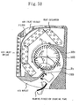
Hei 11-83062 Fig. 50 is a longitudinal cross-sectional view of the main body of an air conditioning apparatus disclosed in Japanese Unexamined Patent Publication No.Hei 11-83062 Fig. 51 is a perspective view of the impeller of a conventional cross flow fan.Fig. 52 is a longitudinal cross-sectional view of the cross flow fan ofFig. 51 .Fig. 53 is a cross-sectional view of a vane shown inFig. 52 .Fig. 54 is a diagram illustrating the frequency characteristic of noise of the air conditioning apparatus in which the conventional cross flow fan is mounted. - With referring to
Figs. 50 ,51 and52 , the conventional cross flow fan is formed by animpeller 101, aguide wall 102, astabilizer 103, and a motor 104. Theimpeller 101 is formed by two ormore units 101a which are connected in the direction of the shaft, each unit being formed by a plurality ofvanes 101b and aring 101c for supporting the plurality of vanes. Theguide wall 102 surrounds theimpeller 101 in such a manner as to cover one side of the peripheral surface of theimpeller 101. Thestabilizer 103 is disposed in such a manner as to face theguide wall 102. The motor 104 rotates and operates theimpeller 101 as indicated by an arrow J. - According to the air conditioning apparatus in which the thus configured conventional cross flow fan is mounted, as shown in
Fig. 50 , air is sucked in through a detachable front facing grill and a detachable top facing inlet grill, then dust is removed from the air by using a filter, and thereafter the air is heated or refrigerated by means of a heat exchanger which is formed in such a manner as to surround theimpeller 101. Heat-exchanged air after passing through the heat exchanger is sucked into theimpeller 101, passes through a row of vanes on the side of the heat exchanger, and then is blown off again through a row of vanes on the side of an air outlet. Then, the air is blown off through the air outlet to the room by blowing-direction changing vanes, including up/down vanes and left/right vanes, changing the blowing direction of the air. Thus, the room is air-conditioned. - With referring now to the
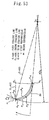
vane 101b in a cross-sectional shape shown inFig. 53 , a reference numeral A20 denotes a tip of a vane's peripheral end portion A2 in the shape of a circular arc of thevane 101b. A reference numeral A10 denotes a tip of a vane's internal circumferential end portion A1 in the shape of a circular arc of thevane 101b. A reference mark O denotes the center of the rotating shaft of theimpeller 101, and a reference numeral O1 denotes the center of a camber line P0 formed into a single circular arc of thevane 101b. A reference numeral P2 denotes a pressure face of thevane 101b on a side facing the direction of rotation of the impeller, and a reference numeral P3 denotes a suction surface opposing to the pressure face P2. O-A20 indicates a first straight line connecting the tip of the vane's peripheral end portion A20 of thevane 101b and the center O. O1-A20 indicates a second straight line connecting the tip of the vane's peripheral end portion A20 of thevane 101b and the center O1 of the camber line P0. Further, a reference mark n denotes a first perpendicular of the first straight line O-A20 to the tip of the vane's peripheral end portion A20, and a reference mark m denotes a second perpendicular of the second straight line O1-A20 to the tip of the vane's peripheral end portion A20. An exit angle β2 is an acute angle formed by the first perpendicular and the second perpendicular. - With referring to the cross flow fan, for example, by expanding the outside diameter ϕD2 of the
impeller 101 in a similar shape, the flow rate is increased and the noise level is lowered. However if the flow rate is increased and the noise level is lowered in such a manner, singular noise S1 is generated in a low frequency range as shown in the diagram illustrating the frequency characteristic of noise ofFig. 54 . In addition to that, there may be a case where the noise level at the same flow rate is increased and a resultant atmosphere to the ear is made worse. For that reason, according to the conventional cross flow fan, the singular noise S1 is tried to be reduced by setting the exit angle β2 of thevane 101b to 23 degrees or less. Furthermore, by setting the exit angle β2 to 18 degrees or more, the noise level at the same flow rate is lowered and a resultant atmosphere to the ear is controlled not to be aggravated. - Furthermore, by forming the
vane 101b such that tmax/tmin = 1.3-1.5, a blowing performance at a high flow rate may be obtained, where tmax denotes a maximum thickness of thevane 101b and tmin denotes the thickness of the vane's peripheral end portion, which is the thickness of a portion of thevane 101 excluding a roundish portion at a mounting end of thevane 101 on the vane's peripheral side. In addition to that, this also allows to obtain an interior unit of an air conditioner which has less opportunities of generating the singular noise in a low frequency range. - However, according to an air conditioning apparatus using the conventional cross flow fan disclosed in Japanese Unexamined Patent Publication No.
Heill-83062 impeller 101 becomes high due to a decrease in the fin pitch of the heat exchanger, or dust accumulated on the filter, a circulating vortex C1 caused near thestabilizer 103, which is a typical phenomenon of a cross flow fan, may develop from a solid circle to a broken bold circle. Then, air after passing through the heat exchanger flows towards a cross flow vortex having a lower pressure, and then sucked into theimpeller 101 as indicated by the arrow ofFig. 50 . As a result, in an area F1, the flow of air may be detached from thevane 101b, and then an air turbulent vortex G1 may be generated at a rear portion of thevane 101b. Consequently, as shown in the diagram illustrating the frequency characteristic of noise ofFig. 54 , there may be a case where the singular noise Sm having a frequency width fs is generated in a low frequency range of around 40 to 80 percent of the generation frequency of the rotation noise (NZ sound) depending upon the number of vanes Z and the rotational frequency N [r.p.m] of theimpeller 101. For that reason, a jarring noise other than the rotational noise may be generated, which produces an aggravated atmosphere to the ear, and this has been a problem. - Furthermore, because the vane's exit angle β2 is reduced, thereby narrowing a vane's distance, when the flow of air passes between vanes, a resistance occurs. As a result, the shaft output for operating the impeller is increased, which increases the power consumption of the motor.
-
EP-A-0 915 258 andJP-A-08 16687 claim 1 which follows, wherein the ratio of an outside diameter ϕD2 of the impeller to a height H of a main body of the apparatus is comprised within the range defined in said preamble. - Hence, the present invention has been devised to solve the above described problems, and an object is to obtain an air conditioning apparatus which provides a favourable atmosphere to the ear and saves energy by controlling noise not to be aggravated even if the suction resistance of the impeller becomes high due to such a noise and dust during its operation, and further, by minimising the generation of the singular noise in a low frequency range and the rotation noise, and minimising the power consumption of the motor.
- The air conditioning apparatus of the invention is defined by the appended claims.
- The air conditioning apparatus according to the invention has a cross-flow fan which includes an impeller being formed by a plurality of vanes and a ring for supporting the plurality of vanes, and a heat exchanger. Then, the cross-flow fan includes a nozzle portion which is formed by a stabiliser and an outlet, and a guide wall. A ratio H/ϕD2 of a height H of a main body of the air conditioning apparatus to an outside diameter ϕD2 of the impeller is between 2.2 and 3.0 the limits being included.
- An air conditioning apparatus according to the invention is characterised by an impeller of a cross-flow fan in which a vane's exit angle β2 is between 23 degrees and 30 degrees.
- An air conditioning apparatus according to the invention is characterised by an impeller of a cross-flow fan in which a ratio tm/t2 of a maximum thickness tm of the vane of the impeller of the cross-flow fan to a minimum thickness t2 of the vane is from above 1.5 to 3.5, the upper limit being included when the minimum thickness t2 is a diameter of a peripheral end portion of the vane in a shape of a circular arc so as to reduce singular noise generated in a frequency range lower than that of rotation noise, and a thickness of the vane is gradually varied.
- An air conditioning apparatus according to an embodiment of the invention is characterized by an impeller of a cross flow fan in which a maximum thickness of a vane of the impeller of the cross flow fan is between 0.9 mm and 1.5 mm when a minimum thickness t2 of the vane of the impeller of the cross flow fan is between 0.2 mm and 0.6 mm and the minimum thickness t2 of the vane is a diameter of a peripheral end portion of the vane in a shape of a circular arc.
- An air conditioning apparatus according to an embodiment of the invention is characterized by an impeller of a cross flow fan in which the maximum thickness of the vane of the impeller of the cross flow fan is between 0.9 mm and 1.5 mm when the minimum thickness t2 of the vane of the impeller of the cross flow fan is between 0.2 mm and 0.6 mm and the minimum thickness t2 is the diameter of the peripheral end portion of the vane in the shape of the circular arc.
- An air conditioning apparatus according to an embodiment of the invention is characterized by an impeller of a cross flow fan in which the vane is formed into a shape of an edge obtained by cutting the vane along a circle passing through a peripheral end portion of the vane where a center of the circle is a center O of a rotating shaft of the impelled.
- An air conditioning apparatus according to an embodiment of the invention is characterized by an impeller of a cross flow fan in which the vane is formed into a shape of an edge obtained by cutting the vane along a circle passing through the peripheral end portion of the vane where a center of the circle is a center O of a rotating shaft of the impeller.
- An air conditioning apparatus according to an embodiment of the invention is characterized by an impeller of a cross flow fan in which the plurality of vanes is fitted with an irregular space between the vanes in pitch.
- An air conditioning apparatus according to an embodiment of the invention is characterized by an impeller of a cross flow fan in which the plurality of vanes of the impeller of the cross flow fan is fitted with an irregular space between the vanes in pitch.
- An air conditioning apparatus according to an embodiment of the invention is characterized by a cross flow fan in which the stabilizer is formed at a lower front portion of the air conditioning apparatus in such a manner that an acute angle formed by a straight line, and a horizontal line is between 30 degrees and 70 degrees when the straight line connects a closest point of the stabilizer to the impeller of the cross flow fan to a center O of a rotating shaft of the impeller and a horizontal line and the horizontal line passes through the center O of the rotating shaft of the impeller.
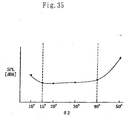
- An air conditioning apparatus according to an embodiment of the invention is characterized by the stabilizer which is formed in such a manner that an acute angle formed by two straight lines is between 15 degrees and 40 degrees when the two straight lines connect a center O of the impeller of the cross flow fan, respectively, to a closest point of the stabilizer to the impeller of the cross flow fan and to a lower portion of the stabilizer.
- An air conditioning apparatus according to an embodiment of the invention is characterized by a cross flow fan in which the guide wall is formed at an upper rear portion of the air conditioning apparatus in such a manner that an angle θ3 formed by a straight line and a horizontal line is between 35 degrees and 80 degrees when the straight line connects a closest point of the guide wall to the impeller of the cross flow fan and a center of a rotating shaft of the impeller and the horizontal line passes through the center O of the rotating shaft of the impeller,
- An air conditioning apparatus according to an embodiment of the invention is characterized by an impeller of a cross flow fan in which a shape of a peripheral end portion of the vane extends to a peripheral side of the impeller in a shape of an inclining parallelogram forward in a direction of rotation of the impeller, but the shape is not projecting outside a periphery of the ring for supporting the plurality of vanes, in a cross-sectional view at right angles to a line of a rotating shaft of the impeller of the cross flow fan.
- An air conditioning apparatus according to an embodiment of the invention is characterized by an impeller of a cross flow fan in which two vertexes of a peripheral end portion of the vane facing a peripheral side of the impeller are formed in a fixed shape of R when the vertexes extend to the peripheral side of the impeller in a shape of parallelogram.
- An air conditioning apparatus according to an embodiment of the invention is characterized by an impeller of a cross flow fan in which each of the plurality of vanes of the impeller of the cross flow fan is inclined by a fixed angle to a rotating shaft of the cross flow fan.
- An air conditioning apparatus according to an embodiment of the invention is characterized by an impeller of a cross flow fan in which a peripheral end portion of the vane of the impeller of the cross flow fan is formed by an elastic body.
-
-
Fig. 1 is an external view illustrating the structure of an air conditioning apparatus according to a first embodiment of the present invention. -
Fig. 2 is a partial cross-sectional view of the air conditioning apparatus ofFig. 1 . -
Fig. 3 is a longitudinal cross-sectional view of the air conditioning apparatus ofFig. 1 . -
Fig. 4 is a perspective view of a cross flow fan inFig. 1 . -
Fig. 5 is a longitudinal cross-sectional view of the cross flow fan ofFig. 4 . -
Fig. 6 is a diagram illustrating the relationship between a ratio H/ϕD2 of the outside diameterϕD2 of an impeller to the height H of the main body and the noise level SPL[dBA] at the same flow rate Q[m3/min]. -
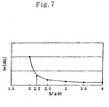
Fig. 7 is a diagram illustrating the relationship between the ratio H/ϕD2 and a maximum level of singular noise Sw[dBA]. -
Fig. 8 is a diagram illustrating a shape of avane 2b of the impeller of a cross flow fan to be used as an air blowing means for an air conditioning apparatus of the present invention. -
Fig. 9 is a diagram illustrating a state of a vane's peripheral end portion A2 of thevane 2b of theimpeller 2 according to the air conditioning apparatus of this invention in a case where an exit angle β2 is too large. -
Fig. 10 is a diagram illustrating the relationship between the vane's exit angle β2 and the motor power consumption Wm[W] according to the air conditioning apparatus of this invention. -
Fig. 11 is a diagram illustrating a shape of avane 2b of the impeller of a cross flow fan to be used as an air blowing means for an air conditioning apparatus of the present invention. -
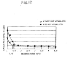
Fig. 12 is a diagram illustrating changes in the level of the singular noise Sw when a thickness ratio tm/t2 is varied in the cases of afilter 12 with and without dust being accumulated. -
Fig. 13 is a diagram illustrating changes in the noise level SPL[dBA] at the same flow rate in the cases of thefilter 12 with and without dust being accumulated. -
Fig. 14 is a diagram illustrating a shape of avane 2b of the impeller of a cross flow fan to be used as an air blowing means for an air conditioning apparatus of an embodiment of the present invention. -
Fig. 15 is a diagram illustrating a state of the suction flow of air at the vane's peripheral end portion A2 of a conventional impeller according to the air conditioning apparatus of this invention. -
Fig. 16 is a diagram illustrating a change in the power consumption of afan motor 5 when a vane's minimum thickness is varied according to the air conditioning apparatus of this invention. -
Fig. 17 is a diagram illustrating a state in which minute pieces of dust, being left unremoved through a filter, are accumulated on the tip A20 of the vane's peripheral end portion of theimpeller 2 according to the air conditioning apparatus of this invention. -
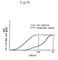
Fig. 18 is a diagram illustrating the operating time and the air flow drop rate at the same rotational frequency of each case of the conventional cross flow fan and the cross flow fan of the air conditioning apparatus of this invention. -
Fig. 19 is a diagram illustrating a basic form of the shape of avane 2b of theimpeller 2 of a cross flow fan to be used as an air blowing means for an air conditioning apparatus of an embodiment of the present invention. -
Fig. 20 is an enlarged view of a tip A20 of the vane's peripheral end portion obtained by changing the basic form of the shape of the tip A20 of the vane's peripheral end portion ofFig. 19 . -
Fig. 21 is a diagram illustrating a state of air flow at the circular-arc shaped vane's peripheral end portion A20 of aconventional vane 2b according to the air conditioning apparatus of this invention. -
Fig. 22 is a diagram illustrating the power consumption Wm[W] of thefan motor 5 for operating an impeller of a cross flow fan in each case of the conventional cross flow fan and the cross flow fan of the air conditioning apparatus of this invention in comparison. -
Fig. 23 is a longitudinal cross-sectional view of animpeller 2 of a cross flow fan to be used as an air blowing means for an air conditioning apparatus of an embodiment of the present invention. -
Fig. 24 is a diagram illustrating the frequency characteristic of noise of an air conditioning apparatus in which a conventional cross flow fan is mounted according to the air conditioning apparatus of this invention. -
Fig. 25 is a diagram illustrating the frequency characteristic of noise of the air conditioning apparatus in which the cross flow fan of this invention is mounted. -
Fig. 26 is a diagram illustrating a state in which a trailing vortex G2 of apipe 13a is directly sucked into theimpeller 2, whenpipes 13b of aheat exchanger 13 are close to theimpeller 2, according to the air conditioning apparatus of this invention. -
Fig. 27 is a diagram illustrating the relationship in the power consumption of the fan motor for operating a cross flow fan at the same flow rate between the conventional cross flow fan and the inventive cross flow fan according to the air conditioning apparatus of this invention. -
Fig. 28 is a longitudinal cross-sectional view of an air conditioning apparatus according to an embodiment of the present invention. -
Fig. 29 is a schematic diagram of the air conditioning apparatus of this invention illustrating a case where an acute angle θ1 is more than 70 degrees, the acute angle θ1 being formed by a straight line 0-3a1, which connects aclosest point 3a1 of a stabilizer to the impeller of the cross flow fan to thecenter 0 of the rotating shaft of the impeller, and a horizontal line L0, which passes through thecenter 0 of the rotating shaft of the impeller. -
Fig. 30 is a diagram illustrating the frequency characteristic of noise of an air conditioning apparatus in which the conventional cross flow fan is mounted according to this invention. -
Fig. 31 is a diagram illustrating a change in the singular noise level Sw when the acute angle θ1 is varied according to the air conditioning apparatus of this invention. -
Fig. 32 is a schematic diagram of the air conditioning apparatus of this invention illustrating a case where the acute angle θ1 is small. -
Fig. 33 is a diagram illustrating the relationship between the acute angle θ1 and the noise level, the acute angle θ1 being formed by the straight line 0-3a1 which connects theclosest point 3a1 of the stabilizer to the impeller of the cross flow fan to thecenter 0 of the rotation shaft of the impeller and the horizontal line L which passes through thecenter 0 of the rotating shaft of the impeller. -
Fig. 34 is a longitudinal cross-sectional view of an air conditioning apparatus according to an embodiment of the present invention. -
Fig. 35 is a diagram illustrating the relationship between an acute angle θ2 and the noise level, the acute angle θ2 being formed by two straight lines 0-3a1 and 0-3a2 connecting aclosest point 3a1 of astabilizer 3a to an impeller and alower portion 3a2 of the stabilizer, respectively, according to the air conditioning apparatus of this invention. -
Fig. 36 is a diagram illustrating the relationship between the acute angle θ2 and the power consumption Wm[W] of the fan motor according to the air conditioning apparatus of this invention. -
Fig. 37 is a longitudinal cross-sectional view of an air conditioning apparatus according to an embodiment of the present invention. -
Fig. 38 is a schematic diagram of the air conditioning apparatus of this invention illustrating a case where an angle θ3 is large, the angle θ3 being formed by a straight line 0-3b1 and a horizontal line L0, the straight line 0-3b1 connecting aclosest point 3b1 of aguide wall 3b to the impeller to thecenter 0 of the rotating shaft of the impeller and the horizontal line L0 passing through thecenter 0 of the rotating shaft of the impeller. -
Fig. 39 is a schematic diagram of the air conditioning apparatus of this invention illustrating a case where the angle θ3 is small. -
Fig. 40 is a diagram illustrating a change in the noise level at the same flow rate when the angle θ3 is varied, in a case where theclosest point 3b1 of theguide wall 3b to theimpeller 2 of the cross flow fan is disposed in an upper rear portion of the air conditioning apparatus, and the angle θ3 is formed by the straight line 0-3b1, connecting theclosest point 3b1 of aguide wall 3b to the impeller to thecenter 0 of the rotating shaft of the impeller, and the horizontal line L0 passing through thecenter 0 of the rotating shaft of the impeller. -
Fig. 41 is a diagram illustrating a change in the power consumption of the fan motor at the same flow rate when the angle θ3 is varied according to the air conditioning apparatus of this invention. -
Fig. 42 is a partial cross-sectional view of a vane of the impeller of a cross flow fan to be mounted in an air conditioning apparatus according to an embodiment of the present invention. -
Fig. 43 is an enlarged view of an area in the vicinity of the vane's peripheral end portion ofFig. 42 . -
Fig. 44 is a diagram illustrating the flow of air between the vanes when each vane is formed into the shape of this invention. -
Fig. 45 is an enlarged view of an area in the vicinity of the vane's peripheral end portion of the impeller of a cross flow fan to be mounted in an air conditioning apparatus according to an embodiment of the present invention. -
Fig. 46 is a perspective view of the impeller of a cross flow fan to be mounted in an air conditioning apparatus according to an embodiment of the present invention. -
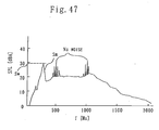
Fig. 47 is a diagram illustrating the frequency characteristic of an air conditioning apparatus in which the impeller of the conventional cross flow fan is mounted. -
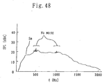
Fig. 48 is a diagram illustrating the frequency characteristic of the air conditioning apparatus in which the impeller of the cross flow fan of this embodiment is mounted. -
Fig. 49 is a partial cross-sectional view of the impeller of a cross flow fan to be mounted in an air conditioning apparatus according to an embodiment of the present invention. -
Fig. 50 is a longitudinal cross-sectional view of a conventional air conditioning apparatus. -
Fig. 51 is a perspective view of the impeller of the cross flow fan of the conventional air conditioning apparatus. -
Fig. 52 is a longitudinal cross-sectional view of the cross flow fan of the conventional air conditioning apparatus. -
Fig. 53 is a cross-sectional view of a vane of the cross flow fan of the conventional air conditioning apparatus. -
Fig. 54 is a diagram illustrating the frequency characteristic of noise of the air conditioning apparatus in which the conventional cross flow fan is mounted. - Hereafter, descriptions will be made in detail of the embodiments of the air conditioning apparatus of the present invention with reference to the drawings.
-
Fig. 1 is an external view illustrating the structure of an air conditioning apparatus according to this invention.Fig. 2 is a partial cross-sectional view of the air conditioning apparatus of this invention.Fig. 3 is a longitudinal cross-sectional view of the air conditioning apparatus of this invention. - With referring to
Fig. 1 ,Fig. 2 andFig. 3 , areference numeral 10 denotes the main body of the air conditioning apparatus of this invention the height of which is H.A reference numeral 10a denotes a housing. Areference numeral 11a denotes a front air inlet grille and areference numeral 11b denotes an upper air inlet grille. Areference numeral 12 denotes a filter for removing floating dust in room air. Areference numeral 13 denotes a heat exchanger, areference numeral 13a denotes an aluminum fin and areference numeral 13b denotes a pipe. Areference 14 denotes an air outlet. Areference numeral 15 denotes blowing-direction changing vanes, areference numeral 15a denotes a left/right vane and areference numeral 15b denotes an up/down vane. Areference numeral 1 denotes a cross flow fan. Areference numeral 2 denotes the impeller of the cross flow fan. Areference numeral 3a denotes a stabilizer. Areference numeral 3b denotes a guide wall. Areference numeral 4 denotes a nozzle. Areference numeral 5 denotes a fan motor for operating theimpeller 2. Areference numeral 6 denotes a rotating shaft. Areference numeral 8 denotes a box for electric equipment. - The thus configured main body of the
air conditioning apparatus 10 is installed on awall 17 of aroom 18. The outside of the main body is formed by thehousing 10a and the detachable frontair inlet grille 11a. Further, thehousing 10a is formed by the upperair inlet grille 11b, theguide wall 3b near the back of the main body, and thenozzle 4 in a lower front portion of the main body. Theair outlet 14 is formed by thenozzle 4 and theguide wall 3b. Thenozzle 4 is formed in such a manner as to incorporate thestabilizer 3. - Besides, the front
air inlet grille 11a, the upperair inlet grille 11b and thefilter 12, and furthermore, theheat exchanger 13 are disposed on the air inlet side of thecross flow fan 1. Then, the box forelectric equipment 8 stores an electrical substrate for controlling the blowing-direction changing vanes 15 and thefan motor 5. -
Fig. 4 is a perspective view of the cross flow fan.Fig. 5 is a longitudinal cross-sectional view of the cross flow fan, where ϕD2 indicates the outside diameter of the impeller. Referring now to thecross flow fan 1 shown inFig. 4 andFig. 5 , areference numeral 2a denotes impeller units, areference numeral 2b denotes a vane of theimpeller 2, and areference numeral 2c denotes a ring of theimpeller 2. Thecross flow fan 1 is formed by theimpeller 2, theguide wall 3b and thestabilizer 3a. Theimpeller 2 is formed by connecting a plurality ofimpeller units 2a in the direction of the shaft, each impeller unit being formed by a plurality ofvanes 2b and thering 2c for supporting the plurality of vanes. Theguide wall 3b surrounds theimpeller 2 in such a manner as to cover one side of the peripheral surface of the impeller for guiding the flow of air blown off from theimpeller 2 to theair outlet 14. Thestabilizer 3a is placed in such a manner as to face theguide wall 3b for controlling the position of a circulating vortex C1 which is generated inside theimpeller 2 of the cross flow fan. Theimpeller 2 rotates and operates around the center of therotating shaft 6 in the direction indicated by an arrow J. Still more, in this and the following embodiments, in a case where a magnesium alloy, for example, is used as a material for theimpeller 2, the impeller will become recyclable. - Under this condition, an operation is to be started. When the
impeller 2 of thecross flow fan 1 is rotated and operated by thefan motor 5 as indicated by the arrow J ofFig. 2 , air in theroom 18 is sucked in through the frontair inlet grille 11a and the upperair inlet grille 11b, then passes through thefilter 12 where floating dust in the room air is removed, then is refrigerated or heated by theheat exchanger 13, and then sucked into theimpeller 2. The air blown off from theimpeller 2 is blown off upward/downward and leftward/rightward into theroom 18 through the up/downvane 15b and the left/right vane 15a, respectively, provided at theair outlet 14. - In the case of no change being made with the height H of the
main body 10 of the thus described air conditioning apparatus, as the outside diameter ϕD2 of the impeller corresponding to the outside diameter of the ring of theimpeller 2 of the cross flow fan becomes larger, the noise level is lowered at the same flow rate. In addition, the static air pressure of theimpeller 2 becomes high. Therefore, even if the ventilating resistance is added on the air inlet side, the fan characteristic does not becomes worse easily. However, if the outside diameter ϕD2 of the impeller is too large, an interference occurs with theheat exchanger 13. Besides, the length L14 of theair outlet 14 becomes too short for the fan, and the flow of blown air becomes unstable. As a result, surging may be caused for the worst so that the noise level is increased. In addition to that, the air of theroom 18 flows backwards towards theair outlet 14, so that dew is condensed when cooling. Furthermore, it causes the detachment of the flow of air on the surface of thevane 2b, which causes such singular noise Sm in a low frequency range as that discussed with reference toFig. 54 in the conventional example. To the contrary, in the case that the outside diameter ϕD2 of the impeller is too small, it is required to rotate the impeller at a high rate in order to supply blowing wind at the same flow rate as that described above. In that case, theimpeller 2 vibrates, thereby shaking the air conditioning apparatus, which may cause a fear of the air conditioning apparatus falling down in the end. In addition to that, the noise level is severely increased. Furthermore, an increase in the pressure of theimpeller 2 is small, therefore if a resistance is added on the air inlet side, a decrease in the flow rate becomes extreme at the same rotational frequency. Still more, as the outside diameter ϕD2 of the impeller is increased or reduced, the size of theguide wall 3b and the size of thenozzle 4 incorporating thestabilizer 3a is increased or reduced, respectively, in a similar manner. - Hence, there is an optimal range for the relationship between the height H of the main body of the
air conditioning apparatus 10 and the outside diameter ϕD2 of the impeller. -
Fig. 6 is a diagram illustrating the noise level SPL[dBA] in relation to the ratio H/ϕD2 of the outside diameter ϕD2 of the impeller to the height H of the main body. As shown inFig. 6 , if the ratio H/ϕD2 is 2.2 or above and 3.0 or below, the noise level changes only a little. - In the case of applying the ratio of the above ratio H/ϕD2 to an air conditioning apparatus, it is particularly effective to apply the ratio to a wall-mounted type of an air conditioning apparatus. The height H of the main body of the air conditioning apparatus should be between 240 mm and 310 mm, therefore it is low in height and compact, which is one of the product values of the air conditioning apparatus.
- Furthermore, if the outside diameter ϕD2 of the impeller is too large and the ratio H/ϕD2 is too small, then the suction resistance of the
impeller 2 becomes high, so that the singular noise Sm is generated. - As shown in a diagram illustrating the ratio H/ϕD2 and a maximum noise level Sw[dBA] of the singular noise Sw of
Fig. 7 , when H/ϕD2 is 2.2 or more, the singular noise Sw is small, therefore a favorable atmosphere may be achieved to the ear. - Still more, a mixture of plastic and grass fiber, for example, used as a material for a conventional impeller may not be used for the
impeller 2. If a magnesium alloy is used, instead, as the magnesium alloy is more refractory, the strength of the product will be preserved even if a heating source such as a heater is placed near theimpeller 2. - AS aforementioned, when cooling, dew does not condense at the air outlet, the noise level does not change much, and shaking is only small. In addition to that, no singular noise is generated, and even if the resistance in the passage of air on the air inlet side becomes high, the flow rate may be lowered only a little. Thus, an air conditioning apparatus which is reliable with a stable operation and silent with a favorable atmosphere to the ear may be obtained.
-
Fig. 8 is a diagram illustrating the shape of avane 2b of the impeller of a cross flow fan to be used as an air blowing means for an air conditioning apparatus of the present invention. It is to be noted that elements other than thevane 2b of this embodiment are the same as those of the air conditioning apparatus and the cross flow fan ofFig. 1 to Fig. 5 discussed in the first embodiment, therefore the same reference numerals as those of the embodiment are assigned to those elements and then the description will be omitted. - With referring to a cross-sectional shape of the
vane 2b ofFig. 8 , a reference numeral A20 denotes a tip of a vane's peripheral end portion A2 of thevane 2b. A reference numeral A10 denotes a tip of a vane's internal circumferential end portion A1 of thevane 2b. A reference mark O denotes the center of the rotating shaft of theimpeller 2 of the cross flow fan, and a reference numeral O1 denotes the center of a camber line P0 formed in a single circular arc, the camber line being the center line of the thickness of thevane 2b. A reference numeral P2 denotes a pressure face of thevane 2b on a side facing the direction of rotation of the impeller, and a reference numeral P3 denotes a suction surface opposing to the pressure face P2. Further, O-A20 indicates a first straight line connecting the tip of the vane's peripheral end portion A20 of thevane 2b and the center O, and O1-A20 indicates a second straight line connecting the tip of the vane's peripheral end portion A20 of thevane 2b and the center O1 of the camber line P0. Further, a reference mark m denotes a first perpendicular of the first straight line O-A20 to the tip of the vane's peripheral end portion A20, a reference mark n denotes a second perpendicular line of the second straight line O1-A20 to the tip of the vane's peripheral end portion A20. An exit angle β2 is an acute angle formed by the first perpendicular and the second perpendicular. - Furthermore, the ratio H/ϕD2 of the height H of the main body of the air conditioning apparatus to the outside diameter ϕD2 of the impeller is 2.2 or above and 3.0 or below.
- As the exit angle β2 of
Fig. 8 becomes larger, a distance between vanes δ is more extended, where the distance δ is the diameter of a circle coming in contact with the respective surfaces of the pressure face P2 of thevane 2b and the suction surface P3 of thenext vane 2b. Consequently, when the flow of air passes between vanes, the ventilating resistance becomes low. Therefore, the shaft power for operating theimpeller 2 is reduced, which allows the power consumption of the motor to be reduced. - However, if the exit angle β2 is too large, then the suction air of the
impeller 2 detaches at the peripheral end portion A2 of thevane 2b as shown inFig. 9 , and the impeller is caused to stall. As a result, the movement of theimpeller 2 of the cross flow fan becomes unstable, which may cause the wind blown off from theair outlet 14 of theair conditioning apparatus 10 to flow backwards into theimpeller 2. - To the contrary, if the exit angle β2 is too small, then the distance between vanes δ is reduced. Consequently, when the flow of air passes between the vanes, the ventilating resistance becomes high. As a result, the shaft power for operating the
impeller 2 is increased, thereby increasing the power consumption of the motor. - Hence, there is an optimal range for the exit angle β2 to achieve the situation that the movement of the
impeller 2 become stable and the shaft power is reduced so that the power consumption of the motor is reduced. -
Fig. 10 shows the relationship between the exit angle β2 of the vane and the power consumption Wm[W] of the motor. As shown inFig. 10 , if the exit angle β2 is higher than 23 degrees up to 30 degrees included an energy-saving air conditioning apparatus which achieves a reduced consumption of the motor power may be obtained. -
Fig. 11 is a diagram illustrating the shape of avane 2b of the impeller of a cross flow fan to be used as an air blowing means for an air conditioning apparatus according to the present invention. It is to be noted that elements other than thevane 2b in this embodiment are the same as those of the air conditioning apparatus and the cross flow fan ofFig. 1 to Fig. 5 discussed above, therefore the same reference numerals as those of the embodiment are assigned to the elements and then the description will be omitted. - With referring to a cross-sectional shape of the
vane 2b ofFig. 11 , the reference numeral A20 denotes the tip of the vane's peripheral end portion A2 of thevane 2b. The reference numeral A10 denotes the tip of the vane's internal circumferential end portion A1 of thevane 2b. The reference mark O denotes the center of the rotating shaft of theimpeller 2 of the cross flow fan, and the reference numeral O1 denotes the center of the camber line P0 formed into a single circular arc, the camber line being the center line of thevane 2b in the direction of the thickness. The reference numeral P2 denotes the pressure face of thevane 2b on a side facing the direction of rotation of the impeller, and the reference numeral P3 denotes the suction surface opposing to the pressure face P2. Further, O-A20 indicates the first straight line connecting the tip of the vane's peripheral end portion A20 of thevane 2b and the center O, and O1-A20 indicates the second straight line connecting the tip of the vane's peripheral end portion A20 of thevane 2b and the center O1 of the camber line P0. Further, the reference mark n denotes a first perpendicular of the first straight line O-A20 to the tip of the vane's peripheral end portion A20, the reference mark m denotes a second perpendicular line of the second straight line O1-A20 to the tip of the vane's peripheral end portion A20. The exit angle β2 is an acute angle formed by the first perpendicular and the second perpendicular. Furthermore, the maximum thickness of thevane 2b around the center is tm and the thickness of the vane's peripheral end portion, which is the diameter of the circular-arc shaped vane's end portion A2 and the minimum thickness, is t2. - Further, the ratio H/ϕD2 of the height H of the main body of the air conditioning apparatus to the outside diameter ϕD2 of the impeller is between 2.2 and 3.0 the limits being included. Furthermore, the exit angle β2 is within a range from higher than 23 degrees up to 30 degrees included.
- With referring to
Fig. 11 , the maximum thickness tm is not changed and the thickness of the vane's peripheral end portion t2, which is the vane's minimum thickness, is reduced. Otherwise, the thickness t2 of the vane's peripheral end portion, which is the vane's minimum thickness, is not changed, and the vane's maximum thickness tm is increased. In other words, a thickness ratio tm/t2, which is the ratio of the vane's maximum thickness tm to the vane's minimum thickness t2, is increased. - However, in the case of the
vane 2b of theimpeller 2 of the conventional cross flow fan, the thickness ratio tm/t2 of which is small and the exit angle β2 of which is 23 degrees or more as shown inFig. 53 , if the ventilating resistance is increased due to such as dust accumulating on thefilter 12 of thebody 10 of the air conditioning apparatus, when thevane 2b passes through an area F1 on the air inlet side of theimpeller 2 and also in an upper front portion of the main body of theair conditioning apparatus 10, detachment is caused at the vane's peripheral end portion A2 of thevane 2b influenced by an inflow of suction air from the back side of theair conditioning apparatus 10. Then, a detaching vortex G1 is generated in the vicinity of the vane's suction surface P3, and also the flow rate is increased in the vicinity of the pressure face P2 of thenext vane 2b. This causes singular noise Sm having a broad frequency band in a low frequency range to be generated as shown inFig. 54 . - As discussed above in this invention, by increasing the vane's thickness ratio tm/t2, the curvature of the vane's suction surface P3 is increased, which makes it difficult to detach. As a result, the rate of flow between the
vane 2b and thenext vane 2b becomes flat. In such a situation, no singular noise Sm will be generated. - However, if the thickness ratio tm/t2 is too large, the distance δ between vanes, which is the diameter of a circle coming in contact with both of the
vane 2b and thenext vane 2b, becomes narrow, and the ventilating resistance between the vanes is increased. As a result, the noise level at the same flow rate becomes aggravated. Hence, there is an optimal range for the thickness ratio. -
Fig. 12 is a diagram illustrating a change in the level Sw[dBA] of the singular noise Sm when the thickness ratio tm/t2 is varied in the case of no dust accumulated on thefilter 12 and in the case of dust accumulated on thefilter 12.Fig. 13 is a diagram illustrating a change in the noise level SPL[dBA] at the same flow rate when the thickness ratio tm/t2 is varied, in the cases of thefilter 12 with and without dust accumulated, which is similar to the diagram ofFig. 12 . - With referring to
Fig. 12 , in the case of no dust accumulated on thefilter 12, if the thickness ratio is 1.4 or more, then the singular noise Sm becomes low noise. In the case of dust accumulated on thefilter 12, if the thickness ratio is 1.5 or more, the singular noise becomes low noise. Further, with reference toFig. 13 , when thefilter 12 has no dust accumulated, if the thickness ratio is 1.4 or above and 3.5 or below, the noise level is low. With dust accumulated, if the thickness ratio is 1.5 or above and 4.0 or below, the noise level is low. - Thus, according to
Fig. 12 andFig. 13 , if the thickness ratio tm/t2 is above 1.5 to 3.5, the upper limit being included the singular noise Sm becomes low noise, and the noise level is not aggravated. - As a result, even if the ventilating resistance is increased due to such as dust accumulated on the
filter 12 of the air conditioning apparatus, an air conditioning apparatus which provides a favorable atmosphere to the ear may be obtained. -
Fig. 14 is a diagram illustrating the shape of avane 2b of the impeller of a cross flow fan to be used as an air blowing means for an air conditioning apparatus according to an embodiment of the present invention. It is to be noted that elements other than thevane 2b in this embodiment are the same as those of the air conditioning apparatus and the cross flow fan ofFig. 1 to Fig. 5 discussed above in the first embodiment, therefore the same reference numerals as those of the embodiment are assigned to the elements and the description will be omitted. - With referring to a cross-sectional shape of the
vane 2b ofFig. 14 , the reference numeral A20 denotes the tip of the vane's peripheral end portion A2 of thevane 2b. The reference numeral A10 denotes the tip of the vane's internal circumferential end portion A1 of thevane 2b. The reference mark O denotes the center of the rotating shaft of theimpeller 2 of the cross flow fan, and the reference numeral O1 denotes the center of the camber line P0 formed into a single circular arc, the camber line being the center line of thevane 2b in the direction of the thickness. The reference numeral P2 denotes the pressure face of thevane 2b on a side facing the direction of rotation of the impeller, and the reference numeral P3 denotes the suction surface opposing to the pressure face P2. Further, O-A20 indicates the first straight line connecting the tip of the vane's peripheral end portion A20 of thevane 2b and the center O, and O1-A20 indicates the second straight line connecting the tip of the vane's peripheral end portion A20 of thevane 2b and the center O1 of the camber line P0. Further, the reference mark n denotes the first perpendicular of the first straight line O-A20 to the tip of the vane's peripheral end portion A20, the reference mark m denotes the second perpendicular line of the second straight line O1-A20 to the tip of the vane's peripheral end portion A20. The exit angle β2 is an acute angle formed by the first perpendicular and the second perpendicular. Furthermore, a maximum thickness of thevane 2b around the center is tm and the thickness of a vane's peripheral end portion, which is the diameter of the circular-arc shaped vane's end portion A2 and a minimum thickness, is t2. - With reference to the
impeller 2 of a cross flow fan having the ratio H/φD2 of the outside diameter φD2 of theimpeller 2 of the cross flow fan to the height H of the air conditioning apparatus between 2.2 and 3.0 the limits being included, according to the impeller of the conventional cross flow fan, the vane's maximum thickness tm is between 0.9 mm and 1.5 mm, and the vane's minimum thickness t2, which is the diameter of the circular-arc shaped vane's peripheral end portion, is 0.64 mm. According to theimpeller 2 of the cross flow fan to be mounted in theair conditioning apparatus 10 of this invention, the vane's minimum thickness t2, which is the diameter of the circular-arc shaped vane's peripheral end portion, is between 0.2 mm and 0.5 mm. Thus, by making the thickness t2 of the vane's peripheral end portion at least thinner than that of the conventional case, the stagnation of the flow of suction air is reduced at the vane's peripheral end portion A2 as shown inFig. 15 , which allows to reduce the loss. As a result, the shaft power for operating theimpeller 2 by thefan motor 5 is reduced, which allows to reduce the power consumption of thefan motor 5 as shown inFig. 16. Fig. 16 is a diagram illustrating the relationship between the vane's minimum thickness t2 and the motor power consumption Wm[W]. - Furthermore, if the
air conditioning apparatus 10 operates for a long time so that theimpeller 2 is rotated and operated for a long time, minute dust which has left unremoved by thefilter 12 is accumulated on the vane's peripheral end portion A2 of theimpeller 2 as shown inFig. 17 . Consequently, the distance between vanes δ is reduced, and the flow rate Q[m3/min] in the same fan rotational frequency is decreased as the operating time passes.Fig. 18 is a diagram illustrating the operating time and the air flow drop rate ΔQ in the same rotational frequency in the case of the conventional cross flow fan and in the case of the cross flow fan of this invention. As shown inFig. 18 , by making the thickness t2 of the vane's peripheral end portion of the impeller thinner than that of the conventional case, the air flow drop rate in the same operating time may be minimized. As a result, such a problem may be solved that although the air conditioning apparatus has been operating for quite a long time, it does not still get warm enough when heating, and it does not still get cool enough when cooling. In addition to that, a cleaning cycle tc[hour] may become longer than the cleaning cycle tc0[hour] of the conventional case. Consequently, the frequency of cleaning may be reduced. - Thus, by forming the vane as described above in this invention, an energy-saving and highly reliable air conditioning apparatus having low power consumption may be obtained.
-
Fig. 19 is a diagram illustrating a basic vane form of the shape of avane 2b of theimpeller 2 of a cross flow fan to be used as an air blowing means for an air conditioning apparatus according to an embodiment of the present invention.Fig. 20 is an enlarged view of a vane's peripheral end portion A20 of this embodiment which has a change in the shape of the vane's peripheral end portion A20 in the basic vane form ofFig. 19 . It is to be noted that elements other than thevane 2b in this embodiment are the same as those of the air conditioning apparatus and the cross flow fan ofFig. 1 to Fig. 5 discussed above in the first embodiment, therefore the same reference numerals as those of the embodiment are assigned to the elements and the description will be omitted. - With referring to a cross-sectional shape of the
vane 2b ofFig. 19 , which is the basic vane form of this embodiment, the reference numeral A20 denotes the tip of the vane's peripheral end portion A2 of thevane 2b. The reference numeral A10 denotes the tip of the vane's internal circumferential end portion A1 of thevane 2b. The reference mark O denotes the center of the rotating shaft of theimpeller 2 of the cross flow fan, and the reference numeral O1 denotes the center of the camber line P0 formed into a single circular arc, the camber line being the center line of thevane 2b in the direction of the thickness. The reference numeral P2 denotes the pressure face of thevane 2b on a side facing the direction of impeller rotation, and the reference numeral P3 denotes the suction surface opposing to the pressure face P2. Further, O-A20 indicates the first straight line connecting the tip of the vane's peripheral end portion A20 of thevane 2b and the center O, and O1-A20 indicates the second straight line connecting the tip of the vane's peripheral end portion A20 of thevane 2b and the center O1 of the camber line P0. Further, the reference mark n denotes the first perpendicular of the first straight line O-A20 to the tip of the vane's peripheral end portion A20, the reference mark m denotes the second perpendicular line of the second straight line O1-A20 to the tip of the vane's peripheral end portion A20. The exit angle β2 is an acute angle formed by the first perpendicular and the second perpendicular. - According to this embodiment, the
vane 2b is formed into a sharp edge at the vane's peripheral end portion A2. This shape is obtained by excising thevane 2b ofFig. 19 along a circle passing through the tip A20 of the vane's peripheral end portion, the center of the circle being the center O of the rotating shaft of theimpeller 2 as shown inFig. 20 . - Thus, by forming the
vane 2b as described above in this invention, such stagnation of air flow caused at the tip A20 of the vane's peripheral end portion as that shown in a state of air flow at the circular-arc shaped vane's peripheral end portion A2 of theconventional vane 2b ofFig. 21 is reduced, and the loss is reduced. For that reason, the shaft power for operating theimpeller 2 is more reduced. As a result, the power consumption of the motor may be minimized as shown in a diagram illustrating the power consumption Wm[W] of thefan motor 5 for operating the impeller of the cross flow fan in each case of the conventional example and this invention for comparison. Consequently, a highly energy-saving air conditioning apparatus may be obtained with the power consumption being reduced. -
Fig. 23 is a longitudinal cross-sectional view of anair conditioning apparatus 10 and theimpeller 2 of a cross flow fan of this invention. The ratio H/ϕD2 of the height H of the main body of the air conditioning apparatus to the outside diameter ϕD2 of the impeller is 2.2 or above and 3.0 or below. Spaces λ between thevanes 2b of theimpeller 2 are irregular in pitch (λ1, λ2, λ3, ...). The cross-sectional shape of thevane 2b of theimpeller 2 of the cross flow fan ofFig. 23 is the shape discussed in the first embodiment, for example. It is to be noted that elements other than theimpeller 2 of the cross flow fan of this embodiment are the same as those of the air conditioning apparatus and the cross flow fan ofFig. 1 to Fig. 5 discussed above in the first embodiment, therefore the same reference numerals as those of the embodiment are assigned to the elements and the description will be omitted. -
Fig. 24 is a diagram illustrating the frequency characteristic of noise of an air conditioning apparatus in which the conventional cross flow fan is mounted. For example, in a case where the singular noise Sm is generated in theimpeller 2 of the conventional cross flow fan, the singular noise Sm is multiplexed, and the frequency characteristic is formed into a sharp pointed shape when the width of the generating frequency fs of the singular noise Sm is around 100[Hz]. This is because the spaces λ betweenvanes 2b and thenext vanes 2b are regular, when the singular noise Sm is generated, the flow rate of air and the state of the detaching vortex are almost regular at thevane 2b. - However, according to the air conditioning apparatus in which the cross flow fan of this invention is mounted, as shown in
Fig. 23 , the spaces λ between thevanes 2b are irregular in pitch. Therefore, when the singular noise Sm is generated at eachvane 2b, the flow rate of air and the state of a detaching vortex at thevane 2b differ from others. As a result, as shown in a diagram illustrating the frequency characteristic of noise of the air conditioning apparatus in which the cross flow fan of this invention is mounted ofFig. 25 , the singular noise Sm is dispersed. The width of the generating frequency fs of the singular noise Sm becomes broadband. Furthermore, the generating level Sw[dBA] of the singular noise Sm is lowered, and then the singular noise disappears from the diagram of the frequency characteristic, and cannot be heard in the end. - Furthermore, as shown in
Fig. 26 , in a case where thepipes 13b of theheat exchanger 13 are closely disposed to theimpeller 2, the trailing vortexes G2 of thepipes 13a are directly sucked into theimpeller 2. In that case, rotational noise (NZ sound) is also generated by an instantaneous pressure fluctuation caused at the vane's peripheral end portion A2 of thevane 2b. - In such a case, as shown in the diagrams of
Fig. 24 andFig.25 illustrating the frequency characteristic of the air conditioning apparatus of the conventional example and that of this embodiment, respectively, in the case of theimpeller 2 of the conventional cross flow fan, because an instantaneous lift fluctuation at the vane's peripheral end portion A2 is the same at eachvane 2b, the rotational noise is multiplexed, therefore a peak level becomes high in a narrow band. However, if the space λ between thevanes 2b is irregular in pitch, then the instantaneous lift fluctuation at the vane's peripheral end portion A2 is dispersed. As a result, the generating frequency of the rotational noise is dispersed and not multiplexed. Consequently, the peak level becomes low. - With further reference to the conventional cross flow fan in which the
vanes 2b are fitted at regular intervals, if gaps δs and δG between theimpeller 2 and the closest point of thestabilizer 3a to the impeller and the closest point of theguide wall 3b to the impeller, respectively, are small, then the rotational noise (NZ sound) is generated by the instantaneous pressure fluctuation in those gaps. However, by fitting thevanes 2b in the irregular pitch according to this embodiment, the instantaneous lift fluctuation at the vane's peripheral end portion A2 is dispersed. As a result, the generating frequency of the rotational noise is dispersed and not multiplexed, so that the peak level becomes low. For that reason, the gaps δs and δG can be minimized until the peak level becomes the same as that of the conventional case, so that the static air pressure of theimpeller 2 may be raised. As a result, a fan rotational frequency N[r.p.m] at the same flow rate Q[m3/min] may be lowered. Consequently, the power consumption may be reduced as shown in a diagram illustrating the relationship in the power consumption Wm[W] of the fan motor at the same flow rate Q[m3/min] ofFig. 27 . - Thus, by forming the impeller of the cross flow fan as discussed above in this embodiment, the singular noise and the rotational noise may become low, and in addition, the power consumption of the fan motor may be reduced. Consequently, an energy-saving as well as silent air conditioning apparatus which provides a favorable atmosphere to the ear may be obtained.
-
Fig. 28 is a longitudinal cross-sectional view of an air conditioning apparatus according to a further embodiment of this invention. It is to be noted that the main part of the configuration of the air conditioning apparatus of this embodiment is the same as that discussed with reference toFig. 1 to Fig. 5 in the first embodiment. - With referring to
Fig. 28 , thereference numeral 10 denotes the main body of the air conditioning apparatus of this invention the height of which is H. Thereference numeral 10a denotes the housing. Thereference numeral 11a denotes the front air inlet grille and thereference numeral 11b denotes the upper air inlet grille. Thereference numeral 12 denotes the filter for removing dust. Thereference numeral 13 denotes the heat exchanger, thereference numeral 13a denotes the aluminum fin and thereference numeral 13b denotes the pipe. Thereference 14 denotes the air outlet. Thereference numeral 15 denotes the blowing-direction changing vane, thereference numeral 15a denotes the left/right vane and thereference numeral 15b denotes the up/down vane. Thereference numeral 1 denotes the cross flow fan. Thereference numeral 2 denotes the impeller of the cross flow fan. Thereference numeral 3a denotes the stabilizer. Thereference numeral 3b denotes the guide wall. Thereference numeral 4 denotes the nozzle. - The outside of the main body of the thus configured
air conditioning apparatus 10 is formed by thehousing 10a and the detachable frontair inlet grille 11a. Further, thehousing 10a is formed by the upperair inlet grille 11b, theguide wall 3b near the back, and thenozzle 4 at the lower front portion. Theair outlet 14 is formed by thenozzle 4 and theguide wall 3b. Furthermore, thenozzle 4 is formed in such a manner as to incorporate thestabilizer 3. - Further, on the air inlet side of the
cross flow fan 1, the frontair inlet grille 11a, the upperair inlet grille 11b and the filter are disposed, and theheat exchanger 13 is also disposed. - It is to be noted that the ratio of the height H of the main body of the air conditioning apparatus to the outside diameter ϕD2 of the
impeller 2 between 2.2 and 3.0 the limits being included. - Referring now to the air conditioning apparatus thus configured, a straight line connecting the
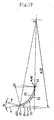
closest point 3a1 of thestabilizer 3a to theimpeller 2 of the cross flow fan and the center O of the rotating shaft of the impeller is O-3a1, and a horizontal line passing through the center O of the rotating shaft of the impeller is L0. In such a case, the stabilizer is formed in such a manner as to locate at a place where an acute angle θ1 formed by the two straight lines O-3a1 and L0 is between 30 degrees and 70 degrees from the horizontal line L0 as the base in the opposite direction to the rotation of the impeller. -
Fig. 29 shows a conventional air conditioning apparatus in which the acute angle θ1 is more than 70 degrees, and theclosest point 3a1 of the stabilizer to theimpeller 2 of the cross flow fan is disposed at a lower portion of the air conditioning apparatus. In this case, a circulating vortex C1 moves downwards, so that an air inlet side area Fi is expanded. However, a suction air flow E1 flows into an area F1 located on the air inlet side of theimpeller 2 and also in an upper front portion of the main body of theair conditioning apparatus 10. For that reason, when thevane 2b passes through the area F1, air may easily detach at the vane's peripheral end portion A2 of thevane 2b. For that reason, if the ventilating resistance is increased due to such as dust accumulated on thefilter 12, in particular, a detaching vortex G1 is generated in the vicinity of the suction surface P3 of the vane. In addition to that, the flow rate in the vicinity of the pressure face P2 of the followingvane 2b is increased. As a result, as shown inFig. 30 , the singular noise Sm having a broad frequency band is generated in a low frequency range. - In a diagram illustrating a change in the singular noise level Sw[dBA] in relation to the θ1 of
Fig. 31 , if θ1 is at least 70 degrees or less, there will be no problem with the singular noise Sm. - Further, as shown in
Fig. 32 , in a case where the acute angle θ1 is 30 degrees or less, the singular noise Sm is reduced, but the air inlet side area Fi is too narrow, therefore the flow rate of suction air is increased. As a result, as shown inFig. 33 , the noise level SPL[dBA] at the same flow rate is increased rapidly. - According to
Fig. 31 andFig. 33 , when a straight line connecting theclosest point 3a1 of thestabilizer 3a to theimpeller 2 of the cross flow fan and the center O of the rotating shaft of the impeller is O-3a1, and a horizontal line passing through the center O of the rotating shaft of the impeller is L0, if the acute angle θ1 formed by the two straight lines O-3a1 and L0 is 30 degrees or above and 70 degrees or below, the singular noise becomes low noise and the noise level is low. - Thus, by forming the
stabilizer 3a as discussed above, a low-noise air conditioning apparatus which provides a favorable atmosphere to the ear without generating the singular noises is made possible. -
Fig. 34 is a longitudinal cross-sectional view of an air conditioning apparatus according to a further embodiment. It is to be noted that the main part of the configuration of the air conditioning apparatus of this embodiment is the same as that of the air conditioning apparatus and the cross flow fan discussed above with reference toFig. 28 , therefore the same reference numerals as those of the preceeding embodiment are assigned to elements and the description will be omitted. - It is further to be noted that the ratio of the height H of the main body of the air conditioning apparatus to the outside diameter ϕD2 of the
impeller 2 is 2.2 or above and 3.0 or below in this embodiment. - With referring to the
cross flow fan 1 of theair conditioning apparatus 10 ofFig. 34 , thereference numeral 2b denotes a vane of theimpeller 2, and thereference numeral 2c denotes a ring of theimpeller 2. Thecross flow fan 1 is formed by theimpeller 2, the outside diameter of which is ϕD2, theguide wall 3b which surrounds theimpeller 2 in such a manner as to cover one portion of the peripheral surface of theimpeller 2 so that the flow of air blown off from theimpeller 2 is guided to theair outlet 14, and thestabilizer 3a which is placed in such a manner as to face theguide wall 3b for controlling the position of the circulating vortex C1 generated inside theimpeller 2 of the cross flow fan. Theimpeller 2 rotates and operates about the center O of the rotating shaft in the direction of arrow J. - Further, the stabilizer is formed in such a manner that an acute angle θ2 formed by the two straight lines O-3a1 and O-3a2 is between 15 degrees and 40 degrees, where the straight line O-3a1 connects the center O of the rotating shaft of the
impeller 2 of the cross flow fan and theclosest point 3a1 of the stabilizer to the impeller of the cross flow fan and the straight line O-3a2 connects the center O of the rotating shaft of theimpeller 2 of the cross flow fan and alower end 3a2 of the stabilizer. - Thus, by forming the
stabilizer 3a as discussed above, the movement of the circulating vortex C1 which is generated inside theimpeller 2 of the cross flow fan may be kept stable if the ventilating resistance in the air inlet side area Fi is increased due to such as dust accumulated on thefilter 12. If the acute angle θ2 is too small, then thestabilizer 3a cannot control the movement of the circulating vortex C1 when the ventilating resistance in the air inlet side area Fi is increased. As a result, the flow of blown air becomes unstable. For that reason, humid room air flows towards therefrigerated air outlet 14, and dew is condensed on the surfaces of thenozzle 4 and theguide wall 3b at theair outlet 14 when cooling. Furthermore, when the air moves backward from an air outlet side area Fo to the air inlet side area Fi, if θ2 is too small, then the air pressure at thestabilizer 3a rapidly fluctuates, so that the noise level is increased as shown inFig. 35 . Besides, if the acute angle θ2 is too large, then the areas Fi and Fo on the air inlet side and the air outlet side, respectively, become narrow, so that the ventilating resistance is increased. For that reason, the ventilating characteristic becomes worse and the noise aggravates at the same flow rate. In addition to that, the power consumption Wm[W] of the fan motor is increased as shown inFig. 36 . - As shown in
Fig. 35 andFig. 36 , if the stabilizer is formed in such a manner that the acute angle θ2 is at least between 15 degrees and 40 degrees, then no dew will be condensed when cooling if such as dust is accumulated on the filter. In addition to that, a change in the noise level will become small, and the power consumption of thefan motor 5 will be reduced. For that reason, a highly reliable and energy-saving air conditioning apparatus may be obtained. -
Fig. 37 is a longitudinal cross-sectional view of an air conditioning apparatus according to a further embodiment. It is to be noted that elements other than thecross flow fan 1 of the air conditioning apparatus of this embodiment are the same as those of the air conditioning apparatus and the cross flow fan ofFig. 1 to Fig. 5 discussed above in the preceeding embodiment, therefore the same reference numerals as those of the embodiment are assigned to the elements and the description will be omitted. - With referring to the
cross flow fan 1 of the air conditioning apparatus ofFig. 37 , thereference numeral 2b denotes a vane of theimpeller 2 and thereference numeral 2c is a ring of theimpeller 2. Thecross flow fan 1 is formed by theimpeller 2, the outside diameter of which is ϕD2, which is formed by a plurality ofunits 2a being connected in the direction of the shaft, each unit being formed by a plurality ofvanes 2b and thering 2c for supporting the plurality of vanes, theguide wall 3b which surrounds theimpeller 2 in such a manner as to cover one portion of the peripheral surface of theimpeller 2 so that the flow of air blown off from theimpeller 2 is guided to theair outlet 14, and thestabilizer 3a which is placed in such a manner as to face theguide wall 3b for controlling the position of the circulating vortex C1 generated inside theimpeller 2 of the cross flow fan. Theimpeller 2 rotates and operates around the center O of the rotating shaft in the direction of arrow J. - It is to be noted that the ratio of the height H of the main body of the air conditioning apparatus to the outside diameter ϕD2 of the
impeller 2 is between 2.2 and 3.0 the limits being included. - Further, a
closest point 3b1 of theguide wall 3b to theimpeller 2 of the cross flow fan is disposed at an upper rear portion of the air conditioning apparatus. In addition to that, theguide wall 3b is formed in such a manner that an angle θ3 formed by a straight line O-3b1, which connects theclosest point 3b1 of theguide wall 3b to the impeller and the center O of the rotating shaft of the impeller, and a horizontal line L0, which passes through the center O of the rotating shaft of the impeller, is between 35 degrees to 80 degrees. - At the
closest point 3b1 of theguide wall 3b to theimpeller 2, the air inlet side area Fi and the air outlet side area Fo are separated in the cross flow fan. For that reason, if the angle θ3 is too large, then theguide wall 3b is extended forward to a front portion of theair conditioning apparatus 10 as shown inFig. 38 , so that the air inlet side area Fi of the impeller becomes narrow. Because the area on the air inlet side becomes narrow, the ventilating resistance becomes high. For that reason, the ventilating characteristic becomes worse, the noise level is aggravated, and the power consumption Wm of thefan motor 5 is increased. In addition to that, the flow rate of the air flow E1 from the back side of the air conditioning apparatus is increased, and the singular noise Sm is easily generated. On the other hand, if the angle θ3 is too small, then theguide wall 3b becomes shorter as shown inFig. 39 . For that reason, a flow E2 of blown-off air from theimpeller 2 cannot recover its static air pressure sufficiently at theguide wall 3b, and becomes unstable. As a result, if the ventilating resistance becomes high due to such as dust accumulated on thefilter 12, dew is condensed when cooling at thenozzle 4 of theair outlet 14 and in the vicinity of theguide wall 3b. In addition to that, the noise level will become high. -
Fig. 40 is a diagram illustrating a change in the noise level at the same flow rate in a situation where the θ3 is varied.Fig. 41 is a diagram illustrating a change in the power consumption of the fan motor at the same flow rate in a situation where the θ3 is varied. By forming theguide wall 3b at the upper rear portion of the air conditioning apparatus in such a manner that the angle θ3 formed by the straight line O-3b1, which connects theclosest point 3b1 of theguide wall 3b to theimpeller 2 of the cross flow fan and the center O of the rotating shaft of the impeller, and the horizontal line L0, which passes through the center O of the rotating shaft of the impeller, is between 35 degrees and 80 degrees, dew is not condensed when cooling and the power consumption is reduced. Moreover, the noise level is not increased. For that reason, a highly reliable and silent as well as energy-saving air conditioning apparatus may be obtained. -
Fig. 42 andFig. 43 are diagrams illustrating an example of the shape of avane 2b of the impeller of a cross flow fan to be used as an air blowing means for an air conditioning apparatus according to an embodiment of the present invention. Those figures are the cross-sectional view of thevane 2b and the enlarged view of an area in the vicinity of the peripheral end portion A2 of thevane 2b. It is to be noted that elements other than thevane 2b in this embodiment are the same as those of the air conditioning apparatus and the cross flow fan ofFig. 1 to Fig. 5 discussed above in the first embodiment, therefore the same reference numerals as those of the embodiment are assigned to the elements and the description will be omitted. - With referring to
Fig. 42 andFig. 43 , a vane 2ba is a remaining portion on the internal circumferential side of the impeller after cutting thevane 2b along a circle which shares the center of theimpeller 2 and has a reduced diameter ϕD21 by 2% from the diameter ϕD2 of the peripheral circle of thering 2c which is also the outer diameter of the impeller. Vertexes A22 and A23 and an arc A223 are obtained as a result of cutting thevane 2b. Further, a straight line connecting the rotating center O of the impeller and the vertex A22 is O-A22, and a straight line connecting the rotating center O of the impeller and the vertex A23 is O-A23. Further, straight lines obtained by inclining the vertexes A22 and A23 by a fixed same angle θ on the side of the direction of rotation are U2 and U3, respectively. In this situation, thevane 2b is formed by the vane 2ba and a portion 2bb in a similar shape to a parallelogram. The portion 2bb in a similar shape to a parallelogram is enclosed by the two straight lines U2 and U3, the arc A223, and a circle having a diameter ϕD22 which is at least smaller than the outside diameter ϕD2 of the impeller and larger than the diameter ϕD21 mentioned above. - Furthermore, the fixed angle θ is formed at least in such a manner as to be smaller than an angle θ4 formed by a tangent U4 at the vertex A22 and the straight line O-A22.
- Thus, by forming the
vane 2b as discussed above, as shown inFig. 44 , the suction flow of air is a little detached at a segment U3 portion of avane 2b' placed in front of thevane 2b in the direction of rotation. However, a pressure is provided to the suction surface P3 of theprevious vane 2b' by a segment U2 portion of thevane 2b. Therefore, the main stream of the suction flow of air moves toward a center portion of the passage of air between thevane 2b and theprevious vane 2b'. As a result, there is no air flow at a high rate nor detaching vortex appearing in the vicinity of the vane's surfaces P2 and P3. For that reason, if a high resistance such as a high collection dust removing filter is disposed on the air inlet side of the air conditioning apparatus, the singular noise does not appear in a low frequency range and the noise level is lowered. -
Fig. 45 is a diagram illustrating a shape of avane 2b of the impeller of a cross flow fan to be used as a air blowing means of an air conditioning apparatus according to a further embodiment of the present invention. The figure is an enlarged diagram of an area in the vicinity of the peripheral end portion A2 of thevane 2b. It is to be noted that elements other than thevane 2b in this embodiment are the same as those of the enlarged views of thevane 2b of the impeller of the cross flow fan shown inFig. 42 andFig. 43 discussed above, therefore the same reference numerals as those of the figures are assigned to the elements and the description will be omitted. - With referring to
Fig. 45 , vertexes A24 and A25 of the portion similar to a parallelogram 2bb of the peripheral end portion A2 of thevane 2b ofFig. 43 discussed above face the periphery of theimpeller 2. The two vertexes A24 and A25 are formed in a fixed shape of R. - Thus, the portion facing the periphery of the
impeller 2 of thevane 2b is not formed in the shape of an edge but the fixed shape of R (R=0.2 mm or more). This assures a safe cleaning of theimpeller 2 without any fear of tearing a cloth and cutting a finger while cleaning the vanes with soft paper (such as waste). - Thus, by forming the shape of the vanes as discussed above in this invention, a safe air conditioning apparatus may be obtained even for cleaning.
-
Fig. 46 is a perspective view of an impeller of a cross flow fan to be used as an air blowing means for an air conditioning apparatus according to the present invention. It is to be noted that elements other than thevane 2b in this embodiment are the same as those of the air conditioning apparatus and the cross flow fan ofFig. 1 to Fig. 5 discussed above in the first embodiment, therefore the same reference numerals as those of the embodiment are assigned to the elements and the description will be omitted. - As shown in
Fig. 46 , the plurality ofvanes 2b incorporated into a single unit supported by thering 2c of theimpeller 2 of the cross flow fan is inclined by a fixed angle θ11 to the center line O1 of the rotating shaft of the fan. - Thus, by forming the
impeller 2 of the cross flow fan as discussed above, such problems as stated below will be solved. In a case where thevanes 101b are provided in parallel to the rotating shaft O and thestabilizer 103 like theimpeller 101 of the cross flow fan of the conventional air conditioning apparatus shown inFig. 50 to Fig. 52 , when theimpeller 101 rotates and thevanes 101b pass through an area in the vicinity of thestabilizer 103, onevane 101b of eachimpeller unit 101a passes through the same portion at the same timing. For that reason, as shown in a diagram illustrating the frequency characteristic ofFig. 47 , the pressure fluctuation is received at the same timing. Then, the pressure fluctuation level at the vane's peripheral end portion A2 is multiplied and to be increased, which generates rotational noise (NZ sound) and this poses a problem. Another problem is posed when the detaching vortex G1 generates the singular noise Sm at thevane 101b, the detaching vortex G1 occurs at the same timing in the direction of the length of theimpeller unit 101a. For that reason, such phenomenon does not occur that the pressure fluctuation caused by the detaching vortex G1 is multiplied, thereby raising the noise level Sw of the singular noise Sm. As shown inFig. 48 , when thevane 2b passes through an area in the vicinity of thestabilizer 3a, the timing of eachvane 2b of eachimpeller unit 2a passing through thestabilizer 3a differs from others in the direction of the length. For that reason, the generation timing of the pressure fluctuation at the peripheral end portion A2 of thevane 2b differs from others. As a result, the pressure fluctuation level is lowered and the rotational noise is reduced. Therefore, even if the detaching vortex G1 occurs, because the timing of generating the detaching vortex G1 is different from others in the direction of the length, the pressure fluctuation caused by the detaching vortex G1 is dispersed, so that the noise level Sw of the singular noise Sm may be lowered. - Furthermore, if the cross-sectional shape of the
vane 2b has such shape as that shown inFig. 42 discussed in a preceeding embodiment, the singular noise is not generated. Therefore, a higher collection dust removing filter may be installed. -
Fig. 49 is a diagram illustrating a shape of avane 2b of the impeller of a cross flow fan to be used as an air blowing means for an air conditioning apparatus according to a further embodiment of the present invention. The figure is a partial cross-sectional view of theimpeller 2. It is to be noted that elements other than thevane 2b in this embodiment are the same as those of the air conditioning apparatus and the cross flow fan ofFig. 1 to Fig. 5 discussed above in the first embodiment, therefore the same reference numerals as those of the embodiment are assigned to the elements and the description will be omitted. - With referring to the partial cross-sectional view of the
impeller 2 ofFig. 49 , theimpeller 2 including therings 2c for supporting the plurality ofvanes 2b is formed in most part by resin materials. The vane's peripheral end portion A2 is formed by anelastic body 19 such as rubber, for example. - Thus, the vane's peripheral end portion A2 of the
vane 2b facing the peripheral surface of the impeller of the cross flow fan is formed by the elastic body. For that reason, there is no fear of cutting the tip of one's finger or damaging fingernails in case of touching by mistake theimpeller 2 of the cross flow fan while rotating, when one puts one's hand into the cross flow fan towards theimpeller 2 through theair outlet 14 of the air conditioning apparatus. - Furthermore, in the case of cleaning the impeller, because the vane's peripheral end portion is made of the elastic body, one's finger cannot be cut while cleaning with such as soft paper. Therefore, a safe air conditioning apparatus may be obtained without losing the ventilating performance.
- Furthermore, the pressure fluctuation that is received at the peripheral
end portion A 2 of thevane 2b by theimpeller 2 while rotating may be reduced, so that the noise may be lowered. - As discussed above, according to the present invention, as long as the ratio H/ϕD2 of the height H of the air conditioning apparatus to the outer diameter ϕD2 of the impeller of the cross flow fan is between 2.2 and 3.0 the limits being included, then the size of the main body of the air conditioning apparatus is not increased and the speed of air flow on the vane's surface is reduced at the same flow rate. As a result, the noise becomes low, and the singular noise is not generated. Moreover, the pressure of the impeller can be raised, therefore if a resistance is added on the air inlet side, the drop rate of air flow at the same fan rotation frequency is reduced, and the flow of blowing air at the air outlet becomes stable. Hence, there is no fear of dew condensed at the air outlet when cooling. If such as dust accumulates on the filter, there is not much aggravation caused in the characteristic.
- Hence, a highly reliable and silent air conditioning apparatus which produces a favorable atmosphere to the ear may be obtained.
- According to an aspect of the invention, the exit angle β2 of the vane of the impeller of the cross flow fan is higher than 23 degrees up to 30 degrees the upper limit being included. Therefore, the distance between vanes is expanded. When the flow of air passes through the vanes, because the ventilating resistance is small, the flow of air is not detached at the vane's peripheral end portion. Accordingly, the power consumption of the fan motor for operating the impeller may be reduced. Hence, an energy-saving air conditioning apparatus having low motor power consumption may be obtained.
- According to an aspect of the invention, the maximum thickness tm near the center of the vane of the impeller of the cross flow fan to the thickness ratio of the thickness of the vane's peripheral end portion t2, which is the minimum thickness and the diameter of the circular-arc shaped vane's peripheral end portion is from above 1.5 to 3.5 the latter upper limit being included. This prevents the flow of suction air from detaching on the vane's suction surface. Moreover, the speed of air flow between vanes becomes flat, therefore no singular noise is generated. Furthermore, even if such as dust is accumulated on the filter, thereby increasing the ventilation resistance of suction air, the noise is not aggregated. As a result, if such as dust is accumulated on the filter, thereby increasing the ventilation resistance, no singular noise is generated; and the noise is not aggregated. Hence, an air conditioning apparatus which provides a favorable atmosphere to the ear may be obtained.
- According to an aspect of the invention, the thickness of the vane's peripheral end portion of the impeller of the cross flow fan is between 0.2mm and 0.6mm. By thus making it thinner than the thickness of the conventional case, the stagnation of the suction flow of air at the tip of the vane's peripheral end portion is reduced and the loss is reduced. Consequently, the power consumption of the fan motor may be reduced. Moreover, even if minute dust is left unremoved through the filter and accumulated on the vane's peripheral end portion after operating the air conditioning apparatus for a long time, the air flow drop rate during the same operating time becomes small compared to the conventional case. For that reason, the problem that it does not become warm enough when heating and it does not become cool enough when cooling may be solved. Hence, an energy-saving and highly reliable air conditioning apparatus may be obtained.
- According to an aspect of the invention, the vane is excised along the circle which passes through the circular-arc shaped tip of the vane's peripheral end portion of the
vane 2b of the impeller of the cross flow fan and has the center of the rotating shaft of the impeller as its center, so that the vane's peripheral end portion is formed into the shape of a sharp edge. As a result, the stagnation of the flow of air at the tip of the vane's peripheral end portion is further reduced and the loss is further reduced. For that reason, the consumption power of the fan motor is reduced. Hence, a further energy-saving air conditioning apparatus may be obtained. - According to an aspect of the invention, the vane's fitting spaces between vanes of the impeller of the cross flow fan are irregular in pitch. Therefore, in case of the singular noise being generated in a regular pitch, if the vanes are irregularly fitted in pitch, the speed of air flow and the state of a detaching vortex on the vane's surface differ from one another. For that reason, the singular noise is dispersed and the level of the singular noise is reduced. Furthermore, if the trailing vortex of the pipes is sucked into the impeller when the impeller and the heat exchanger come near to each other, the instantaneous lift fluctuation at the vane's peripheral end portion is dispersed. Consequently, the peak level of the rotation noise becomes low. Moreover, this prevents the rotation noise from being generated, therefore the gap between the impeller and the stabilizer as well as the gap between the impeller and the guide wall are allowed to become narrower. As a result, the static air pressure of the impeller may be raised and the power consumption of the fan motor may be reduced at the same flow rate.
- As a result, the singular noise and the rotation noise may be reduced. Hence, an energy-saving and silent air conditioning apparatus which provides a favorable atmosphere to the ear may be obtained.
- According to an aspect of the invention, the stabilizer is formed in such a manner as to locate at the place where the acute angle 91 formed by the horizontal line and the straight line is between 30 degrees and 70 degrees in the opposite direction to the rotation of the impeller, where the straight line connects the closest point of the stabilizer to the impeller of the cross flow fan and the center of the rotating shaft of the impeller, and the horizontal line passes through the center of the rotating shaft of the impeller. This restricts the generation of the singular noise. Thus, the suction area is guaranteed, and the blowing rate of the impeller may be reduced. As a result, the noise becomes low. Hence, a low-noise air conditioning apparatus which provides a favorable atmosphere to the ear may be obtained.
- According to an aspect of the invention, the stabilizer is formed in such a manner that the acute angle θ2 formed by the two straight lines is between 15 degrees and 40 degrees, where one of the straight lines connects the center of the rotating shaft of the impeller of the cross flow fan and the closest point of the stabilizer to the impeller of the cross flow fan and the other straight line connects the center of the rotating shaft of the impeller of the cross flow fan and the lower end of the stabilizer. Thus, the movement of the circulating vortex being generated inside the impeller may be kept stable even if the ventilating resistance on the air inlet side is increased due to such as dust accumulated on the filter. For that reason, dew is not condensed in the vicinity of the
air outlet 14 when cooling. Furthermore, the area on the air outlet side of the impeller is guaranteed, therefore the noise becomes low and the input of the fan motor may be reduced. Hence, an energy-saving, low-noise, and highly reliable air conditioning apparatus may be obtained. - According to an aspect of the invention, the closest point of the guide wall to the center of the rotating shaft of the impeller of the cross flow fan is disposed at an upper rear portion of the air conditioning apparatus. Furthermore, the guide wall is formed in such a manner that the acute angle θ3 formed by the straight line connecting the closest point of the guide wall to the impeller and the center of the rotating shaft of the impeller and the horizontal line passing through the center of the rotating shaft of the impeller is between 35 degrees to 80 degrees. For that reason, the area on the air inlet side of the cross flow fan is guaranteed, the noise is not aggravated, and the power consumption is reduced. Moreover, in the area on the air outlet side, because the guide wall is extended long, the flow of blown-off air from the impeller can recover the static air pressure sufficiently enough, and the movement of blowing air flow becomes stable. As a result, if the ventilating resistance is increased on the suction side due to such as dust being accumulated on the filter, there is no problem when cooling that air flows backward at the air outlet which causes the condensation of dew. Hence, a silent and highly reliable air conditioning apparatus with low noise may be obtained
- According to an aspect of the invention, the
vane 2b is excised along the circle sharing the center with the center of theimpeller 2 and having the 2% reduced diameter ϕD21 from the diameter ϕD2 of the peripheral circle of thering 2c which is also the outer diameter of the impeller. The remaining internal circumferential portion of the impeller is the vane 2ba. Vertexes A22 and A23 and an arc A223 are obtained as a result of thevane 2b being excised. Furthermore, the straight line connecting the rotating center O of the impeller and the vertex A22 is O-A22, and the straight line connecting the rotating center O of the impeller and the vertex A23 is O-A23. Still further, straight lines obtained by inclining the vertexes A22 and A23 by the fixed same angle θ on the side of the direction of rotation are U2 and U3, respectively. In this situation, thevane 2b is formed by the vane 2ba and the portion 2bb in a similar shape to a parallelogram. The portion 2bb in the similar shape to a parallelogram is enclosed by the two straight lines U2 and U3, the arc A223, and the circle having the diameter ϕD22 which is at least smaller than the outside diameter ϕD2 of the impeller and larger than the diameter ϕD21 mentioned above. Furthermore, thevane 2b is formed with the fixed angle θ being formed at least in such a manner as to be smaller than the angle θ4 formed by the tangent U4 at the vertex A22 and the straight line O-A22. Accordingly, the suction flow of air is a little detached at the segment U3 portion of thevane 2b' placed in front of thevane 2b in the direction of rotation. However, the pressure is provided to the suction surface P3 of theprevious vane 2b' by the segment U2 portion of thevane 2b. Therefore, the main stream of the suction flow of air moves toward the center portion of the passage of air between thevane 2b and theprevious vane 2b'. As a result, there is no air flow at a high rate and there is no detaching vortex in the vicinity of the vane's surfaces P2 and P3. Hence, if a high resistance such as a high collection dust removing filer is disposed on the air inlet side of the air conditioning apparatus, the singular noise is not generated in a low frequency range and the noise level becomes low. - In other words, a silent air conditioning apparatus may be obtained.
- According to an aspect of the invention, the portion facing the periphery of the
impeller 2 of thevane 2b is not formed in the shape of an edge but formed into the fixed shape of R. Therefore, cleaning is allowed to be done for the impeller without tearing a cloth or cutting a finger while cleaning with soft paper (such as waste). - In other words, there is no fear of injury while cleaning. Hence, a safe and highly reliable air conditioning apparatus may be obtained.
- According to an aspect of the invention, the plurality of
vanes 2b incorporated into a single unit supported by thering 2c of theimpeller 2 of the cross flow fan is inclined by the fixed angle θ11 to the center line O1 of the rotating shaft of the fan. Thus, when thevane 2b passes through the area in the vicinity of thestabilizer 3a, the timing of eachvane 2b of eachimpeller unit 2a passing through thestabilizer 3a differs from one another in the direction of the length. Accordingly, the generation timing of the pressure fluctuation at the peripheral end portion A2 of thevane 2b differs from one another. As a result, the pressure fluctuation level is lowered and the rotation noise is reduced. Therefore, even if the detaching vortex G1 occurs, because the timing of generating the detaching vortex G1 is different from one another in the direction of the length, the pressure fluctuation caused by the detaching vortex G1 is dispersed, so that the noise level Sw of the singular noise Sm may be lowered. - In other words, a further silent and high-quality air conditioning apparatus which provides a favorable atmosphere to the ear may be obtained.
- According to an aspect of the invention, in the cross-sectional shape which is enlarged the area in the vicinity of the peripheral end portion A2 of the
vane 2b, theimpeller 2 including therings 2c for supporting the plurality ofvanes 2b is formed in most part by resin materials. The vane's peripheral end portion A2 is formed by theelastic body 19 such as rubber, for example. For that reason, there is no fear of cutting the tip of one's finger or damaging fingernails in case of touching by mistake theimpeller 2 of the cross flow fan while rotating, when one puts one's hand into the cross flow fan towards theimpeller 2 through theair outlet 14 of the air conditioning apparatus. - Furthermore, in the case of cleaning the impeller, because the vane's peripheral end portion is made of the elastic body, one's finger cannot be cut while cleaning with such as soft paper. Hence, a safe air conditioning apparatus may be obtained without losing the ventilating performance.
- Moreover, the pressure fluctuation at the peripheral end portion A2 of the
vane 2b that is received by theimpeller 2 while rotating may be reduced, so that the noise may be lowered.
Claims (11)
- An air conditioning apparatus having a cross flow fan (1) and a heat exchanger (13), the cross flow fan being provided with an impeller (2) formed by a plurality of vanes (2b) and a ring (2c) for supporting the plurality of vanes, the cross flow fan being formed by a nozzle (4) portion formed by a stabiliser (3a) and an outlet (14), and a guide wall (3b), wherein a ratio H/ϕD2 of an outside diameter ϕD2 of the impeller to a height H of a main body (10) of the air conditioning apparatus is between 2.2 and 3.0 the limits being included, characterised in that the impeller (2) of the cross flow (1) fan includes a vane's exit angle β2 which is higher than 23 degrees up to 30 degrees the upper limit being included and wherein a ratio tm/t2 of a maximum thickness tm of the vane (2b) of the impeller of the cross flow fan to a minimum thickness t2 of the vane is from above 1.5 to 3.5, the upper limit being included so as to reduce singular noise generated in a frequency range lower than that of rotation noise, the minimum thickness t2 being a diameter of a peripheral end portion (A2) of the vane in a shape of a circular arc, and wherein a thickness of the vane is gradually varied.
- The air conditioning apparatus of claim 1, wherein a maximum thickness of a vane (2b) of the impeller of the cross flow fan is between 0.9 mm and 1.5 mm, and wherein a minimum thickness t2 of the vane (2b) of the impeller of the cross flow fan is between 0.2 mm and 0.6 mm, the minimum thickness t2 of the vane being a diameter of a peripheral end portion (A2) of the vane in a shape of a circular arc.
- The air conditioning apparatus of claim 1, wherein the vane (2b) of the impeller (2) of the cross flow (1) fan is formed into a shape of an edge obtained by cutting the vane along a circle passing through a peripheral end portion of the vane when a centre of the circle is a centre O of a rotating shaft of the impeller.
- The air conditioning apparatus of claim 1, wherein the plurality of vanes (2b) of the impeller (2) of the cross flow fan (1) is fitted with an irregular space between the vanes in pitch.
- The air conditioning apparatus of claim 1, wherein the stabiliser (4) is formed at a lower front portion of the air conditioning apparatus in such a manner that an acute angle formed by a straight line, which connects a closest point of the stabiliser (4) to the impeller of the cross flow fan to a centre O of a rotating shaft of the impeller, and a horizontal line, which passes through the centre O of the rotating shaft of the impeller, is between 30 degrees and 70 degrees.
- The air conditioning apparatus of claim 1, wherein the stabiliser (4) is formed in such a manner that an acute angle formed by two straight lines, which connect a centre O of the impeller of the cross flow fan (1), respectively, to a closest point of the stabiliser to the impeller of the cross flow fan and to a lower portion of the stabiliser, is between 15 degrees and 40 degrees.
- The air conditioning apparatus of claim 1, wherein the guide wall (3b) is formed at an upper rear portion of the air conditioning apparatus in such a manner that an angle θ3 formed by a straight line connecting a closest point of the guide wall to the impeller (2) of the cross flow fan (1) and a centre of a rotating shaft of the impeller and a horizontal line passing through the centre O of the rotating shaft of the impeller, is between 35 degrees and 80 degrees.
- The air conditioning apparatus of claim 1, wherein in a cross-sectional view at right angles to a line of a rotating shaft of the impeller (2) of the cross flow fan (1), a shape of a peripheral end portion of the vane extends to a peripheral side of the impeller in a shape of an inclining parallelogram forward in a direction of rotation of the impeller, but the shape is not projecting outside a periphery of the ring (2c) for supporting the plurality of vanes.
- The air conditioning apparatus of claim 1, wherein two vertexes of a peripheral end portion of the vane facing a peripheral side of the impeller are formed in a fixed shape of R when the vertexes extend to the peripheral side of the impeller in a shape of parallelogram (2bb).
- The air conditioning apparatus of claim 1, wherein each of the plurality of vanes (2b) of the impeller (2) of the cross flow fan (1) is inclined by a fixed angle to a rotating shaft of the cross flow fan.
- The air conditioning apparatus of claim 1, wherein a peripheral end portion (A2) of the vane (2b) of the impeller of the cross flow fan (1) is formed by an elastic body (19).
Applications Claiming Priority (3)
| Application Number | Priority Date | Filing Date | Title |
|---|---|---|---|
| JP2000299409 | 2000-09-29 | ||
| JP2000299409 | 2000-09-29 | ||
| PCT/JP2001/006726 WO2002029331A1 (en) | 2000-09-29 | 2001-08-06 | Air conditioner |
Publications (3)
| Publication Number | Publication Date |
|---|---|
| EP1321721A1 EP1321721A1 (en) | 2003-06-25 |
| EP1321721A4 EP1321721A4 (en) | 2006-08-02 |
| EP1321721B1 true EP1321721B1 (en) | 2008-08-06 |
Family
ID=18781217
Family Applications (1)
| Application Number | Title | Priority Date | Filing Date |
|---|---|---|---|
| EP01954451A Expired - Lifetime EP1321721B1 (en) | 2000-09-29 | 2001-08-06 | Air conditioner |
Country Status (7)
| Country | Link |
|---|---|
| US (1) | US6692223B2 (en) |
| EP (1) | EP1321721B1 (en) |
| JP (1) | JP3872012B2 (en) |
| CN (1) | CN1196894C (en) |
| AU (1) | AU767078B2 (en) |
| ES (1) | ES2312458T3 (en) |
| WO (1) | WO2002029331A1 (en) |
Families Citing this family (49)
| Publication number | Priority date | Publication date | Assignee | Title |
|---|---|---|---|---|
| WO2003067156A2 (en) * | 2002-02-06 | 2003-08-14 | Jose Moratalla | Desiccant dehumidification system |
| ITVI20020154A1 (en) * | 2002-07-10 | 2004-01-12 | Xiang Srl | MONOBLOCK AIR CONDITIONER |
| US20050205238A1 (en) * | 2002-11-14 | 2005-09-22 | Yuichi Terada | Heat exchanger and air conditioner indoor unit |
| US6907747B2 (en) * | 2003-04-30 | 2005-06-21 | Cyril Laizer | Refrigeration unit guard device |
| KR101116675B1 (en) * | 2004-04-08 | 2012-03-07 | 삼성전자주식회사 | Air conditioner |
| JP2006078135A (en) * | 2004-09-13 | 2006-03-23 | Matsushita Electric Ind Co Ltd | Air conditioner |
| US7448224B2 (en) * | 2004-09-14 | 2008-11-11 | Whirlpool Corporation | Modular dehumidifier |
| JP4873845B2 (en) * | 2004-10-01 | 2012-02-08 | 三菱電機株式会社 | Air conditioner |
| EP1826500A1 (en) * | 2004-11-19 | 2007-08-29 | Daikin Industries, Ltd. | Indoor machine of air conditioner |
| US7658085B2 (en) * | 2005-08-19 | 2010-02-09 | Lg Electronics Inc. | Monolithic air conditioner |
| US9243650B2 (en) * | 2005-10-11 | 2016-01-26 | Steven C. Elsner | Fin array for use in a centrifugal fan |
| US9863434B2 (en) | 2005-10-11 | 2018-01-09 | Steven C. Elsner | Fins, tubes, and structures for fin array for use in a centrifugal fan |
| US7802615B2 (en) * | 2006-02-16 | 2010-09-28 | Trane International Inc. | Sound attenuating shield for an electric heater |
| JP4678327B2 (en) * | 2006-04-26 | 2011-04-27 | 三菱電機株式会社 | Air conditioner |
| JP4501930B2 (en) | 2006-12-08 | 2010-07-14 | 三菱電機株式会社 | Air conditioner |
| US7677237B2 (en) * | 2007-04-03 | 2010-03-16 | Trane International Inc. | Furnace with integrated blower housing and heat exchanger |
| US7677238B2 (en) * | 2007-04-03 | 2010-03-16 | Trane International Inc. | Furnace with integrated blower housing and heat exchanger |
| US7997096B2 (en) * | 2007-09-07 | 2011-08-16 | Behr America, Inc. | Baffle for HVAC systems |
| US8197203B2 (en) * | 2008-09-22 | 2012-06-12 | Automotive Components Holdings, Llc | Air diffuser for a HVAC system |
| JP4698721B2 (en) * | 2008-10-17 | 2011-06-08 | 三菱電機株式会社 | Air conditioner and coating composition |
| KR101485609B1 (en) * | 2008-11-26 | 2015-01-22 | 엘지전자 주식회사 | Indoor unit for air conditioning apparatus |
| KR101590316B1 (en) * | 2008-12-26 | 2016-02-01 | 엘지전자 주식회사 | Air conditioner |
| EP2265825B1 (en) * | 2009-03-04 | 2011-06-08 | Dyson Technology Limited | A fan assembly |
| EP2463599B1 (en) | 2009-08-05 | 2019-05-08 | Mitsubishi Electric Corporation | Wall-hanging air conditioner |
| US20120134794A1 (en) * | 2009-08-25 | 2012-05-31 | Mitsubishi Electric Corporation | Fan and air-conditioning apparatus provided with fan |
| CN103953584B (en) * | 2009-08-25 | 2016-08-24 | 三菱电机株式会社 | Aerator and there is the air conditioner of this aerator |
| CN102822531B (en) * | 2010-03-15 | 2015-07-01 | 夏普株式会社 | Fan, metallic mold, and fluid delivery device |
| CN102235380B (en) * | 2010-04-28 | 2016-02-17 | 日清纺精密机器株式会社 | Air feeder vane wheel and impeller manufacture method |
| CN102313346B (en) * | 2010-06-29 | 2015-04-08 | 珠海格力电器股份有限公司 | Air conditioner indoor unit |
| JP5269036B2 (en) | 2010-11-08 | 2013-08-21 | 三菱電機株式会社 | Cross-flow fan and air conditioner equipped with the same |
| WO2013150569A1 (en) * | 2012-04-06 | 2013-10-10 | 三菱電機株式会社 | Indoor unit for air conditioning device |
| JP5862655B2 (en) * | 2013-12-27 | 2016-02-16 | ダイキン工業株式会社 | Air conditioning indoor unit |
| CN104948474B (en) | 2014-03-24 | 2018-07-27 | 台达电子工业股份有限公司 | Fan |
| JP6129126B2 (en) * | 2014-08-04 | 2017-05-17 | 三菱電機株式会社 | Air conditioner indoor unit |
| CN104807079B (en) * | 2014-08-29 | 2018-04-27 | 青岛海尔空调器有限总公司 | A kind of wall-hanging air conditioner |
| WO2016063397A1 (en) * | 2014-10-23 | 2016-04-28 | 三菱電機株式会社 | Air conditioner |
| EP3412979B1 (en) * | 2014-10-30 | 2023-09-20 | Mitsubishi Electric Corporation | Air-conditioning device |
| CN106152273B (en) * | 2015-04-28 | 2022-11-08 | 美的集团(上海)有限公司 | Air conditioner indoor unit and air conditioner with same |
| CN106152270B (en) * | 2015-04-28 | 2022-03-22 | 广东美的制冷设备有限公司 | Air conditioner casing and air conditioner with same |
| KR20180044165A (en) * | 2016-10-21 | 2018-05-02 | 삼성전자주식회사 | Air conditioner |
| CN107013993A (en) * | 2017-06-14 | 2017-08-04 | 珠海格力电器股份有限公司 | Air conditioner, indoor unit and panel thereof |
| CN107477677B (en) * | 2017-08-25 | 2023-06-06 | 重庆凌达压缩机有限公司 | Air conditioner indoor unit and air conditioner |
| CN111670324B (en) * | 2018-02-06 | 2021-12-28 | 夏普株式会社 | Air conditioner |
| JP6926024B2 (en) * | 2018-03-30 | 2021-08-25 | ダイキン工業株式会社 | Indoor unit of air conditioner |
| JP6700621B2 (en) * | 2018-03-30 | 2020-05-27 | ダイキン工業株式会社 | Air conditioner indoor unit |
| MY189640A (en) * | 2018-05-14 | 2022-02-22 | Hitachi Johnson Controls Air Conditioning Inc | Air conditioner |
| CN108758830A (en) * | 2018-07-27 | 2018-11-06 | 青岛海尔空调器有限总公司 | Wall-hanging air conditioner indoor unit |
| CN112576523B (en) * | 2020-12-04 | 2023-06-02 | 重庆海尔空调器有限公司 | Cross-flow fan and air conditioner with same |
| CN112576524B (en) * | 2020-12-04 | 2023-04-14 | 重庆海尔空调器有限公司 | Cross-flow fan and air conditioner with same |
Family Cites Families (17)
| Publication number | Priority date | Publication date | Assignee | Title |
|---|---|---|---|---|
| JPH0686239B2 (en) | 1985-11-07 | 1994-11-02 | 住友重機械工業株式会社 | Brush pressing device in aircraft washer |
| JPS62110598U (en) * | 1985-12-27 | 1987-07-14 | ||
| US4733543A (en) * | 1986-12-05 | 1988-03-29 | Enviromaster International Corporation | Packaged air conditioner |
| JPH0544686A (en) | 1991-08-12 | 1993-02-23 | Daikin Ind Ltd | Cross current fan |
| JPH08200283A (en) * | 1995-01-30 | 1996-08-06 | Hitachi Ltd | Cross-flow fan and air conditioner provided with it |
| JP3504363B2 (en) * | 1995-01-30 | 2004-03-08 | 三菱電機株式会社 | Cross-flow blower impeller |
| JPH0972297A (en) | 1995-06-30 | 1997-03-18 | Daikin Ind Ltd | Cross flow fan and air conditioner |
| JP3632789B2 (en) * | 1995-08-28 | 2005-03-23 | 東陶機器株式会社 | Multiblade centrifugal fan design method and multiblade centrifugal fan |
| JP3719280B2 (en) * | 1996-02-14 | 2005-11-24 | 株式会社デンソー | Centrifugal blower |
| US5988979A (en) * | 1996-06-04 | 1999-11-23 | Honeywell Consumer Products, Inc. | Centrifugal blower wheel with an upwardly extending, smoothly contoured hub |
| JP3653144B2 (en) * | 1996-06-28 | 2005-05-25 | 東芝キヤリア株式会社 | Cross flow fan, fan piece mold and fan piece mold production method |
| JPH1183062A (en) | 1997-09-05 | 1999-03-26 | Mitsubishi Electric Corp | Indoor unit for air conditioner |
| US5944481A (en) * | 1997-11-10 | 1999-08-31 | Carrier Corporation | Transverse fan with flow stabilizer |
| JP3649567B2 (en) | 1998-01-12 | 2005-05-18 | 三菱電機株式会社 | Once-through fan |
| JP3497073B2 (en) | 1998-01-19 | 2004-02-16 | 三菱電機株式会社 | Once-through blower |
| US6182460B1 (en) * | 1998-08-26 | 2001-02-06 | Carrier Corporation | Window room air conditioner |
| JP2001280288A (en) | 2000-03-31 | 2001-10-10 | Daikin Ind Ltd | Impeller structure of multiblade blower |
-
2001
- 2001-08-06 AU AU76734/01A patent/AU767078B2/en not_active Expired
- 2001-08-06 EP EP01954451A patent/EP1321721B1/en not_active Expired - Lifetime
- 2001-08-06 US US10/129,823 patent/US6692223B2/en not_active Expired - Lifetime
- 2001-08-06 JP JP2002532868A patent/JP3872012B2/en not_active Expired - Lifetime
- 2001-08-06 WO PCT/JP2001/006726 patent/WO2002029331A1/en active IP Right Grant
- 2001-08-06 ES ES01954451T patent/ES2312458T3/en not_active Expired - Lifetime
- 2001-08-06 CN CNB01802954XA patent/CN1196894C/en not_active Expired - Lifetime
Also Published As
| Publication number | Publication date |
|---|---|
| CN1196894C (en) | 2005-04-13 |
| AU767078B2 (en) | 2003-10-30 |
| AU7673401A (en) | 2002-04-15 |
| WO2002029331A1 (en) | 2002-04-11 |
| US6692223B2 (en) | 2004-02-17 |
| US20020172588A1 (en) | 2002-11-21 |
| EP1321721A1 (en) | 2003-06-25 |
| ES2312458T3 (en) | 2009-03-01 |
| JP3872012B2 (en) | 2007-01-24 |
| JPWO2002029331A1 (en) | 2004-02-12 |
| EP1321721A4 (en) | 2006-08-02 |
| CN1392940A (en) | 2003-01-22 |
Similar Documents
| Publication | Publication Date | Title |
|---|---|---|
| EP1321721B1 (en) | Air conditioner | |
| AU738150B2 (en) | Cross flow fan | |
| EP1139033B1 (en) | Air conditioner | |
| JP3757802B2 (en) | Turbofan, and blower and air conditioner using turbofan | |
| WO2006126408A1 (en) | Centrifugal blower and air conditioner using the same | |
| JP3801162B2 (en) | Propeller fan | |
| JP3866897B2 (en) | Cross-flow blower and air conditioner | |
| JP2000087898A (en) | Axial flow blower | |
| CN102022349A (en) | Blowing fan and blower using the same | |
| CN101395381B (en) | Turbofan and air conditioner | |
| JP3757481B2 (en) | Outdoor unit for air conditioner | |
| JP2001263294A (en) | Impeller for centrifugal turbo air machine, centrifugal turbo air machine, and air conditioner | |
| JP3882324B2 (en) | Centrifugal fan | |
| JP2956317B2 (en) | Air conditioner | |
| JP4432702B2 (en) | Air duct | |
| JP2007154685A (en) | Turbo fan and air conditioner using the same | |
| JP2769211B2 (en) | Blower | |
| JP2002048085A (en) | Impeller for compound multiblade blower, compound multiblade blower and air conditioner | |
| JPH11324984A (en) | Multi-blade fan | |
| JP2005016457A (en) | Blower and heat exchange unit equipped with blower | |
| JP3607769B2 (en) | Centrifugal blower | |
| JP2929834B2 (en) | Centrifugal fan | |
| JP3044770B2 (en) | Air conditioner | |
| JP3293104B2 (en) | Multi-wing blower | |
| JP3632745B2 (en) | Air conditioner |
Legal Events
| Date | Code | Title | Description |
|---|---|---|---|
| PUAI | Public reference made under article 153(3) epc to a published international application that has entered the european phase |
Free format text: ORIGINAL CODE: 0009012 |
|
| 17P | Request for examination filed |
Effective date: 20020524 |
|
| AK | Designated contracting states |
Designated state(s): AT BE CH CY DE DK ES FI FR GB GR IE IT LI LU MC NL PT SE TR |
|
| RBV | Designated contracting states (corrected) |
Designated state(s): AT BE ES IT |
|
| REG | Reference to a national code |
Ref country code: DE Ref legal event code: 8566 |
|
| RAP1 | Party data changed (applicant data changed or rights of an application transferred) |
Owner name: MITSUBISHI DENKI KABUSHIKI KAISHA |
|
| A4 | Supplementary search report drawn up and despatched |
Effective date: 20060704 |
|
| RIC1 | Information provided on ipc code assigned before grant |
Ipc: F24F 1/00 20060101AFI20020413BHEP Ipc: F04D 29/28 20060101ALI20060628BHEP Ipc: F04D 17/04 20060101ALI20060628BHEP |
|
| 17Q | First examination report despatched |
Effective date: 20061130 |
|
| GRAP | Despatch of communication of intention to grant a patent |
Free format text: ORIGINAL CODE: EPIDOSNIGR1 |
|
| RIN1 | Information on inventor provided before grant (corrected) |
Inventor name: YOSHIHASHI, MAKOTO,MITSUBISHI DENKI K.K. Inventor name: MORISHITA, KUNIHIRO,MITSUBISHI DENKI K.K. Inventor name: TANABE, YOSHIHIRO,MITSUBISHI DENKI K.K. Inventor name: NAKAGAWA, HIDETOMO,MITSUBISHI DENKI K.K. Inventor name: IKEDA, TAKASHI,MITSUBISHI DENKI KABUSHIKI KAISHA |
|
| RBV | Designated contracting states (corrected) |
Designated state(s): ES IT |
|
| GRAS | Grant fee paid |
Free format text: ORIGINAL CODE: EPIDOSNIGR3 |
|
| GRAA | (expected) grant |
Free format text: ORIGINAL CODE: 0009210 |
|
| AK | Designated contracting states |
Kind code of ref document: B1 Designated state(s): ES IT |
|
| REG | Reference to a national code |
Ref country code: ES Ref legal event code: FG2A Ref document number: 2312458 Country of ref document: ES Kind code of ref document: T3 |
|
| PLBE | No opposition filed within time limit |
Free format text: ORIGINAL CODE: 0009261 |
|
| STAA | Information on the status of an ep patent application or granted ep patent |
Free format text: STATUS: NO OPPOSITION FILED WITHIN TIME LIMIT |
|
| 26N | No opposition filed |
Effective date: 20090507 |
|
| REG | Reference to a national code |
Ref country code: ES Ref legal event code: GC2A Effective date: 20130627 |
|
| PG25 | Lapsed in a contracting state [announced via postgrant information from national office to epo] |
Ref country code: IT Free format text: LAPSE BECAUSE OF NON-PAYMENT OF DUE FEES Effective date: 20150806 |
|
| PG25 | Lapsed in a contracting state [announced via postgrant information from national office to epo] |
Ref country code: IT Free format text: LAPSE BECAUSE OF NON-PAYMENT OF DUE FEES Effective date: 20150806 |
|
| PGRI | Patent reinstated in contracting state [announced from national office to epo] |
Ref country code: IT Effective date: 20161122 |
|
| PGFP | Annual fee paid to national office [announced via postgrant information from national office to epo] |
Ref country code: ES Payment date: 20200901 Year of fee payment: 20 |
|
| PGFP | Annual fee paid to national office [announced via postgrant information from national office to epo] |
Ref country code: IT Payment date: 20200713 Year of fee payment: 20 |
|
| REG | Reference to a national code |
Ref country code: ES Ref legal event code: FD2A Effective date: 20211203 |
|
| PG25 | Lapsed in a contracting state [announced via postgrant information from national office to epo] |
Ref country code: ES Free format text: LAPSE BECAUSE OF EXPIRATION OF PROTECTION Effective date: 20210807 |