EP1321636A1 - Schraubverschluss für Flüssigkeitsbehälter, insbesondere einer Ölwanne für Kraftfahrzeuge - Google Patents
Schraubverschluss für Flüssigkeitsbehälter, insbesondere einer Ölwanne für Kraftfahrzeuge Download PDFInfo
- Publication number
- EP1321636A1 EP1321636A1 EP02028291A EP02028291A EP1321636A1 EP 1321636 A1 EP1321636 A1 EP 1321636A1 EP 02028291 A EP02028291 A EP 02028291A EP 02028291 A EP02028291 A EP 02028291A EP 1321636 A1 EP1321636 A1 EP 1321636A1
- Authority
- EP
- European Patent Office
- Prior art keywords
- screw
- ring
- dome
- drain
- cap according
- Prior art date
- Legal status (The legal status is an assumption and is not a legal conclusion. Google has not performed a legal analysis and makes no representation as to the accuracy of the status listed.)
- Granted
Links
- 239000007788 liquid Substances 0.000 title claims description 5
- 238000007789 sealing Methods 0.000 claims abstract description 12
- 210000000078 claw Anatomy 0.000 claims description 38
- 230000006835 compression Effects 0.000 claims description 12
- 238000007906 compression Methods 0.000 claims description 12
- 238000010079 rubber tapping Methods 0.000 claims description 5
- 239000004033 plastic Substances 0.000 claims description 4
- 239000002991 molded plastic Substances 0.000 claims description 3
- 230000000284 resting effect Effects 0.000 claims description 2
- 238000009413 insulation Methods 0.000 abstract 1
- 238000003780 insertion Methods 0.000 description 2
- 230000037431 insertion Effects 0.000 description 2
- 238000000034 method Methods 0.000 description 2
- RYGMFSIKBFXOCR-UHFFFAOYSA-N Copper Chemical group [Cu] RYGMFSIKBFXOCR-UHFFFAOYSA-N 0.000 description 1
- 238000011161 development Methods 0.000 description 1
- 230000018109 developmental process Effects 0.000 description 1
Images


Classifications
-
- F—MECHANICAL ENGINEERING; LIGHTING; HEATING; WEAPONS; BLASTING
- F01—MACHINES OR ENGINES IN GENERAL; ENGINE PLANTS IN GENERAL; STEAM ENGINES
- F01M—LUBRICATING OF MACHINES OR ENGINES IN GENERAL; LUBRICATING INTERNAL COMBUSTION ENGINES; CRANKCASE VENTILATING
- F01M11/00—Component parts, details or accessories, not provided for in, or of interest apart from, groups F01M1/00 - F01M9/00
- F01M11/04—Filling or draining lubricant of or from machines or engines
- F01M11/0408—Sump drainage devices, e.g. valves, plugs
-
- F—MECHANICAL ENGINEERING; LIGHTING; HEATING; WEAPONS; BLASTING
- F16—ENGINEERING ELEMENTS AND UNITS; GENERAL MEASURES FOR PRODUCING AND MAINTAINING EFFECTIVE FUNCTIONING OF MACHINES OR INSTALLATIONS; THERMAL INSULATION IN GENERAL
- F16D—COUPLINGS FOR TRANSMITTING ROTATION; CLUTCHES; BRAKES
- F16D7/00—Slip couplings, e.g. slipping on overload, for absorbing shock
- F16D7/04—Slip couplings, e.g. slipping on overload, for absorbing shock of the ratchet type
- F16D7/042—Slip couplings, e.g. slipping on overload, for absorbing shock of the ratchet type with at least one part moving axially between engagement and disengagement
- F16D7/044—Slip couplings, e.g. slipping on overload, for absorbing shock of the ratchet type with at least one part moving axially between engagement and disengagement the axially moving part being coaxial with the rotation, e.g. a gear with face teeth
-
- F—MECHANICAL ENGINEERING; LIGHTING; HEATING; WEAPONS; BLASTING
- F01—MACHINES OR ENGINES IN GENERAL; ENGINE PLANTS IN GENERAL; STEAM ENGINES
- F01M—LUBRICATING OF MACHINES OR ENGINES IN GENERAL; LUBRICATING INTERNAL COMBUSTION ENGINES; CRANKCASE VENTILATING
- F01M11/00—Component parts, details or accessories, not provided for in, or of interest apart from, groups F01M1/00 - F01M9/00
- F01M11/04—Filling or draining lubricant of or from machines or engines
- F01M11/0408—Sump drainage devices, e.g. valves, plugs
- F01M2011/0416—Plugs
Definitions
- the invention relates to a screw cap for liquid containers, in particular an oil drain plug in the bottom of the oil pan one with a crankcase provided motor vehicle is arranged.
- the oil drain screw is screwed with its threaded portion into the drain opening located in the bottom of the oil pan.
- a copper ring is placed on the oil drain plug for sealing between the oil drain plug and the oil pan section.
- the oil drain plug is screwed in with a constant torque. If the specified torque is exceeded, either the oil pan can be damaged or the thread can be destroyed.
- an oil drain screw is known which consists of a screw element and a sealing element.
- the screw element has a radially projecting flange, which is adjoined in the screwing-in direction by a shoulder-shaped stop element with an axially extending annular surface and an annular end surface, which has a smaller diameter than the flange.
- the invention has for its object a screw cap for liquid containers, especially an oil drain plug located in the bottom of the oil pan of a motor vehicle provided with a crankcase is arranged create, which ensures an improved overturn protection and additionally one Self-assurance enables.
- a dome projecting into the container is arranged around the bottom or wall section surrounding the drain opening of the liquid container, for example an oil pan.
- the cathedral has at least one side opening at its lower end.
- An internally threaded screw element is rotatably held in the dome, into which the drain screw can be screwed.
- the drain opening is neck-shaped, the neck-shaped section being directed outwards.
- the drain plug is provided with a sealing ring for radial sealing of the neck-shaped drain opening.
- the screw element located in the dome is operatively connected to an over-rotation protection unit arranged in the dome and pretensioned by a compression spring.
- the overturn protection unit arranged in the dome consists of a corrugated ring and a claw ring resting thereon, the corrugated ring being axially displaceable and rotatably mounted and being positively connected to the screw element.
- the claw ring, on which the compression spring rests, is axially displaceable and secured against twisting.
- the adjacent contact surfaces of the corrugated ring and claw ring are equipped with interlocking teeth, the teeth having a straight tooth flank and a tooth flank designed as an inclined plane. Due to the opposing run-up of the tooth flanks designed as an inclined plane when the drain screw is screwed in, after the drain screw has reached the end position, the corrugated ring snaps over and turns. When the drain plug is loosened, the corrugated ring and claw ring come into engagement with one another via the straight tooth flanks. There is a defined radial play between the two meshing teeth of the corrugated ring and the claw ring in order to implement the snap-over process.
- the screw element consists of an annular disc with a screw nut attached.
- a precisely fitting recess for receiving the screw nut is arranged in the lower part of the corrugated ring.
- the corrugated ring consists of an annular lower part and a cylindrical shaft, the claw ring with its annular recess being fitted onto the shaft.
- Coil spring, claw ring, corrugated ring and nut are held by inserting the locking ring in the lower section in the upper section of the dome.
- the dome has a plurality of laterally projecting flange sections, which are inserted in guides located in the floor or wall section, in the manner of a bayonet catch. The dome is attached to the corresponding container section using self-tapping plastic screws.
- the dome In the lower section, at the level of the fastening points, the dome has a plurality of openings distributed around the outer circumference.
- the neck-shaped drain opening in the area of the bottom part of an oil pan is designed as an annular collar and the bottom section adjoining the drain opening is flat. Since the openings of the dome are at the level of the flat floor section, it is ensured that the oil in the oil pan drains off completely if necessary.
- the slightly tapered interior of the dome is divided into an upper section and a lower section, the securing ring being held in a cylindrical groove at the upper end of the lower section.
- several vertically running guide elements are arranged on the inner wall in order to secure the claw ring against rotation in the installed position.
- the drain plug has a lower flange, an adjoining shaft and a final threaded section, the flange extending over the entire height of the neck or collar-shaped drain opening and having a circumferential annular groove for receiving the sealing ring.
- the shaft is set back radially and has an upper end face which comes into contact with the ring-shaped disk of the screw element when the drain screw is screwed into the screw nut.
- Profiles are located on the underside of the corrugated ring, which engage in corresponding recesses on the upper end face of the threaded section of the drain plug. This further supports the self-locking of the drain plug, which is caused by the force of the compression spring acting axially on the screw.
- One or more of the dome, nut, drain plug, claw ring and corrugated ring components can be manufactured as injection-molded plastic components.
- an inwardly projecting dome 3 is fastened around the drain opening 1 of the base part 2 of the oil pan, which is surrounded by an annular collar. At its end pointing in the bottom direction, the dome 3 has two mutually opposite, laterally projecting flange sections 3 a, which are inserted into guides 2 a arranged in the bottom part 2.
- Two fastening parts 3b for fastening the dome 3 to the base part 2 by means of self-tapping plastic screws 4 are located opposite one another between the flange sections 3a.
- the fastening points 3b are designed in such a way that the self-tapping screws 4 are guided through the length of the through bores in such a way that screwing them in obliquely the self-tapping screws 4 is excluded.
- the dome 3 has a slightly tapered cavity for receiving the individual parts of the screw closure, which is divided into an upper section 3f and a lower section 3h of lower overall height.
- a circumferential, cylindrical groove 3g is arranged on the inner wall for receiving the locking ring 6 to be used.
- the lower section 3h of the dome 3 in the area between the fastening points 3b, there are four openings 3e distributed on the outer circumference, through which the oil can drain completely if necessary, since the openings 3e are at the level of the flat bottom section of the oil pan.
- the dome 3 made of plastic is only slightly conical on the inside and outside for demolding reasons.
- the dome can also be designed as a cylindrical component.
- the individual lines of the closure which can be used in the dome 3 consist of a helical spring 10, the upper end of which rests on the inside of the head part 3c of the dome 3, a claw ring 9, a corrugated ring 8, a nut or screw element 7 and the locking ring 6 Claw ring 9, corrugated ring 8 and nut 7 are held in the upper section 3f by the circlip 6 inserted into the ring groove 3g. Excessive insertion of the drain screw 5 in the axial direction in the section 3f is prevented in that the nut 7 is supported with the flange 7a against the underside of the lugs 3d (axial play of the nut 7 approx. 1 mm).
- the drain screw 5 is screwed with its upper threaded section 5d into the internal thread of the nut 7 and has a lower cylindrical flange 5a, the outside diameter of which corresponds to the inside diameter of the drain opening 1, taking into account the required play.
- a circumferential annular groove 5b for receiving an elastomeric sealing ring 11 is worked into the flange 5a.
- a cylindrical shaft 5c adjoins the flange 5a in the axial direction, the outside diameter of which is smaller than the outside diameter of the flange 5a.
- the threaded section 5d of the screw 5 is arranged above the shaft 5c and its outer diameter is smaller than the shaft 5c.
- a receptacle 5e for a socket wrench is also incorporated into the flange 5a.
- the locking ring 6 is inserted in the annular groove 3g, which is located in the lower section 3h of the dome 3.
- the nut 7 is inserted in the section 3f of the dome 3 and is rotatable in the installed position and held in the dome 3 by the locking ring 6. A further insertion of the nut 7 is not possible since it strikes the lugs or webs 3d.
- the corrugated ring 8 consists of a lower annular part 8a, the outer diameter of which is smaller than the outer diameter of the flange 7a of the nut 7, and an upper, almost cylindrical shaft 8b with a substantially smaller outer diameter.
- the shaft 8b and the lower part 8a also have a slightly conical lateral surface in order to ensure a snug fit in the installed position.
- the lower, approximately ring-shaped part 8a has a hexagonal recess adapted to the outer contour of the nut 7b for receiving the hexagon nut 7b, so that the nut 7 and the corrugated ring 8 are positively connected to one another in the installed position.
- the corrugated ring 8 is rotatably mounted in the dome 3.
- the upward-facing end face of the lower part 8a of the corrugated ring 8 is provided with circumferential teeth, one tooth flank 8e of the teeth 8c being straight and the opposite tooth flank 8d being designed as an inclined plane.
- the individual teeth 8c have a straight upper face.
- the subsequent claw ring 9 is placed on the upper part 8b of the corrugated ring 8 and has on its underside a toothing 9a which corresponds to the toothing of the claw ring 8 and which can be engaged in the toothing of the corrugated ring 8.
- a so-called snap-over of the toothings is brought about by the opposite run-up of the tooth flanks of the corrugated ring 8 and the claw ring 9 designed as an inclined plane.
- the corrugated ring 8 and the claw ring 9, which are arranged nested one inside the other, are axially movably supported in the dome 3.
- the claw ring 9 On the outer circumference of the claw ring 9, grooves 9b are incorporated, which engage in the webs or lugs 3d located on the inner wall of the dome 3, so that the claw ring 9 is secured against rotation.
- the claw ring 9 also has a radially recessed ring collar 9c on its upper side, which serves as a receptacle for the compression spring 10.
- the nut 7, the corrugated ring 8 and the claw ring 9 are pressed against the locking ring 6 in the installed position by the pretensioning of the compression spring 10.
- the operation of the screw cap is as follows. After the components compression spring 10, claw ring 9, corrugated ring 8, nut 7 and locking ring 6 have been installed in the dome, as shown in FIG.
- the screw 5 with the inserted 0-ring 11 is inserted into the internal thread of the nut 7b of the nut 7 screwed. Due to the claw ring 9, corrugated ring 8 and nut 7, which are held in the dome 3 by the compression spring 10, the nut 7 is prevented from rotating when the screw 5 is screwed in.
- the screw 5 first abuts with its upper end face against the underside of the corrugated ring 8.
- the corrugated ring 8 is raised together with the claw ring 9, as can be seen in FIG. 5.
- the force of the compression spring acting axially on the screw 5 causes the screw 5 to self-secure. Profiling the screw / nut contact surfaces can further increase the effectiveness of self-locking.
- the bottom part 2 of the oil pan surrounding the outlet opening does not have an inward edge or collar and is flat or slightly inclined to the central axis, the oil in the oil pan can drain off completely.
- an undesired overtightening when screwing in the oil drain screw 5 is excluded.
- the pressure exerted on the drain screw 5 by the pressure spring 10 causes the drain screw to self-secure, so that an undesired loosening of the drain screw 5 is not possible.
- the dome 3, the drain screw 5, the nut 7, the shaft ring 8 and the claw ring 9 can be designed as injection-molded plastic components.
Landscapes
- Engineering & Computer Science (AREA)
- General Engineering & Computer Science (AREA)
- Mechanical Engineering (AREA)
- Closures For Containers (AREA)
- Lubrication Details And Ventilation Of Internal Combustion Engines (AREA)
Abstract
Description
Aus der DE 42 32 893 A1 ist eine Ölablassschraube bekannt, die aus einem Schraubenelement und einem Dichtungselement besteht. Das Schraubenelement besitzt einen radial vorspringenden Flansch, an den sich in Einschraubrichtung ein schulterförmiges Anschlagelement mit einer sich axial erstreckenden ringförmigen Fläche und einer ringförmigen Stirnfläche anschließt, das einen geringeren Durchmesser als der Flansch aufweist. Beim Festziehen der Schraube gelangt die Stirnfläche des Anschlagelementes in Kontakt mit dem abgedrehten Rand der Ölwanne. Dieser Kontakt erzeugt ein zusätzliches Ansteigen des Drehmomentes, wodurch der Ratschenmechanismus des Drehmomentenschlüssels ausgelöst wird und keine weitere Schraubbewegung mehr erfolgt.
Diese Schraubverbindung erfordert den Einsatz eines Drehmomentenschlüssels mit Ratschenmechanismus. Von Nachteil ist auch, dass die Ölablassschraube mit keiner Selbstsicherung ausgerüstet ist und sich gegebenenfalls lösen kann und die erforderliche Abdichtung nicht mehr gewährleistet ist.
Um den die Ablassöffnung des Flüssigkeitsbehälters, z.B. einer Ölwanne, umgebenden Boden- oder Wandabschnitt ist ein in den Behälter ragender Dom angeordnet. Der Dom besitzt an seinem unteren Ende mindestens eine seitliche Öffnung. In dem Dom ist ein ein Innengewinde aufweisendes Schraubelement drehbar gehalten, in das die Ablassschraube eindrehbar ist. Die Ablassöffnung ist halsförmig ausgebildet, wobei der halsförmige Abschnitt nach außen gerichtet ist. Die Ablassschraube ist mit einem Dichtring zur radialen Abdichtung der halsförmigen Ablassöffnung versehen. Das in dem Dom befindliche Schraubelement steht mit einer in dem Dom angeordneten unter Vorspannung einer Druckfeder stehenden Überdrehschutzeinheit in Wirkverbindung. Die Überdrehschutzeinheit steht nach Erreichen der Endstellung der eingedrehten Ablassschraube mit dieser in Berührungskontakt und verhindert ein weiteres Eindrehen der Ablassschraube. Dadurch kann das Anzugsmoment beim Eindrehen der Ablassschraube nicht überschritten werden und eine Beschädigung des Gewindes bzw. des die Ablassöffnung umgebenden Randabschnittes des Behälters wird somit verhindert. Die in dem Dom angeordnete Überdrehschutzeinheit besteht aus einem Wellring und einem auf diesem aufliegenden Klauenring, wobei der Wellring axial verschiebbar und drehbar gelagert und formschlüssig mit dem Schraubelement verbunden ist. Der Klauenring, an dem die Druckfeder anliegt, ist axial verschiebbar und gegen Verdrehen gesichert. Die benachbarten Kontaktflächen von Wellring und Klauenring sind mit einer ineinander eingreifbaren Verzahnung ausgerüstet, wobei die Zähne eine gerade Zahnflanke und eine als schiefe Ebene ausgebildete Zahnflanke aufweisen. Durch ein gegenläufiges Auflaufen der als schiefe Ebene ausgebildeten Zahnflanken beim Eindrehen der Ablassschraube erfolgt nach Erreichen der Endstellung der Ablassschraube ein Überschnappen und Durchdrehen des Wellringes. Beim Lösen der Ablassschraube gelangen Wellring und Klauenring über die geraden Zahnflanken miteinander in Eingriff. Zwischen den beiden in Eingriff stehenden Verzahnungen von Wellring und Klauenring ist zur Realisierung des Überschnappvorganges ein definiertes radiales Spiel vorhanden. Das Schraubelement besteht aus einer ringförmigen Scheibe mit einer aufgesetzten Schraubmutter. In dem Unterteil des Wellringes ist eine passgenaue Ausnehmung zur Aufnahme der Schraubmutter angeordnet. Der Wellring besteht aus einem ringförmigen Unterteil und einem zylinderförmigen Schaft, wobei der Klauenring mit seiner ringförmigen Ausnehmung auf den Schaft aufgesteckt ist. Schraubenfeder, Klauenring, Wellring und Nuss werden durch Einsetzen des Sicherungsringes in den unteren Abschnitt in dem oberen Abschnitt des Domes gehalten. Der Dom besitzt an seinem unteren Ende mehrere seitlich vorstehende Flanschabschnitte, die in im Boden- bzw. Wandabschnitt befindlichen Führungen eingesetzt sind, in der Art eines Bajonettverschlusses. Mittels selbstschneidender Kunststoffschrauben wird der Dom an dem entsprechenden Behälterabschnitt befestigt. Der Dom weist in dem unteren Abschnitt, in Höhe der Befestigungsstellen, mehrere am Außenumfang verteilte Öffnungen auf. Die halsförmige Ablassöffnung im Bereich des Bodenteils einer Ölwanne ist als ringförmiger Bund ausgeführt und der an die Ablassöffnung angrenzende Bodenabschnitt ist eben ausgebildet. Da sich die Öffnungen des Domes in Höhe des ebenen Bodenabschnittes befinden wird gewährleistet, dass das in der Ölwanne befindliche Öl im Bedarfsfall vollständig abläuft. Der leicht konisch verlaufende Innenraum des Domes ist in einen oberen, Abschnitt und einen unteren Abschnitt unterteilt, wobei am oberen Ende des unteren Abschnittes der Sicherungsring in einer zylindrischen Nut gehalten wird. In dem oberen Abschnitt sind an der Innenwandung mehrere vertikal verlaufende Führungselemente angeordnet, um den Klauenring in Einbaulage gegen Verdrehen zu sichern.
Die Ablassschraube besitzt einen unteren Flansch einen sich daran anschließenden Schaft und einen abschließenden Gewindeabschnitt, wobei der Flansch sich über die gesamte Höhe der hals- bzw. ringbundförmigen Ablassöffnung erstreckt und eine umlaufende Ringnut zur Aufnahme des Dichtringes aufweist. Der Schaft ist radial zurückgesetzt und hat eine obere Stirnfläche, die beim Eindrehen der Ablassschraube in die Schraubmutter mit der ringförmigen Scheibe des Schraubelementes in Berührungskontakt gelangt. An der Unterseite des Wellringes befinden sich Profilierungen, die in entsprechende Ausnehmungen an der oberen Stirnseite des Gewindeabschnittes der Ablassschraube eingreifen. Dadurch wird die Selbstsicherung der Ablassschraube, die durch die axial auf die Schraube wirkende Kraft der Druckfeder entsteht, noch unterstützt.
Eines oder mehrere der Bauteile Dom, Nuss, Ablassschraube, Klauenring und Wellring können als spritzgegossenes Kunststoffbauteile hergestellt werden.
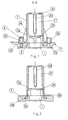
- Fig. 1
- den die Ablassöffnung des Bodenteils einer Ölwanne umgebenden Randbereich mit einem aufgesetzten Dom, als Längsschnitt,
- Fig. 2
- einen Schnitt gemäss der Linie A-A in Fig. 1,
- Fig. 3
- den am Boden einer Ölwanne befestigten Dom mit den eingesetzten Einzelteilen des Schraubverschlusses in der Stellung vor dem Eindrehen der Ablassschraube, als Längsschnitt,
- Fig. 4
- die Einzelteile des Schraubverschlusses als Explosionsdarstellung und
- Fig. 5
- den Schraubverschluss nach dem Eindrehen der Ablassschraube in der Verschlussstellung, als Längsschnitt.
Der Dom 3 weist einen nach leicht konisch verlaufenden Hohlraum zur Aufnahme der Einzelteile des Schraubverschlusses auf, der in einen oberen Abschnitt 3f und einen unteren Abschnitt 3h geringerer Bauhöhe unterteilt ist. An der Innenseite der den oberen Abschnitt 3f begrenzenden Wandung befinden sich vier in gleichem radialen Abstand angeordnete vertikal verlaufende Stege bzw. Nasen 3d, die als Führungselemente für den Klauenring 9 des Schraubverschlusses dienen. Am oberen Ende des unteren Abschnittes 3h ist an der Innenwandung eine umlaufende, zylindrische Nut 3g zur Aufnahme des einzusetzenden Sicherungsringes 6 angeordnet. Außerdem befinden sich in dem unteren Abschnitt 3h des Domes 3, im Bereich zwischen den Befestigungsstellen 3b, vier am Außenumfang verteilte Öffnungen 3e, durch die im Bedarfsfall das Öl vollständig ablaufen kann, da sich die Öffnungen 3e in Höhe des ebenen Bodenabschnitts der Ölwanne befinden.
Der aus Kunststoff hergestellte Dom 3 ist lediglich aus entformungstechnischen Gründen innen und außen leicht konisch ausgebildet. Der Dom kann auch als zylinderförmiges Bauteil ausgebildet sein.
Die Einzelzeile des in den Dom 3 einsetzbaren Verschlusses bestehen aus einer Schraubenfeder 10, deren oberes Ende an der Innenseite des Kopfteils 3c des Domes 3 anliegt, einem Klauenring 9, einem Wellring 8, einer Nuss bzw. Schraubelement 7 und dem Sicherungsring 6. Schraubenfeder 10, Klauenring 9, Wellring 8 und Nuss 7 werden durch den in die Ringnut 3g eingesetzten Sicherungsring 6 in dem oberen, Abschnitt 3f gehalten. Ein zu weites Einbringen der Ablassschraube 5 in axialer Richtung in den Abschnitt 3f wird dahingehend verhindert, dass die Nuss 7 sich mit dem Flansch 7a gegen die Unterseite der Nasen 3d abstützt (axiales Spiel der Nuss 7 ca. 1 mm).
Die Ablassschraube 5 wird mit ihrem oberen Gewindeabschnitt 5d in das Innengewinde der Nuss 7 eingeschraubt und besitzt einen unteren zylinderförmigen Flansch 5a, dessen Außendurchmesser dem Innendurchmesser der Ablassöffnung 1 unter Berücksichtigung des erforderlichen Spiels entspricht. In den Flansch 5a ist eine umlaufende Ringnut 5b zur Aufnahme eines elastomeren Dichtringes 11 eingearbeitet. An den Flansch 5a schließt sich in Achsrichtung nach oben ein zylinderförmiger Schaft 5c an, dessen Außendurchmesser kleiner ist als der Außendurchmesser des Flansches 5a. Oberhalb des Schaftes 5c ist der Gewindeabschnitt 5d der Schraube 5 angeordnet, der in seinem Außendurchmesser kleiner als der Schaft 5c ist. In den Flansch 5a ist noch eine Aufnahme 5e für einen Steckschlüssel eingearbeitet. Der Sicherungsring 6 ist in der Ringnut 3g, die sich im unteren Abschnitt 3h des Domes 3 befindet, eingesetzt. Auf dem Sicherungsring 6 liegt die Nuss 7 auf, die aus einer ringförmigen Scheibe 7a mit einer aufgesetzten Sechskantmutter 7b besteht. Die Nuss 7 wird in den Abschnitt 3f des Domes 3 eingesetzt und ist in der Einbaulage drehbar und durch den Sicherungsring 6 in dem Dom 3 gehalten. Ein weiteres Einschieben der Nuss 7 ist nicht möglich, da diese gegen die Nasen bzw. Stege 3d anschlägt. Der Wellring 8 besteht aus einem unteren ringförmigen Teil 8a, dessen Außendurchmesser kleiner als der Außendurchmesser des Flansches 7a der Nuss 7 ist, und einem oberen nahezu zylinderförmigen Schaft 8b mit einem wesentlich kleineren Außendurchmesser. Aufgrund der leicht konischen Ausführung des Innenraumes des Domes 3 besitzen der Schaft 8b und das untere Teil 8a ebenfalls eine leicht konisch verlaufende Mantelfläche, um einen passgenauen Sitz in Einbaulage zu gewährleisten. Das untere annähernd ringförmige Teil 8a, besitzt eine der Außenkontur der Mutter 7b angepasste sechskantförmige Ausnehmung zur Aufnahme der Sechskantmutter 7b, so dass in der Einbaulage die Nuss 7 und der Wellring 8 formschlüssig miteinander verbunden sind. Der Wellring 8 ist ebenfalls wie die Nuss 7, drehbar in dem Dom 3 gelagert. Die nach oben zeigende Stirnfläche des unteren Teils 8a des Wellringes 8 ist mit einer umlaufenden Verzahnung versehen, wobei eine Zahnflanke 8e der Zähne 8c gerade und die gegenüberliegende Zahnflanke 8d als schiefe Ebene ausgebildet ist. Die einzelnen Zähne 8c besitzen eine gerade verlaufende obere Stirnfläche. Der nachfolgende Klauenring 9 ist auf das obere Teil 8b des Wellringes 8 aufgesetzt und besitzt an seiner Unterseite eine mit der Verzahnung des Klauenringes 8 korrespondierende Verzahnung 9a, die in die Verzahnung des Wellringes 8 eingreifbar ist. Zwischen den beiden Verzahnungen von Wellring 8 und Klauenring 9 besteht ein radiales Spiel. Durch ein gegenläufiges Auflaufen der als schiefe Ebene ausgebildeten Zahnflanken von Wellring 8 und Klauenring 9 wird ein sogenanntes Überschnappen der Verzahnungen bewirkt. Der Wellring 8 und der Klauenring 9, die ineinander verschachtelt angeordnet sind, sind im Dom 3 axial beweglich gelagert. Am Außenumfang des Klauenringes 9 sind Nuten 9b eingearbeitet, die in die an der Innenwandung des Domes 3 befindlichen Stege bzw. Nasen 3d eingreifen, so dass der Klauenring 9 gegen Verdrehen gesichert ist. Der Klauenring 9 besitzt an seiner Oberseite noch einen radial zurückgesetzten Ringbund 9c, der als Aufnahme für die Druckfeder 10 dient. Die Nuss 7, der Wellring 8 und der Klauenring 9 werden in Einbaulage durch die Vorspannung der Druckfeder 10 gegen den Sicherungsring 6 gedrückt.
Die Funktionsweise des Schraubverschlusse ist folgende.
Nach dem Einbau der Bauteile Druckfeder 10, Klauenring 9, Wellring 8, Nuss 7 und Sicherungsring 6 in den Dom, wie in Fig. 3 gezeigt, wird die Schraube 5 mit dem eingelegten 0-Ring 11 in das Innengewinde der Mutter 7b der Nuss 7 eingedreht. Aufgrund der unter Vorspannung durch die Druckfeder 10 in dem Dom 3 gehaltenen Bauteile Klauenring 9, Wellring 8 und Nuss 7 wird beim Einschrauben der Schraube 5 ein Mitdrehen der Nuss 7 verhindert. Beim Einschrauben stößt die Schraube 5 zuerst mit ihrer oberen Stirnfläche gegen die Unterseite des Wellringes 8. Durch weiteres Eindrehen der Schraube 5 wird der Wellring 8 zusammen mit dem Klauenring 9 angehoben, wie in Fig. 5 zu sehen ist. Durch die axial auf die Schraube 5 wirkende Kraft der Druckfeder wird eine Selbstsicherung der Schraube 5 bewirkt. Durch eine Profilierung der Kontaktflächen Schraube/Nuss kann die Wirkung der Selbstsicherung noch erhöht werden. Hierzu sind z. B. an der Unterseite des Wellringes 8 fünf punktförmige Noppen 8f angeordnet, die in korrespondierende Ausnehmungen 5f an der oberen Stirnseite der Schraube 5 eingreifen.
Während des Einschraubvorganges wird der in der Ringnut 5b befindliche Dichtungsring 11 verformt und dabei gegen die Innenwandung der Ablassöffnung 1 gedrückt und somit die erforderliche Dichtheit hergestellt. Beim weiteren Eindrehen der Schraube 5 gelangt die obere Stirnseite des Schaftes 5c in Berührungskontakt mit der Nuss 7. Bei Erreichen dieses Anschlages ist die gewünschte Endstellung der Schraube 5 erreicht. Durch ein nunmehr unerwünschtes Weiterdrehen der Schraube 5 - ein sogenanntes Überdrehen - werden Nuss 7 und Wellring 8 mitgedreht. Dabei drücken diese den nicht versdrehbaren Klauenring 9 gegen die Druckfeder 10, wobei die Verzahnung zwischen dem Wellring 8 und dem Klauenring 9 aufgrund der schrägen Zahnflanken der benachbarten Zähne von Wellring und Klauenring außer Eingriff gelangt. Durch ein gegenläufiges Auflaufen der Zähne über schiefe Ebenen wird ein sogenanntes Überschnappen der Verzahnung bewirkt und damit ein Überdrehen der Schraube 5 ausgeschlossen.
Beim Lösen der Schraube 5 in entgegengesetzter Richtung gelangen die geraden Zahnflanken von Wellring 8 und Klauenring 9 wieder in Eingriff und die Schraube kann problemlos gelöst werden. Zum Ablassen von Öl wird die Schraube 5 vollständig oder zumindest bis zur Freigabe der Auslassöffnung 1 herausgedreht. Da das die Auslassöffnung umgebende Bodenteil 2 der Ölwanne keinen nach innen gerichteten Rand oder Kragen aufweist und eben bzw. geringfügig zur Mittelachse geneigt ausgebildet ist, kann das in der Ölwanne befindliche Öl vollständig ablaufen.
Mit dem vorgeschlagenen Schraubverschluss ist ein unerwünschtes Überdrehen beim Einschrauben der Ölablassschraube 5 ausgeschlossen. Im fest angezogenen und vollständig abgedichteten Zustand der Auslassöffnung wird durch den von der Druckfeder 10 auf die Ablassschraube 5 ausgeübten Druck noch eine Selbstsicherung der Ablassschraube bewirkt, so dass ein unerwünschtes Lösen der Ablassschraube 5 nicht möglich ist.
Der Dom 3, die Ablassschraube 5, die Nuss 7, der Wellenring 8 und der Klauenring 9 können als spritzgegossene Kunststoffbauteile ausgebildet sein.
Claims (14)
- Schraubverschluss für einen Flüssigkeitsbehälter, insbesondere eine Ölwanne für Kraftfahrzeuge, unter Verwendung einer Ablassschraube und einem elastomeren Dichtungselement zum dichten Verschließen der in dem Behälter angeordneten Ablassöffnung, dadurch gekennzeichnet, dass die Ablassöffnung (1) halsförmig ausgebildet ist und um die Ablassöffnung (1) ein in den Behälter ragender Dom (3) angeordnet ist, wobei der Dom (3) mindestens eine seitliche Öffnung (3e) besitzt und in dem Dom (3) ein ein Innengewinde aufweisendes Schraubelement (7) drehbar gehalten ist, in das die Ablassschraube (5) eindrehbar ist, wobei die Ablassschraube (5) einen Dichtungsring (11) zur radialen Abdichtung der halsförmigen Ablassöffnung (1) aufweist, und das Schraubelement (7) mit einer in dem Dom (3) angeordneten unter Vorspannung einer Druckfeder (10) stehenden Überdrehschutzeinheit (8, 9) in Wirkverbindung steht, und die Überdrehschutzeinheit (8, 9) nach Erreichen der Endstellung der eingedrehten Ablassschraube (5) mit dieser in Berührungskontakt steht und ein weiteres Eindrehen der Ablassschraube (5) verhindert.
- Schraubverschluss nach Anspruch 1, dadurch gekennzeichnet, dass die Überdrehschutzeinheit aus einem Wellring (8) und einem auf diesem aufliegenden Klauenring (9) besteht, wobei der Wellring (8) axial verschiebbar und drehbar gelagert ist und formschlüssig mit dem Schraubelement (7) verbunden ist, und der Klauenring (9), an dem die Druckfeder (10) anliegt, axial verschiebbar und gegen Verdrehen gesichert ist, und die benachbarten Kontaktflächen von Wellring (8) und Klauenring (9) mit einer ineinander eingreifbaren Verzahnung (8c, 9a) ausgerüstet sind, wobei die Zähne (8c, 9a) eine gerade Zahnflanke (8e) und eine als schiefe Ebene ausgebildete Zahnflanke (8d) aufweisen, und durch ein gegenläufiges Auflaufen der als schiefe Ebene ausgebildeten Zahnflanken beim Eindrehen der Ablassschraube (5) nach Erreichen der Endstellung ein Überschnappen und Durchdrehen des Wellringes (8) erfolgt und beim Lösen der Ablassschraube (5) Wellring (8) und Klauenring (9) über die geraden Zahnflanken (8e) miteinander in Eingriff gelangen.
- Schraubverschluss nach einem der Ansprüche 1 oder 2, dadurch gekennzeichnet, dass zwischen den beiden in Eingriff stehenden Verzahnungen von Wellring (8) und Klauenring (9) ein radiales Spiel vorhanden ist.
- Schraubverschluss nach einem der Ansprüche 1 bis 3, dadurch gekennzeichnet, dass das Schraubelement (7) aus einer ringförmigen Scheibe (7a) mit einer aufgesetzten Schraubmutter (7b) besteht und in dem Unterteil (8a) des Wellringes (8) eine passgenaue Ausnehmung zur Aufnahme der Schraubmutter (7b) angeordnet ist.
- Schraubverschluss nach einem der Ansprüche 1 bis 4, dadurch gekennzeichnet, dass der Wellring (8) aus einem annähernd ringförmigen Unterteil (8a) und einem annähernd zylinderförmigen Schaft (8b) besteht und der Klauenring (9) mit seiner ringförmigen Ausnehmung auf den Schaft (8b) aufgesteckt ist.
- Schraubverschluss nach einem der Ansprüche 1 bis 5, dadurch gekennzeichnet, dass in dem Dom (3) ein Sicherungsring (6) zur Lagefixierung der unter Vorspannung der Druckfeder (10) stehenden Bauteile Klauenring (9), Wellring (8) und Schraubelement (7) eingesetzt ist.
- Schraubverschluss nach einem der Ansprüche 1 bis 6, dadurch gekennzeichnet, dass die Ablassschraube (5) einen unteren Flansch (5a), einen sich daran anschließenden Schaft (5c) und Gewindeabschnitt (5d) besitzt, wobei der Flansch (5a) sich über die gesamte Höhe der halsförmigen Ablassöffnung (1) erstreckt und eine umlaufende Ringnut (5b) zur Aufnahme des Dichtringes (11) aufweist, der Schaft (5c) radial zurückgesetzt ist und eine obere Stirnfläche besitzt, die beim Eindrehen der Ablassschraube (5) in die Schraubmutter (7b) mit der ringförmigen Scheibe (7a) des Schraubelementes (7) in Berührungskontakt gelangt.
- Schraubverschluss nach einem der Ansprüche 1 bis 7, dadurch gekennzeichnet, dass an der Unterseite des Wellringes (8) Profilierungen (8f) angeordnet sind, die in entsprechende Ausnehmungen (5f) an der oberen Stirnseite des Gewindeabschnittes (5d) der Ablassschraube (5) eingreifen oder umgekehrt.
- Schraubverschluss nach einem der Ansprüche 1 bis 8, dadurch gekennzeichnet, dass der Dom (3) mehrere Befestigungsstellen (3b) zu seiner Befestigung mittels selbstschneidender Kunststoffschrauben (4) an dem Boden- oder Wandteil (2) besitzt.
- Schraubverschluss nach einem der Ansprüche 1 bis 9, dadurch gekennzeichnet, dass der Dom (3) an seinem in Wand- oder Bodenrichtung zeigenden Ende mehrere seitlich vorstehende Flanschabschnitte (3a) besitzt, die in im Boden- oder Wandteil (2) angeordnete Führungen (2a) eingesetzt sind.
- Schraubverschluss nach einem der Ansprüche 1 bis 10, dadurch gekennzeichnet, dass der Innenraum des Domes (3) leicht konisch ausgebildet ist und in einen oberen Abschnitt (3f) und einen unteren Abschnitt (3h) unterteilt ist , wobei in dem oberen Abschnitt (3f) an der Innenseite mehrere vertikal verlaufende Führungselemente (3d) zur Sicherung des Klauenringes (9) gegen Verdrehen angeordnet sind und in dem unteren Abschnitt (3h) eine Ringnut (3g) zur Aufnahme des Sicherungsringes (6) eingearbeitet ist.
- Schraubverschluss nach einem der Ansprüche 1 bis 11, dadurch gekennzeichnet, dass der Dom (3) in seinem unteren Abschnitt (3h), im Bereich zwischen den Befestigungsstellen (3b), eine oder mehrere am Außenumfang verteilte Öffnungen (3e) besitzt.
- Schraubverschluss nach einem der Ansprüche 1 bis 12, dadurch gekennzeichnet, dass die halsförmige Ablassöffnung (1) als ringförmiger, nach unten abstehender Bund ausgebildet ist und der an die Ablassöffnung (1) angrenzende Bodenabschnitt (2) des Behälters eben ausgebildet ist und die Öffnungen (3e) des Domes (3) sich in Höhe des Bodenabschnittes (2) befinden.
- Schraubverschluss nach einem der Ansprüche 1 bis 13, dadurch gekennzeichnet, dass eines oder mehrere der Bauteile Dom (3), Nuss (7), Ablassschraube (5), Klauenring (9) und Wellring (8) als spritzgegossenes Kunststoffbauteil ausgebildet sind.
Applications Claiming Priority (2)
| Application Number | Priority Date | Filing Date | Title |
|---|---|---|---|
| DE20120432U DE20120432U1 (de) | 2001-12-18 | 2001-12-18 | Schraubverschluss für Flüssigkeitsbehälter, insbesondere einer Ölwanne für Kraftfahrzeuge |
| DE20120432U | 2001-12-18 |
Publications (2)
| Publication Number | Publication Date |
|---|---|
| EP1321636A1 true EP1321636A1 (de) | 2003-06-25 |
| EP1321636B1 EP1321636B1 (de) | 2007-01-24 |
Family
ID=7965287
Family Applications (1)
| Application Number | Title | Priority Date | Filing Date |
|---|---|---|---|
| EP02028291A Expired - Lifetime EP1321636B1 (de) | 2001-12-18 | 2002-12-17 | Schraubverschluss für Flüssigkeitsbehälter, insbesondere einer Ölwanne für Kraftfahrzeuge |
Country Status (4)
| Country | Link |
|---|---|
| EP (1) | EP1321636B1 (de) |
| AT (1) | ATE352705T1 (de) |
| DE (2) | DE20120432U1 (de) |
| ES (1) | ES2280479T3 (de) |
Cited By (3)
| Publication number | Priority date | Publication date | Assignee | Title |
|---|---|---|---|---|
| DE102007030529A1 (de) | 2007-06-30 | 2009-01-08 | Daimler Ag | Verschlussanordnung |
| DE102008057518A1 (de) | 2008-11-15 | 2010-05-20 | Daimler Ag | Verschlusseinrichtung |
| CN114215645A (zh) * | 2021-11-29 | 2022-03-22 | 中国航发沈阳发动机研究所 | 一种航空发动机放油磁塞体结构 |
Families Citing this family (4)
| Publication number | Priority date | Publication date | Assignee | Title |
|---|---|---|---|---|
| DE102004060054B4 (de) * | 2004-12-14 | 2016-03-17 | Zf Friedrichshafen Ag | Vorrichtung zum Ablassen des in einem oder mehreren Bauteilen des Antriebsstrangs eines Kraftfahrzeugs enthaltenen Öls |
| DE102008014688B4 (de) | 2008-03-18 | 2013-02-21 | Rehau Ag + Co. | Ölwanne sowie Verschlusselement für eine Ölwanne |
| DE102008001137A1 (de) * | 2008-04-14 | 2009-10-15 | Zf Friedrichshafen Ag | Anordnung mit zumindest einem Aufnahmebehältnis für ein Fluid an einem Bodenbereich eines Fahrzeuges |
| DE102009019189A1 (de) * | 2009-04-28 | 2010-11-04 | Volkswagen Ag | Verschluss-Schraubverbindung, Zahnstangenlenkung und Verfahren zum Einstellen eines Druckstücks einer Zahnstangenlenkung |
Citations (3)
| Publication number | Priority date | Publication date | Assignee | Title |
|---|---|---|---|---|
| US3879013A (en) * | 1972-10-27 | 1975-04-22 | Caterpillar Tractor Co | Check-type drain valve |
| US4205758A (en) * | 1979-04-10 | 1980-06-03 | Johnson Harley D | Replacement oil pan plug |
| DE4232893A1 (de) | 1991-09-30 | 1993-04-01 | Skf Usa Inc | Ablassschraube |
-
2001
- 2001-12-18 DE DE20120432U patent/DE20120432U1/de not_active Expired - Lifetime
-
2002
- 2002-12-17 DE DE50209336T patent/DE50209336D1/de not_active Expired - Lifetime
- 2002-12-17 ES ES02028291T patent/ES2280479T3/es not_active Expired - Lifetime
- 2002-12-17 AT AT02028291T patent/ATE352705T1/de not_active IP Right Cessation
- 2002-12-17 EP EP02028291A patent/EP1321636B1/de not_active Expired - Lifetime
Patent Citations (3)
| Publication number | Priority date | Publication date | Assignee | Title |
|---|---|---|---|---|
| US3879013A (en) * | 1972-10-27 | 1975-04-22 | Caterpillar Tractor Co | Check-type drain valve |
| US4205758A (en) * | 1979-04-10 | 1980-06-03 | Johnson Harley D | Replacement oil pan plug |
| DE4232893A1 (de) | 1991-09-30 | 1993-04-01 | Skf Usa Inc | Ablassschraube |
Cited By (4)
| Publication number | Priority date | Publication date | Assignee | Title |
|---|---|---|---|---|
| DE102007030529A1 (de) | 2007-06-30 | 2009-01-08 | Daimler Ag | Verschlussanordnung |
| DE102008057518A1 (de) | 2008-11-15 | 2010-05-20 | Daimler Ag | Verschlusseinrichtung |
| CN114215645A (zh) * | 2021-11-29 | 2022-03-22 | 中国航发沈阳发动机研究所 | 一种航空发动机放油磁塞体结构 |
| CN114215645B (zh) * | 2021-11-29 | 2023-04-18 | 中国航发沈阳发动机研究所 | 一种航空发动机放油磁塞体结构 |
Also Published As
| Publication number | Publication date |
|---|---|
| ES2280479T3 (es) | 2007-09-16 |
| DE50209336D1 (de) | 2007-03-15 |
| ATE352705T1 (de) | 2007-02-15 |
| EP1321636B1 (de) | 2007-01-24 |
| DE20120432U1 (de) | 2002-03-14 |
Similar Documents
| Publication | Publication Date | Title |
|---|---|---|
| EP1961976B1 (de) | Befestigungseinheit | |
| EP1437560B1 (de) | Kondensator mit Sammelbehälter und Schutzkappe | |
| DE69916063T2 (de) | Entfernbare schraubstopfen und werkzeug | |
| DE202007008152U1 (de) | Befestigungseinrichtung mit Toleranzausgleich | |
| DE102006004678B4 (de) | Montageeinheit für die Befestigungsöse eines Gurtschlosses | |
| EP1296069B1 (de) | Abgedichtete, verstellbare und selbsthemmende Schraubverbindung | |
| EP2157324A2 (de) | Schraube mit Dichtscheibenanordnung | |
| EP2444604A1 (de) | Aufnahmebehältnis für ein Fluid, insbesondere Motorölwanne oder Getriebeölwanne für ein KFZ | |
| WO2021140027A1 (de) | Verbindungselement und verbindungsanordnung | |
| DE10133063B4 (de) | Befestigungsvorrichtung und Befestigungselement | |
| EP1321636B1 (de) | Schraubverschluss für Flüssigkeitsbehälter, insbesondere einer Ölwanne für Kraftfahrzeuge | |
| DE10236649A1 (de) | Druckfühler für einen Reifen | |
| EP0759377B1 (de) | Anordnung zur Einstellung des Reflektorneigungenswinkels bei Frontscheinwerfeern eines Kraftfahrzeuges | |
| DE20213362U1 (de) | Befestigungsanordnung für eine Heckleuchte | |
| EP3742009B1 (de) | Befestigungsvorrichtung für toilettenabdeckungen | |
| DE29903686U1 (de) | Schraube | |
| EP0271648A1 (de) | System zum Befestigen von Fassadenplatten an einer Unterkonstruktion | |
| DE19528621C1 (de) | Vorrichtung zum Verschließen von Bohrungen | |
| DE10214378C1 (de) | Schraubverbindung mit Toleranzausgleich | |
| DE19947388B4 (de) | Behältnis zur Aufnahme eines Füllgutes mit einem Drehverschluss | |
| DE19803261C1 (de) | Toleranzausgleichsvorrichtung | |
| DE102021123179B4 (de) | Verwendung einer Anbauteil-Außenkonusabdeckkappe, Anbauteil-Abdeckkappenbaugruppe, Anbauteilbaugruppe, Set und Verfahren | |
| EP1517098B1 (de) | Heizkörperventil | |
| DE4435165B4 (de) | Verschlußdeckel für einen Betriebsstoffbehälter | |
| DE3232178A1 (de) | Verschlussdeckel |
Legal Events
| Date | Code | Title | Description |
|---|---|---|---|
| PUAI | Public reference made under article 153(3) epc to a published international application that has entered the european phase |
Free format text: ORIGINAL CODE: 0009012 |
|
| 17P | Request for examination filed |
Effective date: 20030423 |
|
| AK | Designated contracting states |
Designated state(s): AT BE BG CH CY CZ DE DK EE ES FI FR GB GR IE IT LI LU MC NL PT SE SI SK TR |
|
| AX | Request for extension of the european patent |
Extension state: AL LT LV MK RO |
|
| AKX | Designation fees paid |
Designated state(s): AT BE BG CH CY CZ DE DK EE ES FI FR GB GR IE IT LI LU MC NL PT SE SI SK TR |
|
| RAP1 | Party data changed (applicant data changed or rights of an application transferred) |
Owner name: KTSN KUNSTSTOFFTECHNIK SACHSEN GMBH & CO. KG |
|
| GRAP | Despatch of communication of intention to grant a patent |
Free format text: ORIGINAL CODE: EPIDOSNIGR1 |
|
| GRAS | Grant fee paid |
Free format text: ORIGINAL CODE: EPIDOSNIGR3 |
|
| GRAA | (expected) grant |
Free format text: ORIGINAL CODE: 0009210 |
|
| AK | Designated contracting states |
Kind code of ref document: B1 Designated state(s): AT BE BG CH CY CZ DE DK EE ES FI FR GB GR IE IT LI LU MC NL PT SE SI SK TR |
|
| PG25 | Lapsed in a contracting state [announced via postgrant information from national office to epo] |
Ref country code: SI Free format text: LAPSE BECAUSE OF FAILURE TO SUBMIT A TRANSLATION OF THE DESCRIPTION OR TO PAY THE FEE WITHIN THE PRESCRIBED TIME-LIMIT Effective date: 20070124 Ref country code: IE Free format text: LAPSE BECAUSE OF FAILURE TO SUBMIT A TRANSLATION OF THE DESCRIPTION OR TO PAY THE FEE WITHIN THE PRESCRIBED TIME-LIMIT Effective date: 20070124 Ref country code: FI Free format text: LAPSE BECAUSE OF FAILURE TO SUBMIT A TRANSLATION OF THE DESCRIPTION OR TO PAY THE FEE WITHIN THE PRESCRIBED TIME-LIMIT Effective date: 20070124 Ref country code: DK Free format text: LAPSE BECAUSE OF FAILURE TO SUBMIT A TRANSLATION OF THE DESCRIPTION OR TO PAY THE FEE WITHIN THE PRESCRIBED TIME-LIMIT Effective date: 20070124 |
|
| REG | Reference to a national code |
Ref country code: GB Ref legal event code: FG4D Free format text: NOT ENGLISH |
|
| REG | Reference to a national code |
Ref country code: CH Ref legal event code: EP |
|
| REG | Reference to a national code |
Ref country code: IE Ref legal event code: FG4D Free format text: LANGUAGE OF EP DOCUMENT: GERMAN |
|
| REF | Corresponds to: |
Ref document number: 50209336 Country of ref document: DE Date of ref document: 20070315 Kind code of ref document: P |
|
| PG25 | Lapsed in a contracting state [announced via postgrant information from national office to epo] |
Ref country code: BG Free format text: LAPSE BECAUSE OF THE APPLICANT RENOUNCES Effective date: 20070425 |
|
| REG | Reference to a national code |
Ref country code: SE Ref legal event code: TRGR |
|
| GBT | Gb: translation of ep patent filed (gb section 77(6)(a)/1977) |
Effective date: 20070419 |
|
| PG25 | Lapsed in a contracting state [announced via postgrant information from national office to epo] |
Ref country code: PT Free format text: LAPSE BECAUSE OF FAILURE TO SUBMIT A TRANSLATION OF THE DESCRIPTION OR TO PAY THE FEE WITHIN THE PRESCRIBED TIME-LIMIT Effective date: 20070625 |
|
| ET | Fr: translation filed | ||
| REG | Reference to a national code |
Ref country code: IE Ref legal event code: FD4D |
|
| REG | Reference to a national code |
Ref country code: ES Ref legal event code: FG2A Ref document number: 2280479 Country of ref document: ES Kind code of ref document: T3 |
|
| PG25 | Lapsed in a contracting state [announced via postgrant information from national office to epo] |
Ref country code: SK Free format text: LAPSE BECAUSE OF FAILURE TO SUBMIT A TRANSLATION OF THE DESCRIPTION OR TO PAY THE FEE WITHIN THE PRESCRIBED TIME-LIMIT Effective date: 20070124 |
|
| PLBE | No opposition filed within time limit |
Free format text: ORIGINAL CODE: 0009261 |
|
| STAA | Information on the status of an ep patent application or granted ep patent |
Free format text: STATUS: NO OPPOSITION FILED WITHIN TIME LIMIT |
|
| 26N | No opposition filed |
Effective date: 20071025 |
|
| PG25 | Lapsed in a contracting state [announced via postgrant information from national office to epo] |
Ref country code: GR Free format text: LAPSE BECAUSE OF FAILURE TO SUBMIT A TRANSLATION OF THE DESCRIPTION OR TO PAY THE FEE WITHIN THE PRESCRIBED TIME-LIMIT Effective date: 20070425 Ref country code: IT Free format text: LAPSE BECAUSE OF NON-PAYMENT OF DUE FEES Effective date: 20071217 |
|
| BERE | Be: lapsed |
Owner name: KTSN KUNSTSTOFFTECHNIK SACHSEN G.M.B.H. & CO. KG Effective date: 20071231 |
|
| PG25 | Lapsed in a contracting state [announced via postgrant information from national office to epo] |
Ref country code: MC Free format text: LAPSE BECAUSE OF NON-PAYMENT OF DUE FEES Effective date: 20071231 |
|
| REG | Reference to a national code |
Ref country code: CH Ref legal event code: PL |
|
| EUG | Se: european patent has lapsed | ||
| GBPC | Gb: european patent ceased through non-payment of renewal fee |
Effective date: 20071217 |
|
| NLV4 | Nl: lapsed or anulled due to non-payment of the annual fee |
Effective date: 20080701 |
|
| PG25 | Lapsed in a contracting state [announced via postgrant information from national office to epo] |
Ref country code: BE Free format text: LAPSE BECAUSE OF NON-PAYMENT OF DUE FEES Effective date: 20071231 |
|
| PG25 | Lapsed in a contracting state [announced via postgrant information from national office to epo] |
Ref country code: SE Free format text: LAPSE BECAUSE OF NON-PAYMENT OF DUE FEES Effective date: 20071218 Ref country code: LI Free format text: LAPSE BECAUSE OF NON-PAYMENT OF DUE FEES Effective date: 20071231 Ref country code: CZ Free format text: LAPSE BECAUSE OF NON-PAYMENT OF DUE FEES Effective date: 20071217 Ref country code: CH Free format text: LAPSE BECAUSE OF NON-PAYMENT OF DUE FEES Effective date: 20071231 |
|
| REG | Reference to a national code |
Ref country code: FR Ref legal event code: ST Effective date: 20081020 |
|
| PG25 | Lapsed in a contracting state [announced via postgrant information from national office to epo] |
Ref country code: NL Free format text: LAPSE BECAUSE OF NON-PAYMENT OF DUE FEES Effective date: 20080701 |
|
| PG25 | Lapsed in a contracting state [announced via postgrant information from national office to epo] |
Ref country code: GB Free format text: LAPSE BECAUSE OF NON-PAYMENT OF DUE FEES Effective date: 20071217 |
|
| PG25 | Lapsed in a contracting state [announced via postgrant information from national office to epo] |
Ref country code: EE Free format text: LAPSE BECAUSE OF FAILURE TO SUBMIT A TRANSLATION OF THE DESCRIPTION OR TO PAY THE FEE WITHIN THE PRESCRIBED TIME-LIMIT Effective date: 20070124 |
|
| REG | Reference to a national code |
Ref country code: ES Ref legal event code: FD2A Effective date: 20071218 |
|
| PG25 | Lapsed in a contracting state [announced via postgrant information from national office to epo] |
Ref country code: AT Free format text: LAPSE BECAUSE OF NON-PAYMENT OF DUE FEES Effective date: 20071217 Ref country code: ES Free format text: LAPSE BECAUSE OF NON-PAYMENT OF DUE FEES Effective date: 20071218 Ref country code: FR Free format text: LAPSE BECAUSE OF NON-PAYMENT OF DUE FEES Effective date: 20071231 |
|
| PG25 | Lapsed in a contracting state [announced via postgrant information from national office to epo] |
Ref country code: CY Free format text: LAPSE BECAUSE OF FAILURE TO SUBMIT A TRANSLATION OF THE DESCRIPTION OR TO PAY THE FEE WITHIN THE PRESCRIBED TIME-LIMIT Effective date: 20070124 |
|
| PG25 | Lapsed in a contracting state [announced via postgrant information from national office to epo] |
Ref country code: LU Free format text: LAPSE BECAUSE OF NON-PAYMENT OF DUE FEES Effective date: 20071217 |
|
| PG25 | Lapsed in a contracting state [announced via postgrant information from national office to epo] |
Ref country code: TR Free format text: LAPSE BECAUSE OF FAILURE TO SUBMIT A TRANSLATION OF THE DESCRIPTION OR TO PAY THE FEE WITHIN THE PRESCRIBED TIME-LIMIT Effective date: 20070124 |
|
| REG | Reference to a national code |
Ref country code: DE Ref legal event code: R082 Ref document number: 50209336 Country of ref document: DE Representative=s name: WEIDNER STERN JESCHKE PATENTANWAELTE PARTNERSC, DE |
|
| PGFP | Annual fee paid to national office [announced via postgrant information from national office to epo] |
Ref country code: DE Payment date: 20200817 Year of fee payment: 19 |
|
| REG | Reference to a national code |
Ref country code: DE Ref legal event code: R082 Ref document number: 50209336 Country of ref document: DE Representative=s name: WEIDNER STERN JESCHKE PATENTANWAELTE PARTNERSC, DE Ref country code: DE Ref legal event code: R081 Ref document number: 50209336 Country of ref document: DE Owner name: EISSMANN AUTOMOTIVE KTSN GMBH, DE Free format text: FORMER OWNER: KTSN KUNSTSTOFFTECHNIK SACHSEN GMBH & CO. KG, 01796 PIRNA, DE |
|
| REG | Reference to a national code |
Ref country code: DE Ref legal event code: R081 Ref document number: 50209336 Country of ref document: DE Owner name: EISSMANN AUTOMOTIVE KTSN GMBH, DE Free format text: FORMER OWNER: MINDA KTSN PLASTIC SOLUTIONS GMBH & CO. KG, 01796 PIRNA, DE Ref country code: DE Ref legal event code: R082 Ref document number: 50209336 Country of ref document: DE Representative=s name: WEIDNER STERN JESCHKE PATENTANWAELTE PARTNERSC, DE |
|
| REG | Reference to a national code |
Ref country code: DE Ref legal event code: R082 Ref document number: 50209336 Country of ref document: DE Representative=s name: BARDEHLE PAGENBERG PARTNERSCHAFT MBB PATENTANW, DE |
|
| REG | Reference to a national code |
Ref country code: DE Ref legal event code: R119 Ref document number: 50209336 Country of ref document: DE |
|
| PG25 | Lapsed in a contracting state [announced via postgrant information from national office to epo] |
Ref country code: DE Free format text: LAPSE BECAUSE OF NON-PAYMENT OF DUE FEES Effective date: 20220701 |