EP1321378A1 - Klemmvorrichtung und Verfahren zum Halten und Transportieren von Materialien - Google Patents
Klemmvorrichtung und Verfahren zum Halten und Transportieren von Materialien Download PDFInfo
- Publication number
- EP1321378A1 EP1321378A1 EP02027735A EP02027735A EP1321378A1 EP 1321378 A1 EP1321378 A1 EP 1321378A1 EP 02027735 A EP02027735 A EP 02027735A EP 02027735 A EP02027735 A EP 02027735A EP 1321378 A1 EP1321378 A1 EP 1321378A1
- Authority
- EP
- European Patent Office
- Prior art keywords
- clamping device
- staple
- arm
- clamp
- bracket arm
- Prior art date
- Legal status (The legal status is an assumption and is not a legal conclusion. Google has not performed a legal analysis and makes no representation as to the accuracy of the status listed.)
- Granted
Links
Images



Classifications
-
- B—PERFORMING OPERATIONS; TRANSPORTING
- B65—CONVEYING; PACKING; STORING; HANDLING THIN OR FILAMENTARY MATERIAL
- B65B—MACHINES, APPARATUS OR DEVICES FOR, OR METHODS OF, PACKAGING ARTICLES OR MATERIALS; UNPACKING
- B65B17/00—Other machines, apparatus, or methods for packaging articles or materials
- B65B17/02—Joining articles, e.g. cans, directly to each other for convenience of storage, transport, or handling
-
- B—PERFORMING OPERATIONS; TRANSPORTING
- B65—CONVEYING; PACKING; STORING; HANDLING THIN OR FILAMENTARY MATERIAL
- B65D—CONTAINERS FOR STORAGE OR TRANSPORT OF ARTICLES OR MATERIALS, e.g. BAGS, BARRELS, BOTTLES, BOXES, CANS, CARTONS, CRATES, DRUMS, JARS, TANKS, HOPPERS, FORWARDING CONTAINERS; ACCESSORIES, CLOSURES, OR FITTINGS THEREFOR; PACKAGING ELEMENTS; PACKAGES
- B65D67/00—Kinds or types of packaging elements not otherwise provided for
- B65D67/02—Clips or clamps for holding articles together for convenience of storage or transport
Definitions
- the invention relates to a clamping device for holding together and transporting materials as well Process for holding and transporting materials.
- brackets for Binding sheets of paper or other materials together brackets and a. also in technical work processes used. For example, parentheses become also required for the disposal of fuel elements. When disposing of fuel assemblies, the fuel assemblies become sawed under water and the resulting Pieces are grouped together with the help of a bracket to be able to transport for further process steps. The brackets often serve as holders to hold the Transport fuel elements.
- brackets are designed so that Staple material is clamped between two clamp arms and is held together by the pressure of the clamp arms.
- the clamp is used as Transport aid used. It can be caused by the train movements on the clamp, to bend open the clamp arms come so that the staple comes out of the staple loosens and falls out. This can become security relevant Problems of disposal and transportation more dangerous Lead goods.
- the invention Clamping device has a clamp arm that with both its inside and outside Exerts pressure on the staple, d. H. from both sides is surrounded by the staple, so that bending of the clamping device is prevented.
- Figure 1 shows a side view of the clamping device (1) with the longer bracket arm (2) and the shorter one Clamp arm (3), which has a bulge (4).
- On the head side (5) of the clamping device (1) is one Marking mark (6) attached.
- the lower end (7) of the bracket arm (2) is bent vertically upwards and has an additional bend (8).
- the one through the Arrows and the letter "t" marked area defined the depth of the clamping device (1) and thus the Thickness of the staple, which is caused by the clamping device (1) can be fixed.
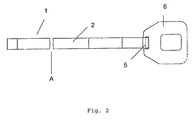
- Fig. 2 shows a plan view of the clamping device (1).
- the clamping device (1) is on the head side (5) provided with a marker (6).
- an interruption (A) is drawn to the to illustrate variable length of the clamping device (1).
- Figure 3 shows a side view of the clamping device (1) with clamped material (9).
- the bracket arms (2/3) can match both the area of the insides their bracket arms (2/3) as well as the area of the Outside of the shorter bracket arm (3), in particular through the bulge (4), pressure on the staple (9) exercise.
- the staple (9) At the lower end (7) of the longer bracket arm (2) the staple (9) by bending the lower End (7) of the clamp arm (2) held together.
- Figure 3 was in the drawing of the Device shows an interruption (A) to to illustrate the variable length of the clamping device (1).
- Figure 4 shows a plan view of the clamping device (1) with staple material (9) from the direction of the head side (5).
- the marking mark (6) on the Head side (5) of the clamping device (1) is attached, recognizable in supervision.
- the bulge (4) of the The clamp arm (3) can also be seen from above.
- Figure 5 shows a top view of the stapler (10) with the clamped clamping device (1).
- the longer clamp arm (2) of the clamping device (1) is in the same supervision as seen in Figure 2.
- the stapler (10) is provided with a bending arm (11).
- Figures 6a and 6b show the lower section of the stapler (10) with the lower end (7) of the bracket arm (2) and the clamped staple (9) in the Side view.
- the bending arm (11) connects precisely the lower end (7) and the bend (8) of the bracket arm (2).
- Figure 6b shows the folded arm (11) from its vertical position as in Figure 6a, folded down into a horizontal position is. In FIG. 6b, part of the lower end (7) the bracket arm (2) also from the vertical position, as in Figure 6a, in the horizontal position folded.
- the clamping device (1) is inserted into the automatic clamps (10).
- the staple (9), such as. B. the fuel tubes or other dangerous goods or materials are inserted and lowered in a slightly inclined position in the clamping device (1) in the direction of the head side (5).
- the staple (9) is now between the two clamp arms (2/3).
- the vertically upward bent end (7) of the clamp arm (2) is bent with the help of the bending arm (11) according to the thickness of the clamp material (9).
- the bend (8) of the lower end (7) facilitates the exact guidance of the bending arm (11) along the bracket arm (2).
- the clamp material (9) can additionally be fixed by this advantageous embodiment of the device, in which the lower side (7) of the clamping device (1) is bent according to the thickness of the clamp material.
- the staple can include spent tubular fuel assemblies that have been sawn under water and divided into 4 individual pipe sections by the sawing process, for example. These individual pieces can be held together with the clamping device (1) according to the invention and transported further.
- the staple (9) is clamped between the longer bracket arm (2) and the shorter bracket arm (3).
- the shorter clamp arm (3) exerts pressure on the clamp material (9) both with the area of its inside and with the area of its outside, in particular with the aid of its bulge (4). If tubular or rod-shaped staple material (9) is used, the shorter clamp arm (3) presses not only against the region of the staple material (9) which is located between the two clamp arms (2/3), but also against the region of the is outside the shorter bracket arm (3).
- the bulge (4) can be designed differently. For example, it can have an angular shape or be characterized by an oblique angling of the bracket arm (3). In a particularly preferred embodiment of the clamping device (1), the bulge has an arcuate shape (see FIG. 1). The bulge (4) can be designed or curved so strongly that it presses directly against the staple (9) after the staple (9) has been clamped.
- the bulge (4) can be designed such that after the staple (9) has been inserted into the clamping device between the outside of the staple arm (3) with the bulge (4) and the staple (9) outside the staple arms ( 2/3) there is still a free space, and only by the pulling movement on the head (5) of the clamping device (1) the clamp arm (3) is bent so that the bulge (4) presses against the clamp material (9).
- the size of the staple (9) or the number of fuel rods which is held together with the clamping device (1) depends on the length and depth t of the clamping device (1), which can be varied as desired. Usually, for each clamping device (1) z. B. 4 fuel rods held together.
- the thickness of the staple (9), ie for example the number of fuel elements that can be held together in this way, is predetermined by the depth t of the clamping device (1).
- the depth t of the clamping device (1) should correspond to the thickness d of the material to be clamped (9). For example, it can be 95 mm.
- the clamping device (1) can be raised on the head side (5) in order to transport the staple (9). Because the shorter clamp arm (3) is surrounded by the clamp material (9) both from the inside and from the outside, the clamping device (1) cannot bend open.
- the staple (9) z. B. the fuel can not fall out, so that safe transport with the help of the clamping device (1) is possible.
- the marking mark (6) on the head side (5) of the clamping device (1) facilitates the identification of the staple (9).
- the marking mark (6) can serve as a handle for a gripping arm of a lifting device.
- the clamping device according to the invention (1) can metal strips, especially aluminum strips with the dimensions 16 mm width, 1000 mm length and 1 mm Starch can be used.
- the shaping takes place over Segments.
- the aluminum strips are cut piece by piece into the desired shape using prefabricated forms pressed.
- the shorter bracket arm (3) with the bulge (4) can be done by welding two aluminum strips be reinforced.
- At the head (5) of the clamping device (1) can use a marker made of aluminum be used as a handle and to identify the staple can serve.
- the clamping device (1) is in an advantageous embodiment made of flat material designed to prevent damage to the clamping material (9) through sharp edges of the clamping device (1) or possibly drilling the clamping device into the Prevent jammed goods (9).
- the device becomes the clamping device (1) made of aluminum, because it is particularly cheap Corrosion properties are given and no chemical Reactions with the staple material used (9) occur.
Landscapes
- Engineering & Computer Science (AREA)
- Mechanical Engineering (AREA)
- Clamps And Clips (AREA)
- Load-Engaging Elements For Cranes (AREA)
- Portable Nailing Machines And Staplers (AREA)
- Folding Of Thin Sheet-Like Materials, Special Discharging Devices, And Others (AREA)
Abstract
Description
- Fig. 1:
- Seitenansicht Klemmvorrichtung
- Fig. 2:
- Aufsicht Klemmvorrichtung
- Fig. 3:
- Seitenansicht Klemmvorrichtung mit Klammergut
- Fig. 4:
- Aufsicht Klemmvorrichtung mit Klammergut
- Fig. 5:
- Aufsicht Klammerautomat mit Klemmvorrichtung
- Fig. 6a/6b:
- Seitenansicht Klemmvorrichtung mit Klammerautomat und Klammergut
Das senkrecht nach oben gebogene Ende (7) des Klammerarms (2) wird mit Hilfe des Biegearms (11) entsprechend der Dicke des Klammerguts (9) umgebogen. Die Biegung (8) des unteren Endes (7) erleichtert die exakte Führung des Biegearms (11) entlang des Klammerarms (2). Das Klammergut (9) kann durch diese vorteilhafte Ausgestaltung der Vorrichtung, bei der die untere Seite (7) der Klemmvorrichtung (1) entsprechend der Dicke des Klammerguts umgebogen wird, zusätzlich fixiert werden. Das Klammergut kann abgebrannte rohrförmige Brennelemente umfassen, die unter Wasser zersägt wurden und durch den Sägevorgang beispielsweise in 4 einzelne Rohrabschnitte geteilt wurden. Diese Einzelstücke können mit der erfindungsgemäßen Klemmvorrichtung (1) zusammengehalten und weiter transportiert werden. Das Klammergut (9) wird zwischen den längeren Klammerarm (2) und den kürzeren Klammerarm (3) eingeklemmt. Der kürzere Klammerarm (3) übt sowohl mit der Fläche seiner Innenseite als auch mit der Fläche seiner Außenseite, insbesondere mit Hilfe seiner Ausbuchtung (4), Druck auf das Klammergut (9) aus. Wenn röhren- oder stabförmiges Klammergut (9) eingesetzt wird, drückt der kürzere Klammerarm (3) nicht nur gegen den Bereich des Klammerguts (9), welcher sich zwischen den beiden Klammerarmen (2/3) befindet, sondern auch gegen den Bereich, der sich außerhalb des kürzeren Klammerarms (3) befindet. Diese Anordnung bewirkt, daß zum einen das Klammergut von zwei Seiten fixiert wird und zum anderen, daß ein Aufbiegen des kürzeren Klammerarms (3) verhindert wird.
Die Ausbuchtung (4) kann unterschiedlich ausgestaltet sein. Sie kann beispielsweise eine eckige Gestalt aufweisen oder durch eine schräge Abwinkelung des Klammerarms (3) gekennzeichnet sein. In einer besonders bevorzugten Ausführung der Klemmvorrichtung (1) weist die Ausbuchtung eine bogenförmige Gestalt auf (s. Fig.1). Die Ausbuchtung (4) kann so stark ausgebildet bzw. gewölbt sein, daß sie nach dem Einklemmen des Klammerguts (9) direkt gegen das Klammergut (9) drückt. In einer weiteren Ausführung kann die Ausbuchtung (4) so gestaltet sein, daß nach dem Einlegen des Klammerguts (9) in die Klemmvorrichtung zwischen der Außenseite des Klammerarms (3) mit der Ausbuchtung (4) und dem Klammergut (9) außerhalb der Klammerarme (2/3) noch ein Freiraum erhalten bleibt, und erst durch die Zugbewegung am Kopf (5) der Klemmvorrichtung (1) der Klammerarm (3) so gebogen wird, daß die Ausbuchtung (4) gegen das Klammergut (9) drückt.
Die Größe des Klammergutes (9) bzw. die Anzahl der Brennelementestäbe, die mit der Klemmvorrichtung (1) zusammen gehalten wird, hängt von der Länge und der Tiefe t der Klemmvorrichtung (1) ab, die beliebig variiert werden können. Üblicherweise werden pro Klemmvorrichtung (1) z. B. 4 Brennelementestäbe zusammengehalten.
Die Klemmvorrichtung (1) kann an der Kopfseite (5) angehoben werden, um damit das Klammergut (9) zu transportieren. Dadurch, daß der kürzere Klammerarm (3) sowohl von der Innenseite als auch von der Außenseite durch das Klammergut (9) umgeben ist, kann es nicht zum Aufbiegen der Klemmvorrichtung (1) kommen. Das Klammergut (9) z. B. die Brennelemente, kann nicht herausfallen, so daß ein sicherer Transport mit Hilfe der Klemmvorrichtung (1) möglich ist. Zugversuche mit Klammergut (9) eines Gewichts von bis zu 55 kg zeigten ein stabiles Verhalten der Klemmvorrichtung (1) ohne Aufbiegen der Klammerarme (2/3). Die Markierungsmarke (6) an der Kopfseite (5) der Klemmvorrichtung (1) erleichtert die Identifizierung des Klammergutes (9). Beim Transport der Klemmvorrichtung kann die Markierungsmarke (6) als Griff für einen Greifarm einer Hebevorrichtung dienen.
Claims (13)
- Klemmvorrichtung (1) mit zwei Klammerarmen (2/3),
dadurch gekennzeichnet, daß ein Klammerarm (3) eine Ausbuchtung (4) aufweist. - Klemmvorrichtung (1) nach Anspruch 1,
dadurch gekennzeichnet, daß ein Klammerarm (2) länger als der andere Klammerarm (3) ist. - Klemmvorrichtung (1) nach einem der Ansprüche 1 bis 2,
dadurch gekennzeichnet, daß sie einstückig aus Metall gefertigt ist. - Klemmvorrichtung (1) nach einem der Ansprüche 1 bis 3,
dadurch gekennzeichnet, daß sie aus flächigem Material gefertigt ist. - Klemmvorrichtung (1) nach einem der Ansprüche 1 bis 4,
dadurch gekennzeichnet, daß sie aus Aluminium gefertigt ist. - Klemmvorrichtung (1) nach einem der Ansprüche 1 bis 5,
dadurch gekennzeichnet, daß die Kopfseite (5) eine Markierungsmarke (6) aufweist. - Klemmvorrichtung (1) nach einem der Ansprüche 1 bis 6,
dadurch gekennzeichnet, daß das untere Ende (7) eines Klammerarms (2) im rechten Winkel zum Klammerarm (2) abgebogen ist. - Klemmvorrichtung (1) nach einem der Ansprüche 1 bis 7,
dadurch gekennzeichnet, daß das untere Ende (7) eines Klammerarms eine Biegung (8) aufweist. - Verfahren zum Zusammenhalten und Transportieren von Materialien,
dadurch gekennzeichnet, daß eine Klemmvorrichtung (1) nach einem der Ansprüche 1 bis 8 eingesetzt wird. - Verfahren nach Anspruch 9,
dadurch gekennzeichnet, daß die Klemmvorrichtung (1) in einen Klammerautomaten (10) eingesetzt wird. - Verfahren nach einem der Ansprüche 9 bis 10,
dadurch gekennzeichnet, daß das Klammergut (9) in die Klemmvorrichtung (1), die sich in einem Klammerautomaten (10) befindet, eingelegt wird. - Verfahren nach einem der Ansprüche 9 bis 11,
dadurch gekennzeichnet, daß nach Einlegen des Klammerguts (9) in die Klemmvorrichtung ein Biegearm (11) des Klammerautomaten (10) das untere Ende (7) des Klammerarms (2) umbiegt. - Verfahren nach einem der Ansprüche 9 bis 12,
dadurch gekennzeichnet, daß ein Greifarm einer Hebevorrichtung in die Markierungsmarke (6) der Klemmvorrichtung (1) greift.
Applications Claiming Priority (2)
| Application Number | Priority Date | Filing Date | Title |
|---|---|---|---|
| DE10163436 | 2001-12-21 | ||
| DE10163436A DE10163436A1 (de) | 2001-12-21 | 2001-12-21 | Klemmvorrichtung und Verfahren zum Halten und Transportieren von Materialien |
Publications (2)
| Publication Number | Publication Date |
|---|---|
| EP1321378A1 true EP1321378A1 (de) | 2003-06-25 |
| EP1321378B1 EP1321378B1 (de) | 2006-08-02 |
Family
ID=7710483
Family Applications (1)
| Application Number | Title | Priority Date | Filing Date |
|---|---|---|---|
| EP02027735A Expired - Lifetime EP1321378B1 (de) | 2001-12-21 | 2002-12-11 | Klemmvorrichtung und Verfahren zum Halten und Transportieren von Materialien |
Country Status (3)
| Country | Link |
|---|---|
| EP (1) | EP1321378B1 (de) |
| AT (1) | ATE334897T1 (de) |
| DE (2) | DE10163436A1 (de) |
Citations (3)
| Publication number | Priority date | Publication date | Assignee | Title |
|---|---|---|---|---|
| US2250469A (en) * | 1940-02-05 | 1941-07-29 | C M Fleissner | Clasp |
| GB633751A (en) * | 1948-02-11 | 1949-12-19 | William Moodie Thomson | Improved means for fixing trays, calbes, pipes and other fittings to structural members |
| DE29702381U1 (de) * | 1997-02-12 | 1997-07-03 | Federnwerke Marienberg Gmbh, 09496 Marienberg | Halte- und Transportklemme |
Family Cites Families (1)
| Publication number | Priority date | Publication date | Assignee | Title |
|---|---|---|---|---|
| DE4340380A1 (de) * | 1993-11-26 | 1995-06-01 | Fritz Neidhart Gmbh & Co Kg Ho | Sicherheitsbefestigungsklammer für Transportbehälter |
-
2001
- 2001-12-21 DE DE10163436A patent/DE10163436A1/de not_active Withdrawn
-
2002
- 2002-12-11 EP EP02027735A patent/EP1321378B1/de not_active Expired - Lifetime
- 2002-12-11 AT AT02027735T patent/ATE334897T1/de not_active IP Right Cessation
- 2002-12-11 DE DE50207710T patent/DE50207710D1/de not_active Expired - Fee Related
Patent Citations (3)
| Publication number | Priority date | Publication date | Assignee | Title |
|---|---|---|---|---|
| US2250469A (en) * | 1940-02-05 | 1941-07-29 | C M Fleissner | Clasp |
| GB633751A (en) * | 1948-02-11 | 1949-12-19 | William Moodie Thomson | Improved means for fixing trays, calbes, pipes and other fittings to structural members |
| DE29702381U1 (de) * | 1997-02-12 | 1997-07-03 | Federnwerke Marienberg Gmbh, 09496 Marienberg | Halte- und Transportklemme |
Also Published As
| Publication number | Publication date |
|---|---|
| DE50207710D1 (de) | 2006-09-14 |
| DE10163436A1 (de) | 2003-07-17 |
| ATE334897T1 (de) | 2006-08-15 |
| EP1321378B1 (de) | 2006-08-02 |
Similar Documents
| Publication | Publication Date | Title |
|---|---|---|
| DE102017218472A1 (de) | Horizontalriegel | |
| EP1321378B1 (de) | Klemmvorrichtung und Verfahren zum Halten und Transportieren von Materialien | |
| EP2839911B1 (de) | Schneidwerkzeug | |
| DE102007039289B4 (de) | Vorrichtung zum Spalten von abgelängten Holzstämmen o. dgl. | |
| EP0191359A2 (de) | Verfahren und Vorrichtung zur Vereinzelung von Brennstäben eines Brennelementes | |
| DE202009019013U1 (de) | Drahtschlingen-Kasten | |
| EP2759719A1 (de) | Halter zum Fixieren von Rohren auf einer Unterlage | |
| DE3123558A1 (de) | Vorrichtung zum halten von stahlstaeben | |
| DE20313374U1 (de) | Sperrstangenverriegelung | |
| DE2653759A1 (de) | Verfahren und vorrichtung zum ausrichten von nutzen | |
| DE102019128638A1 (de) | Vorrichtung zum verbinden eines ersten feststehenden mastteils mit einem gegenüber diesem klappbaren zweiten mastteil | |
| DE69724514T2 (de) | Armierung von Mauerwerk | |
| EP3636848B1 (de) | Keilelement, abstandhalter mit mindestens einem solchen keilelement, positioniervorrichtung mit einem solchen abstandhalter und verfahren zur positionierung von wandschalungen | |
| DE202023107545U1 (de) | Transportanker zum Heben und Transportieren von Bauelementen | |
| DE29616381U1 (de) | Vorrichtung zum Auftrennen von Baustahlmatten | |
| DE69002279T2 (de) | Rahmen. | |
| DE69416400T2 (de) | Greifarm für eine gesteinsbohrvorrichtung, versehen mit einer kassette für stangen | |
| DE202024103955U1 (de) | Schneidgerät für Dämmplatten mit Fixierbügel zum klemmenden Fixieren | |
| DE2042890B2 (de) | Schalungselement | |
| CH691795A5 (de) | Verfahren zum Biegen eines Rohres, Vorrichtung zur Durchführung des Verfahrens sowie ein nach dem Verfahren hergestelltes Element. | |
| DE1269580B (de) | Vorrichtung zum Aus- und Eintreiben eines Gelenkbolzens | |
| DE102024130866A1 (de) | Demontagevorrichtung für ein Geländer eines Arbeitsgerüsts | |
| DE2230395C3 (de) | Verbauplatte in Kastenbauweise | |
| EP0402927A2 (de) | Verfahren und Vorrichtung zum Biegen von flächigem Metallmaterial | |
| EP1142681B1 (de) | Schneidvorrichtung zum Entfernen von ringförmigen Schweisswulsten an Kunststoffrohren |
Legal Events
| Date | Code | Title | Description |
|---|---|---|---|
| PUAI | Public reference made under article 153(3) epc to a published international application that has entered the european phase |
Free format text: ORIGINAL CODE: 0009012 |
|
| AK | Designated contracting states |
Designated state(s): AT BE BG CH CY CZ DE DK EE ES FI FR GB GR IE IT LI LU MC NL PT SE SI SK TR |
|
| AX | Request for extension of the european patent |
Extension state: AL LT LV MK RO |
|
| 17P | Request for examination filed |
Effective date: 20031004 |
|
| AKX | Designation fees paid |
Designated state(s): AT BE BG CH CY CZ DE DK EE ES FI FR GB GR IE IT LI LU MC NL PT SE SI SK TR |
|
| 17Q | First examination report despatched |
Effective date: 20050217 |
|
| GRAP | Despatch of communication of intention to grant a patent |
Free format text: ORIGINAL CODE: EPIDOSNIGR1 |
|
| GRAS | Grant fee paid |
Free format text: ORIGINAL CODE: EPIDOSNIGR3 |
|
| GRAA | (expected) grant |
Free format text: ORIGINAL CODE: 0009210 |
|
| AK | Designated contracting states |
Kind code of ref document: B1 Designated state(s): AT BE BG CH CY CZ DE DK EE ES FI FR GB GR IE IT LI LU MC NL PT SE SI SK TR |
|
| PG25 | Lapsed in a contracting state [announced via postgrant information from national office to epo] |
Ref country code: IT Free format text: LAPSE BECAUSE OF FAILURE TO SUBMIT A TRANSLATION OF THE DESCRIPTION OR TO PAY THE FEE WITHIN THE PRESCRIBED TIME-LIMIT;WARNING: LAPSES OF ITALIAN PATENTS WITH EFFECTIVE DATE BEFORE 2007 MAY HAVE OCCURRED AT ANY TIME BEFORE 2007. THE CORRECT EFFECTIVE DATE MAY BE DIFFERENT FROM THE ONE RECORDED. Effective date: 20060802 Ref country code: GB Free format text: LAPSE BECAUSE OF FAILURE TO SUBMIT A TRANSLATION OF THE DESCRIPTION OR TO PAY THE FEE WITHIN THE PRESCRIBED TIME-LIMIT Effective date: 20060802 Ref country code: SK Free format text: LAPSE BECAUSE OF FAILURE TO SUBMIT A TRANSLATION OF THE DESCRIPTION OR TO PAY THE FEE WITHIN THE PRESCRIBED TIME-LIMIT Effective date: 20060802 Ref country code: IE Free format text: LAPSE BECAUSE OF FAILURE TO SUBMIT A TRANSLATION OF THE DESCRIPTION OR TO PAY THE FEE WITHIN THE PRESCRIBED TIME-LIMIT Effective date: 20060802 Ref country code: CZ Free format text: LAPSE BECAUSE OF FAILURE TO SUBMIT A TRANSLATION OF THE DESCRIPTION OR TO PAY THE FEE WITHIN THE PRESCRIBED TIME-LIMIT Effective date: 20060802 Ref country code: SI Free format text: LAPSE BECAUSE OF FAILURE TO SUBMIT A TRANSLATION OF THE DESCRIPTION OR TO PAY THE FEE WITHIN THE PRESCRIBED TIME-LIMIT Effective date: 20060802 Ref country code: NL Free format text: LAPSE BECAUSE OF FAILURE TO SUBMIT A TRANSLATION OF THE DESCRIPTION OR TO PAY THE FEE WITHIN THE PRESCRIBED TIME-LIMIT Effective date: 20060802 Ref country code: FI Free format text: LAPSE BECAUSE OF FAILURE TO SUBMIT A TRANSLATION OF THE DESCRIPTION OR TO PAY THE FEE WITHIN THE PRESCRIBED TIME-LIMIT Effective date: 20060802 |
|
| REG | Reference to a national code |
Ref country code: GB Ref legal event code: FG4D Free format text: NOT ENGLISH |
|
| REG | Reference to a national code |
Ref country code: CH Ref legal event code: EP |
|
| REG | Reference to a national code |
Ref country code: IE Ref legal event code: FG4D Free format text: LANGUAGE OF EP DOCUMENT: GERMAN |
|
| REF | Corresponds to: |
Ref document number: 50207710 Country of ref document: DE Date of ref document: 20060914 Kind code of ref document: P |
|
| PG25 | Lapsed in a contracting state [announced via postgrant information from national office to epo] |
Ref country code: DK Free format text: LAPSE BECAUSE OF FAILURE TO SUBMIT A TRANSLATION OF THE DESCRIPTION OR TO PAY THE FEE WITHIN THE PRESCRIBED TIME-LIMIT Effective date: 20061102 Ref country code: SE Free format text: LAPSE BECAUSE OF FAILURE TO SUBMIT A TRANSLATION OF THE DESCRIPTION OR TO PAY THE FEE WITHIN THE PRESCRIBED TIME-LIMIT Effective date: 20061102 Ref country code: BG Free format text: LAPSE BECAUSE OF FAILURE TO SUBMIT A TRANSLATION OF THE DESCRIPTION OR TO PAY THE FEE WITHIN THE PRESCRIBED TIME-LIMIT Effective date: 20061102 |
|
| PG25 | Lapsed in a contracting state [announced via postgrant information from national office to epo] |
Ref country code: ES Free format text: LAPSE BECAUSE OF FAILURE TO SUBMIT A TRANSLATION OF THE DESCRIPTION OR TO PAY THE FEE WITHIN THE PRESCRIBED TIME-LIMIT Effective date: 20061113 |
|
| PG25 | Lapsed in a contracting state [announced via postgrant information from national office to epo] |
Ref country code: LI Free format text: LAPSE BECAUSE OF NON-PAYMENT OF DUE FEES Effective date: 20061231 Ref country code: BE Free format text: LAPSE BECAUSE OF NON-PAYMENT OF DUE FEES Effective date: 20061231 Ref country code: CH Free format text: LAPSE BECAUSE OF NON-PAYMENT OF DUE FEES Effective date: 20061231 Ref country code: MC Free format text: LAPSE BECAUSE OF NON-PAYMENT OF DUE FEES Effective date: 20061231 |
|
| NLV1 | Nl: lapsed or annulled due to failure to fulfill the requirements of art. 29p and 29m of the patents act | ||
| PG25 | Lapsed in a contracting state [announced via postgrant information from national office to epo] |
Ref country code: PT Free format text: LAPSE BECAUSE OF FAILURE TO SUBMIT A TRANSLATION OF THE DESCRIPTION OR TO PAY THE FEE WITHIN THE PRESCRIBED TIME-LIMIT Effective date: 20070102 |
|
| GBV | Gb: ep patent (uk) treated as always having been void in accordance with gb section 77(7)/1977 [no translation filed] |
Effective date: 20060802 |
|
| REG | Reference to a national code |
Ref country code: IE Ref legal event code: FD4D |
|
| EN | Fr: translation not filed | ||
| PLBE | No opposition filed within time limit |
Free format text: ORIGINAL CODE: 0009261 |
|
| STAA | Information on the status of an ep patent application or granted ep patent |
Free format text: STATUS: NO OPPOSITION FILED WITHIN TIME LIMIT |
|
| PG25 | Lapsed in a contracting state [announced via postgrant information from national office to epo] |
Ref country code: DE Free format text: LAPSE BECAUSE OF NON-PAYMENT OF DUE FEES Effective date: 20070703 |
|
| 26N | No opposition filed |
Effective date: 20070503 |
|
| REG | Reference to a national code |
Ref country code: CH Ref legal event code: PL |
|
| BERE | Be: lapsed |
Owner name: FORSCHUNGSZENTRUM JULICH G.M.B.H. Effective date: 20061231 |
|
| PG25 | Lapsed in a contracting state [announced via postgrant information from national office to epo] |
Ref country code: AT Free format text: LAPSE BECAUSE OF NON-PAYMENT OF DUE FEES Effective date: 20061211 |
|
| PG25 | Lapsed in a contracting state [announced via postgrant information from national office to epo] |
Ref country code: GR Free format text: LAPSE BECAUSE OF FAILURE TO SUBMIT A TRANSLATION OF THE DESCRIPTION OR TO PAY THE FEE WITHIN THE PRESCRIBED TIME-LIMIT Effective date: 20061103 Ref country code: FR Free format text: LAPSE BECAUSE OF FAILURE TO SUBMIT A TRANSLATION OF THE DESCRIPTION OR TO PAY THE FEE WITHIN THE PRESCRIBED TIME-LIMIT Effective date: 20070511 |
|
| PG25 | Lapsed in a contracting state [announced via postgrant information from national office to epo] |
Ref country code: EE Free format text: LAPSE BECAUSE OF FAILURE TO SUBMIT A TRANSLATION OF THE DESCRIPTION OR TO PAY THE FEE WITHIN THE PRESCRIBED TIME-LIMIT Effective date: 20060802 |
|
| PG25 | Lapsed in a contracting state [announced via postgrant information from national office to epo] |
Ref country code: TR Free format text: LAPSE BECAUSE OF FAILURE TO SUBMIT A TRANSLATION OF THE DESCRIPTION OR TO PAY THE FEE WITHIN THE PRESCRIBED TIME-LIMIT Effective date: 20060802 Ref country code: LU Free format text: LAPSE BECAUSE OF NON-PAYMENT OF DUE FEES Effective date: 20061211 |
|
| PG25 | Lapsed in a contracting state [announced via postgrant information from national office to epo] |
Ref country code: FR Free format text: LAPSE BECAUSE OF FAILURE TO SUBMIT A TRANSLATION OF THE DESCRIPTION OR TO PAY THE FEE WITHIN THE PRESCRIBED TIME-LIMIT Effective date: 20060802 Ref country code: CY Free format text: LAPSE BECAUSE OF FAILURE TO SUBMIT A TRANSLATION OF THE DESCRIPTION OR TO PAY THE FEE WITHIN THE PRESCRIBED TIME-LIMIT Effective date: 20060802 |