EP1320098A2 - Apparatus and method for encoding wobble signal to be recorded on optical disc, and apparatus and method for decoding wobble signal read from optical disc - Google Patents
Apparatus and method for encoding wobble signal to be recorded on optical disc, and apparatus and method for decoding wobble signal read from optical disc Download PDFInfo
- Publication number
- EP1320098A2 EP1320098A2 EP02025814A EP02025814A EP1320098A2 EP 1320098 A2 EP1320098 A2 EP 1320098A2 EP 02025814 A EP02025814 A EP 02025814A EP 02025814 A EP02025814 A EP 02025814A EP 1320098 A2 EP1320098 A2 EP 1320098A2
- Authority
- EP
- European Patent Office
- Prior art keywords
- wobble
- signal
- frequency
- level
- message
- Prior art date
- Legal status (The legal status is an assumption and is not a legal conclusion. Google has not performed a legal analysis and makes no representation as to the accuracy of the status listed.)
- Withdrawn
Links
Images




Classifications
-
- G—PHYSICS
- G11—INFORMATION STORAGE
- G11B—INFORMATION STORAGE BASED ON RELATIVE MOVEMENT BETWEEN RECORD CARRIER AND TRANSDUCER
- G11B27/00—Editing; Indexing; Addressing; Timing or synchronising; Monitoring; Measuring tape travel
- G11B27/10—Indexing; Addressing; Timing or synchronising; Measuring tape travel
- G11B27/19—Indexing; Addressing; Timing or synchronising; Measuring tape travel by using information detectable on the record carrier
- G11B27/24—Indexing; Addressing; Timing or synchronising; Measuring tape travel by using information detectable on the record carrier by sensing features on the record carrier other than the transducing track ; sensing signals or marks recorded by another method than the main recording
-
- G—PHYSICS
- G11—INFORMATION STORAGE
- G11B—INFORMATION STORAGE BASED ON RELATIVE MOVEMENT BETWEEN RECORD CARRIER AND TRANSDUCER
- G11B20/00—Signal processing not specific to the method of recording or reproducing; Circuits therefor
- G11B20/10—Digital recording or reproducing
-
- G—PHYSICS
- G11—INFORMATION STORAGE
- G11B—INFORMATION STORAGE BASED ON RELATIVE MOVEMENT BETWEEN RECORD CARRIER AND TRANSDUCER
- G11B20/00—Signal processing not specific to the method of recording or reproducing; Circuits therefor
- G11B20/10—Digital recording or reproducing
- G11B20/14—Digital recording or reproducing using self-clocking codes
- G11B20/1403—Digital recording or reproducing using self-clocking codes characterised by the use of two levels
-
- G—PHYSICS
- G11—INFORMATION STORAGE
- G11B—INFORMATION STORAGE BASED ON RELATIVE MOVEMENT BETWEEN RECORD CARRIER AND TRANSDUCER
- G11B27/00—Editing; Indexing; Addressing; Timing or synchronising; Monitoring; Measuring tape travel
- G11B27/10—Indexing; Addressing; Timing or synchronising; Measuring tape travel
- G11B27/19—Indexing; Addressing; Timing or synchronising; Measuring tape travel by using information detectable on the record carrier
-
- G—PHYSICS
- G11—INFORMATION STORAGE
- G11B—INFORMATION STORAGE BASED ON RELATIVE MOVEMENT BETWEEN RECORD CARRIER AND TRANSDUCER
- G11B7/00—Recording or reproducing by optical means, e.g. recording using a thermal beam of optical radiation by modifying optical properties or the physical structure, reproducing using an optical beam at lower power by sensing optical properties; Record carriers therefor
- G11B7/004—Recording, reproducing or erasing methods; Read, write or erase circuits therefor
- G11B7/005—Reproducing
- G11B7/0053—Reproducing non-user data, e.g. wobbled address, prepits, BCA
-
- G—PHYSICS
- G11—INFORMATION STORAGE
- G11B—INFORMATION STORAGE BASED ON RELATIVE MOVEMENT BETWEEN RECORD CARRIER AND TRANSDUCER
- G11B7/00—Recording or reproducing by optical means, e.g. recording using a thermal beam of optical radiation by modifying optical properties or the physical structure, reproducing using an optical beam at lower power by sensing optical properties; Record carriers therefor
- G11B7/24—Record carriers characterised by shape, structure or physical properties, or by the selection of the material
- G11B7/2407—Tracks or pits; Shape, structure or physical properties thereof
- G11B7/24073—Tracks
- G11B7/24082—Meandering
-
- G—PHYSICS
- G11—INFORMATION STORAGE
- G11B—INFORMATION STORAGE BASED ON RELATIVE MOVEMENT BETWEEN RECORD CARRIER AND TRANSDUCER
- G11B2220/00—Record carriers by type
- G11B2220/20—Disc-shaped record carriers
- G11B2220/21—Disc-shaped record carriers characterised in that the disc is of read-only, rewritable, or recordable type
- G11B2220/215—Recordable discs
- G11B2220/216—Rewritable discs
-
- G—PHYSICS
- G11—INFORMATION STORAGE
- G11B—INFORMATION STORAGE BASED ON RELATIVE MOVEMENT BETWEEN RECORD CARRIER AND TRANSDUCER
- G11B2220/00—Record carriers by type
- G11B2220/20—Disc-shaped record carriers
- G11B2220/21—Disc-shaped record carriers characterised in that the disc is of read-only, rewritable, or recordable type
- G11B2220/215—Recordable discs
- G11B2220/218—Write-once discs
-
- G—PHYSICS
- G11—INFORMATION STORAGE
- G11B—INFORMATION STORAGE BASED ON RELATIVE MOVEMENT BETWEEN RECORD CARRIER AND TRANSDUCER
- G11B2220/00—Record carriers by type
- G11B2220/20—Disc-shaped record carriers
- G11B2220/25—Disc-shaped record carriers characterised in that the disc is based on a specific recording technology
- G11B2220/2537—Optical discs
- G11B2220/2545—CDs
-
- G—PHYSICS
- G11—INFORMATION STORAGE
- G11B—INFORMATION STORAGE BASED ON RELATIVE MOVEMENT BETWEEN RECORD CARRIER AND TRANSDUCER
- G11B2220/00—Record carriers by type
- G11B2220/20—Disc-shaped record carriers
- G11B2220/25—Disc-shaped record carriers characterised in that the disc is based on a specific recording technology
- G11B2220/2537—Optical discs
- G11B2220/2562—DVDs [digital versatile discs]; Digital video discs; MMCDs; HDCDs
-
- G—PHYSICS
- G11—INFORMATION STORAGE
- G11B—INFORMATION STORAGE BASED ON RELATIVE MOVEMENT BETWEEN RECORD CARRIER AND TRANSDUCER
- G11B2220/00—Record carriers by type
- G11B2220/20—Disc-shaped record carriers
- G11B2220/25—Disc-shaped record carriers characterised in that the disc is based on a specific recording technology
- G11B2220/2537—Optical discs
- G11B2220/2562—DVDs [digital versatile discs]; Digital video discs; MMCDs; HDCDs
- G11B2220/2575—DVD-RAMs
-
- G—PHYSICS
- G11—INFORMATION STORAGE
- G11B—INFORMATION STORAGE BASED ON RELATIVE MOVEMENT BETWEEN RECORD CARRIER AND TRANSDUCER
- G11B27/00—Editing; Indexing; Addressing; Timing or synchronising; Monitoring; Measuring tape travel
- G11B27/10—Indexing; Addressing; Timing or synchronising; Measuring tape travel
- G11B27/19—Indexing; Addressing; Timing or synchronising; Measuring tape travel by using information detectable on the record carrier
- G11B27/28—Indexing; Addressing; Timing or synchronising; Measuring tape travel by using information detectable on the record carrier by using information signals recorded by the same method as the main recording
- G11B27/30—Indexing; Addressing; Timing or synchronising; Measuring tape travel by using information detectable on the record carrier by using information signals recorded by the same method as the main recording on the same track as the main recording
- G11B27/3027—Indexing; Addressing; Timing or synchronising; Measuring tape travel by using information detectable on the record carrier by using information signals recorded by the same method as the main recording on the same track as the main recording used signal is digitally coded
-
- G—PHYSICS
- G11—INFORMATION STORAGE
- G11B—INFORMATION STORAGE BASED ON RELATIVE MOVEMENT BETWEEN RECORD CARRIER AND TRANSDUCER
- G11B7/00—Recording or reproducing by optical means, e.g. recording using a thermal beam of optical radiation by modifying optical properties or the physical structure, reproducing using an optical beam at lower power by sensing optical properties; Record carriers therefor
- G11B7/24—Record carriers characterised by shape, structure or physical properties, or by the selection of the material
- G11B7/26—Apparatus or processes specially adapted for the manufacture of record carriers
Definitions
- the present invention relates to an apparatus and method for encoding a wobble signal to be recorded as physical address information on an optical disc such as a writable compact disc (CD) or digital versatile disc (DVD), and an apparatus and method for decoding a wobble signal read from the optical disc.
- an optical disc such as a writable compact disc (CD) or digital versatile disc (DVD)
- CD compact disc
- DVD digital versatile disc
- a writable optical disc such as a digital versatile disc-random access memory (DVD-RAM) or digital versatile disc-re-writable (DVD-RW)
- DVD-RAM digital versatile disc-random access memory
- DVD-RW digital versatile disc-re-writable
- a specific variation is applied to a wall of each groove in a groove formation process, and a specific frequency signal is generated based on the specific variation in a recording/reproduction process, so it can be used as auxiliary clock means.
- the specific variation is called a wobble and the specific frequency signal is called a wobble signal.
- a wobble addressing method based on complementary allocated pit addressing (CAPA) is used for a DVD-RAM, and a wobble addressing method based on land pre-pit addressing is used for a DVD-RW.
- a wobble addressing method based on minimum shift keying (MSK) modulation has been proposed.
- two different frequencies f 1 and f 2 and two different phases P 1 and P 2 are decided based on a combination of an inphase message m I and quadrature message m Q of wobble data to be formed and recorded as physical address information on the optical disc, and wobble signals with four different waveforms are generated according to the two different frequencies and the two different phases.
- the first one f 1 of the two different frequencies f 1 and f 2 is higher than a center frequency f c and the second frequency f 2 is lower than the center frequency f c .
- the first one P 1 of the two different phases P 1 and P 2 is zero and the second phase P 2 is 180° ( ⁇ ).
- a combination ( m I , m Q ) of the inphase message m I and quadrature message m Q of the first bit '1' becomes (1,1) by a combination with the second bit '1'
- a message combination ( m I , m Q ) of the second bit '1' becomes (0,1) by a combination with the third bit '0'
- a message combination ( m I , m Q ) of the third bit '0' becomes (1,0) by a combination with the fourth bit '1'
- a message combination ( m I ,m Q ) of 'the fourth bit '1' becomes (0,1) by a combination with the fifth bit '0'
- a message combination ( m I , m Q ) of the fifth bit '0' becomes (0,0) by a combination with the sixth bit '0.
- a combination ( m I , m Q ) of the inphase message m I and quadrature message m Q of a wobble data bit is any one of (1,1), (1,0), (0,1) and (0,0), and signals corresponding thereto have four different waveforms with two different frequencies and two different phases, as shown in Fig. 2.
- an MSK-modulated wobble signal S MSK ( t ) has a smoothly consecutive waveform resulting from the summing-up of the above signals, so it can be more accurately recorded on the optical disc.
- a conventional decoding apparatus for decoding an MSK-modulated wobble signal read from the optical disc comprises, as shown in Fig. 3, analog mixers 10 and 11, interval integrators 12 and 13, phase decision devices 14 and 15, and a logic circuit 16.
- the analog mixers 10 and 11 multiply a wobble signal read from the optical disc by first and second encoding frequencies ⁇ 1 ( t ) and ⁇ 2 ( t ) to extract wobble signals of specific frequencies, respectively.
- the interval integrators 12 and 13 integrate the extracted wobble signals of the specific frequencies for predetermined intervals, respectively.
- the logic circuit 16 interleaves the decided phases to restore a binary sequence of bit stream data (i.e., original wobble data).
- an MSK-modulated wobble signal recorded in a smoothly consecutive waveform according to the MSK modulation method, is demodulated into wobble data with no high-frequency noise by the decoding apparatus with the above-mentioned construction.
- the above-mentioned conventional decoding apparatus has a disadvantage in that a complex hardware configuration is required to multiply a wobble signal read from the optical disc by the first and second encoding frequencies ⁇ 1 ( t ) and ⁇ 2 ( t ) and integrate the resulting signals.
- the wobble signal read from the optical disc varies in frequency, so the first and second encoding frequencies ⁇ 1 ( t ) and ⁇ 2 ( t ) applied respectively to the analog mixers 10 and 11 must vary.
- a complex hardware configuration and demodulation algorithm must be provided in the decoding apparatus.
- the present invention has been made in view of the above problems, and it is an object of the present invention to provide an apparatus and method for encoding a wobble signal to be recorded as physical address information on a writable optical disc, in such a manner that the wobble signal can be accurately decoded according to a simple hardware configuration and algorithm in a decoding process.
- a method for decoding a wobble signal read from an optical disc comprising the steps of a) band pass filtering an analog wobble signal read from the optical disc and converting the filtered wobble signal into a digital wobble signal; b) detecting a peak point of the converted digital wobble signal and outputting a peak detection signal with a level transition at the detected peak point; and c) detecting/outputting original wobble data on the basis of the outputted peak detection signal.
- an apparatus for decoding a wobble signal read from an optical disc comprising filtering means for band pass filtering an analog wobble signal read from the optical disc; analog/digital (A/D) conversion means for converting the band pass filtered analog wobble signal. into a digital wobble signal; slope detection means for detecting a slope of the converted digital wobble signal; peak detection means for generating and outputting a peak detection signal, the peak detection signal having a high level transition at a point of time that the slope changes from negative to positive, and a low level transition at a point of time that the slope changes from positive to negative; and wobble data output means for detecting/outputting original wobble data on the basis of the outputted peak detection signal.
- the encoding apparatus comprises an inphase/quadrature message combiner 20, a frequency/phase decision device 21, and an MSK wobble signal recorder 22.
- the inphase/quadrature message combiner 20 always combines an inphase message m I and quadrature message m Q of wobble data to be recorded as physical address information on the optical disc into ( m I , m Q ), as stated previously.
- the frequency/phase decision device 21 decides two different frequencies f 1 and f 2 and two different phases. P 1 and P 2 according to a value of the combination ( m I , m Q ), namely, any one of (1,1), (1,0), (0,1) and (0,0) to generate an MSK-modulated wobble signal having four different waveforms, namely, cos(2 ⁇ f 2 t +0), cos(2 ⁇ f 1 t +0), cos(2 ⁇ f 1 t + ⁇ ) and cos(2 ⁇ f 2 t + ⁇ ).
- a combination of the inphase message m I and quadrature message m Q of wobble data to be recorded on the optical disc must always be expressed as ( m I , m Q ).
- wobble data to be recorded on the optical disc has a bit stream '00110' as shown in Fig.
- a message combination ( m I , m Q ) of the first bit '0' becomes (0,0) by a combination with the second bit '0'
- a message combination ( m I , m Q ) of the second bit '0' becomes (1,0) by a combination with the third bit '1'
- a message combination ( m I , m Q ) of the third bit '1' becomes (1,1) by a combination with the fourth bit '1'
- a message combination ( m I , m Q ) of the fourth bit '1' becomes (0,1) by a combination with the fifth bit '0'.
- the MSK-modulated wobble signal has a minimum or maximum peak point at a point of time that the first frequency and the second frequency change.
- the MSK wobble signal recorder 22 forms and records a wobble-shaped groove on the optical disc using the wobble signal MSK-modulated in the above manner.
- Fig. 6 shows the construction of a wobble signal decoding apparatus in accordance with the embodiment of the present invention, which is adapted to decode a wobble signal read from the optical disc where a wobble-shaped groove is formed using a wobble signal MSK-modulated in the above manner.
- the wobble signal decoding apparatus comprises a band pass filter (BPF) 30, an analog/digital (A/D) converter (ADC) 31, a slope detector 32, a peak detector 33, a wobble phase locked loop (PLL) circuit 34, a component indicator 35, a frequency/phase detector 36, and an address decoder 37.
- BPF band pass filter
- ADC analog/digital converter
- PLL wobble phase locked loop
- the band pass filter 30 filters an analog wobble signal read from the optical disc at a predetermined frequency band to remove a high-frequency noise component, etc. therefrom.
- the A/D converter 31 converts the band pass filtered analog wobble signal into a digital wobble signal.
- the slope detector 32 detects a slope of the A/D-converted digital wobble signal.
- the peak detector 33 detects a point where the detected slope changes from negative to positive as a minimum peak point, and a point where the detected slope changes from positive to negative as a maximum peak point, respectively, and outputs a peak detection signal corresponding to the detected minimum and maximum peak points.
- the wobble PLL circuit 34 outputs a wobble PLL signal synchronized with the peak detection signal.
- the wobble PLL signal is synchronized with a lowest one of a plurality of frequencies (i.e., a signal with a longest period) included in the peak detection signal.
- the component indicator 35 repeatedly outputs a component indicator signal CI with a high/low level transition at a rising edge of the wobble PLL signal.
- an MSK-modulated wobble signal outputted through 'the band pass filter 30 and A/D converter 31 is a signal 1 ⁇ having four waveforms (namely, cos(2 ⁇ f 2 t + ⁇ ), cos(2 ⁇ f 1 t +0), cos(2 ⁇ f 2 t +0) and cos(2 ⁇ f 1 t + ⁇ )) with two different frequencies f 1 and f 2 and two different phases
- the peak detector 33 detects a point where a slope of the MSK-modulated wobble signal changes from negative to positive as a minimum peak point, and a point where the wobble signal slope changes from positive to negative as a maximum peak point, respectively, and outputs a peak detection signal 2 ⁇ with high and low level transitions at the minimum and maximum peak points.
- the wobble PLL circuit 34 outputs a wobble PLL signal 3 ⁇ which has high and low levels repeatedly 50% by 50% synchronously with the second frequency f 2 of the peak detection signal.
- the component indicator 35 outputs a component indicator signal 4 ⁇ with a high/low level transition at a rising edge of the wobble PLL signal.
- the component indicator signal, peak detection signal and wobble PLL signal are inputted to the frequency/phase detector 36.
- the frequency/phase detector 36 XORes the peak detection signal PD and the wobble PLL signal PLL and integrates the XORed result
- the frequency/phase detector 36 XORes the peak detection signal PD and the component indicator signal CI and integrates the XORed result
- the frequency/phase detector 36 detects the second frequency f 2 and 180° phase with reference to a demodulation table shown in Fig. 8.
- the frequency/phase detector 36 detects the first frequency f 1 with reference to the demodulation table.
- the frequency/phase detector 36 detects the zero phase.
- the frequency/phase detector 36 detects the first frequency f 1 with reference to the demodulation table.
- the frequency/phase detector 36 simply detects the frequency and phase of the MSK-modulated wobble signal in each interval corresponding to one wobble data bit duration T b , and outputs information regarding the detected frequency and phase to the address decoder 37.
- the address decoder 37 detects a value of ( m I , m Q ) combined in the MSK wobble signal modulation process in the reverse order on the basis of the detected frequency and phase. That is, as shown in Fig. 8, in the case where the second frequency f 2 and 180° phase are detected in the interval a ⁇ in Fig. 7, the ( m I , m Q ) value is (0,0), so the address decoder 37 decodes a corresponding wobble data bit value into '0'. In'the case where the first frequency f 1 and zero phase are detected in the interval b ⁇ in Fig.
- the ( m I , m Q ) value is (1,0), so the address decoder 37 decodes a corresponding wobble data bit value into '0'.
- the ( m I , m Q ) value is (1,1), so the address decoder 37 decodes a corresponding wobble data bit value into '1'.
- the ( m I ,m Q ) value is (0,1), so the address decoder 37 decodes a corresponding wobble data bit value into '1'. In this manner, the address decoder 37 sequentially decodes a bit stream of original wobble data '0011..'.
- the wobble signal decoding apparatus and method are adapted to demodulate an MSK-modulated wobble signal in the following manner. Namely, the decoding apparatus and method simply extract information regarding a modulation frequency and phase of the MSK-modulated wobble signal using a peak detection signal with a level transition at a peak point of the wobble signal and a wobble PLL signal synchronized with the peak detection signal, and demodulate the MSK-modulated wobble signal on the basis of the extracted frequency and phase information. Therefore, a hardware configuration for demodulation of an MSK-modulated wobble signal can be simplified and a stable wobble signal demodulation operation can be performed even though a wobble signal read from the optical disc varies in frequency.
- a wobble PLL circuit must be provided and an algorithm and hardware configuration for discrimination of a modulation frequency and phase are required.
- a detailed description will hereinafter be given of a more improved wobble signal encoding apparatus and method and wobble signal decoding apparatus and method which can allow the wobble PLL circuit and the algorithm and hardware configuration for modulation frequency/phase discrimination to be omitted.
- each of the analog wobble signals 41 and 42 based on the first frequency f 1 is contrary at its start and end peaks 4A and 4B, and each of the analog wobble signals 43 and 44 based on the second frequency f 2 is equal at its start and end peaks 4A and 4B.
- the same operation as pre-coding by an XOR operation is performed which outputs '1' if the current data value and the next data value are different and '0' if they are equal.
- the respective analog wobble signals have the same waveforms as those by direct modulations of pre-coded data, so they are directly connected with the original wobble bit data.
- the analog wobble signal based on the first frequency f 1 is contrary at the start and end peaks, it is the same as a directly modulated signal of the original wobble bit data '1'.
- the analog wobble signal based on the second frequency f 2 is equal at the start and end peaks, it is the same as a directly modulated signal of the original wobble bit data '0'.
- Fig. 10 shows the construction of the wobble signal decoding apparatus in accordance with the second embodiment of the present invention, which is adapted to decode a wobble signal read from the optical disc where a wobble-shaped groove is formed using a wobble signal MSK-modulated in the above manner.
- the wobble signal decoding apparatus comprises a band pass filter 50, an A/D converter 51, a slope detector 52, a peak detector 53, a clock detector 54, a bit detector 55, a synchronous detector 56 and an address decoder 57.
- the band pass filter 50 filters an analog wobble signal read from the optical disc at a predetermined frequency band to remove a high-frequency noise component, etc. therefrom.
- the A/D converter 51 converts the band pass filtered analog wobble signal into a digital wobble signal.
- the slope detector 52 detects a slope of the A/D-converted digital wobble signal.
- the peak detector 53 detects a point where the detected slope changes from negative to positive as a minimum peak point, and a point where the detected slope changes from positive to negative as a maximum peak point, respectively, and outputs a peak detection signal corresponding to the detected minimum and maximum peak points.
- the pre-coded data becomes '110100110'. If the pre-coded data is modulated into an analog wobble signal by the first frequency f 1 and second frequency f 2 , the modulated wobble signal has a pulse waveform with opposite or equal levels at its start and end peaks.
- the peak detector 53 outputs a peak detection signal having two types of different level transition periods.
- the clock detector 54 detects the level transition periods, respectively, and detects/outputs a bit clock signal of a certain period which is the least common multiple of the two types of different level transition periods.
- the bit clock signal of the certain period is a clock signal of the same period as a bit transition period of the original wobble bit data, as shown in Fig. 11.
- the bit detector 55 detects a level value of the peak detection signal from the peak detector 53 at a falling edge of the bit clock signal.
- the bit detector 55 detects/outputs wobble data of '0' if the level value of the peak detection signal detected at the falling edge of the bit clock signal is low, and wobble data of '1' if the detected level value is high.
- the decoded data detected/outputted from the bit detector 55 is demodulated into a value of '0100111011' which is the same as the original wobble data sequence, as shown in Fig. 11. Consequently, as stated previously, there is no need to employ the wobble PLL circuit, and the algorithm and hardware configuration for modulation frequency and phase discrimination can be omitted.
- a wobble signal read from an optical disc can be accurately decoded in a simple manner.
Landscapes
- Engineering & Computer Science (AREA)
- Signal Processing (AREA)
- Optical Recording Or Reproduction (AREA)
- Signal Processing For Digital Recording And Reproducing (AREA)
Abstract
Description
- The present invention relates to an apparatus and method for encoding a wobble signal to be recorded as physical address information on an optical disc such as a writable compact disc (CD) or digital versatile disc (DVD), and an apparatus and method for decoding a wobble signal read from the optical disc.
- It is common that a writable optical disc, such as a digital versatile disc-random access memory (DVD-RAM) or digital versatile disc-re-writable (DVD-RW), has. grooves formed along spiral or concentric tracks. Here, portions of the optical disc other than the grooves are typically called lands. Data can be recorded on only any one or both of each groove and each land according to a writing method.. A specific variation is applied to a wall of each groove in a groove formation process, and a specific frequency signal is generated based on the specific variation in a recording/reproduction process, so it can be used as auxiliary clock means. Here, the specific variation is called a wobble and the specific frequency signal is called a wobble signal.
- On the other hand, physical address information must be pre-recorded on the optical disc. A description will hereinafter be given of wobble addressing methods for forming and recording physical address information on the optical disc in the form of a wobble.
- A wobble addressing method based on complementary allocated pit addressing (CAPA) is used for a DVD-RAM, and a wobble addressing method based on land pre-pit addressing is used for a DVD-RW. In addition, a wobble addressing method based on minimum shift keying (MSK) modulation has been proposed.
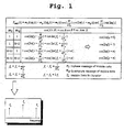
- In the MSK modulation-based wobble addressing method, as shown in Fig. 1, two different frequencies f1 and f2 and two different phases P1 and P2 are decided based on a combination of an inphase message mI and quadrature message mQ of wobble data to be formed and recorded as physical address information on the optical disc, and wobble signals with four different waveforms are generated according to the two different frequencies and the two different phases.
- For example, the first one f1 of the two different frequencies f1 and f2 is higher than a center frequency fc and the second frequency f2 is lower than the center frequency fc. Also, the first one P1 of the two different phases P1 and P2 is zero and the second phase P2 is 180° (π). As a result, an MSK-modulated wobble signal having four different waveforms generated according to the first and second frequencies and the first and second phases, namely, cos(2πf 2 t+0), cos(2πf 1 t+0), cos(2πf 1 t + π) and cos(2πf 2 t + π) can be expressed by the following equation:
- On the other hand, a combination of the inphase message mI and quadrature message mQ of wobble data to be recorded on the optical disc must always be expressed as (mI,mQ ). In this regard, in the case where wobble data to be recorded on the optical disc has a bit stream '11010000' as shown in Fig. 2, a combination (mI , mQ ) of the inphase message mI and quadrature message mQ of the first bit '1' becomes (1,1) by a combination with the second bit '1', a message combination (mI ,mQ ) of the second bit '1' becomes (0,1) by a combination with the third bit '0', a message combination (mI ,mQ ) of the third bit '0' becomes (1,0) by a combination with the fourth bit '1', a message combination (mI,mQ ) of 'the fourth bit '1' becomes (0,1) by a combination with the fifth bit '0', and a message combination (mI ,mQ ) of the fifth bit '0' becomes (0,0) by a combination with the sixth bit '0". That is, a combination (mI ,mQ ) of the inphase message mI and quadrature message mQ of a wobble data bit is any one of (1,1), (1,0), (0,1) and (0,0), and signals corresponding thereto have four different waveforms with two different frequencies and two different phases, as shown in Fig. 2.
- Therefore, an MSK-modulated wobble signal SMSK (t) has a smoothly consecutive waveform resulting from the summing-up of the above signals, so it can be more accurately recorded on the optical disc.
- On the other hand, a conventional decoding apparatus for decoding an MSK-modulated wobble signal read from the optical disc comprises, as shown in Fig. 3,
analog mixers interval integrators phase decision devices logic circuit 16. - The
analog mixers interval integrators phase decision devices logic circuit 16 interleaves the decided phases to restore a binary sequence of bit stream data (i.e., original wobble data). As a result, an MSK-modulated wobble signal, recorded in a smoothly consecutive waveform according to the MSK modulation method, is demodulated into wobble data with no high-frequency noise by the decoding apparatus with the above-mentioned construction. - However, the above-mentioned conventional decoding apparatus has a disadvantage in that a complex hardware configuration is required to multiply a wobble signal read from the optical disc by the first and second encoding frequencies 1(t) and 2(t) and integrate the resulting signals.
- Further, in the case where the optical disc varies in rotational speed by a spindle servo operation of an optical disc apparatus, the wobble signal read from the optical disc varies in frequency, so the first and second encoding frequencies 1(t) and 2(t) applied respectively to the
analog mixers - Therefore, the present invention has been made in view of the above problems, and it is an object of the present invention to provide an apparatus and method for encoding a wobble signal to be recorded as physical address information on a writable optical disc, in such a manner that the wobble signal can be accurately decoded according to a simple hardware configuration and algorithm in a decoding process.
- It is another object of the present invention to provide an apparatus and method for accurately decoding a wobble signal read from an optical disc according to a simple hardware configuration and algorithm.
- In accordance with one aspect of the present invention, the above and other objects can be accomplished by the provision of a method for encoding wobble data to be recorded as physical address information on an optical disc in a minimum shift keying modulation manner, comprising the steps of a) combining an inphase message and quadrature message of the wobble data; and b) deciding a first frequency f1 and second frequency f2 and a first phase and second phase of a corresponding wobble signal according to the combination of the inphase message and quadrature message such that the first frequency second frequency are f 1 = k / 2Tb and f 2 = p / 2Tb (Tb = wobble data bit duration) under the condition that k,p = natural numbers and k-p = 1, respectively, and modulating the wobble signal on the basis of the decided first and second frequencies and first and second phases.
- In accordance with another aspect of the present invention, there is provided an apparatus for encoding wobble data to be recorded as physical address information on an optical disc in a minimum shift keying modulation manner, comprising combination means for combining an inphase message and quadrature message of the wobble data; decision means for deciding a first frequency f1 and second frequency f2 and a first phase and second phase of a corresponding wobble signal according to the combination of the inphase message and quadrature message such that the first frequency and second frequency are f 1 = k / 2Tb and f 2 = p / 2Tb (Tb = wobble data bit duration) under the condition that k,p = natural numbers and k-p = 1, respectively; and modulation means for modulating a wobble signal having four types of waveforms on the basis of the decided first and second frequencies and first and second phases.
- In accordance with a further aspect of the present invention, there is provided a method for decoding a wobble signal read from an optical disc, comprising the steps of a) band pass filtering an analog wobble signal read from the optical disc and converting the filtered wobble signal into a digital wobble signal; b) detecting a peak point of the converted digital wobble signal and outputting a peak detection signal with a level transition at the detected peak point; and c) detecting/outputting original wobble data on the basis of the outputted peak detection signal.
- In accordance with yet another aspect of the present invention, there is provided an apparatus for decoding a wobble signal read from an optical disc, comprising filtering means for band pass filtering an analog wobble signal read from the optical disc; analog/digital (A/D) conversion means for converting the band pass filtered analog wobble signal. into a digital wobble signal; slope detection means for detecting a slope of the converted digital wobble signal; peak detection means for generating and outputting a peak detection signal, the peak detection signal having a high level transition at a point of time that the slope changes from negative to positive, and a low level transition at a point of time that the slope changes from positive to negative; and wobble data output means for detecting/outputting original wobble data on the basis of the outputted peak detection signal.
- The above and other objects, features and other advantages of the present invention will be more clearly understood from the following detailed description taken in conjunction with the accompanying drawings, in which:
- Fig. 1 is a table showing general equations and conditions applied to wobble signal MSK modulation;
- Fig. 2 is a waveform diagram of a wobble signal MSK-modulated according to a general MSK modulation method;
- Fig. 3 is a block diagram showing the construction of a conventional decoding apparatus for decoding an MSK-modulated wobble signal;
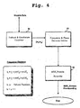
- Fig. 4 is a block diagram showing the construction of a wobble signal encoding apparatus in accordance with a preferred embodiment of the present invention;
- Fig. 5 is a waveform diagram of a wobble signal MSK-modulated by a wobble signal encoding method in accordance with the embodiment of the present invention;
- Fig. 6 is a block diagram showing the construction of a wobble signal decoding apparatus in accordance with the embodiment of the present invention;
- Fig. 7 is a waveform diagram of signals and wobble data detected and demodulated by a wobble signal decoding method in accordance with the embodiment of the present invention;
- Fig. 8 is a table showing reference information applied to the wobble signal decoding method in accordance with the embodiment of the present invention;
- Fig. 9 is a waveform diagram of analog wobble signals of a first frequency and second frequency decided by a wobble signal encoding apparatus and method in accordance with an alternative embodiment of the present invention;
- Fig. 10 is a block diagram showing the construction of a wobble, signal decoding apparatus in accordance with the second embodiment of the present invention; and
- Fig. 11 is a waveform diagram of signals and wobble data detected and demodulated by a wobble signal decoding method in accordance with the second embodiment of the present invention.
-
- With reference to Fig. 4, there is shown in block form the construction of an encoding apparatus for encoding a wobble signal to be recorded on an optical disc in accordance with a preferred embodiment of the present invention. As shown in this drawing, the encoding apparatus comprises an inphase/quadrature message combiner 20, a frequency/
phase decision device 21, and an MSK wobble signal recorder 22. - The inphase/quadrature message combiner 20 always combines an inphase message mI and quadrature message mQ of wobble data to be recorded as physical address information on the optical disc into (mI, mQ ), as stated previously.
- The frequency/
phase decision device 21 decides two different frequencies f1 and f2 and two different phases. P1 and P2 according to a value of the combination (mI , mQ ), namely, any one of (1,1), (1,0), (0,1) and (0,0) to generate an MSK-modulated wobble signal having four different waveforms, namely, cos(2πf2t+0), cos(2πf 1 t+0), cos(2πf 1 t+π) and cos(2πf 2 t+π). At this time, the first and second frequencies are decided to have values satisfying the following equations, respectively:f f - In other words, the frequency/
phase decision device 21 decides the first and second frequencies f1 and f2 to have values satisfying theequations - A detailed description will hereinafter be given of the case where the first frequency and second frequency are decided respectively as, for example, f 1 = 3 / 2Tb and f 2 = 2 / 2Tb satisfying k = 3, p = 2 and k-p = 1.
- A combination of the inphase message mI and quadrature message mQ of wobble data to be recorded on the optical disc must always be expressed as (mI , mQ ). In this regard, in the case where wobble data to be recorded on the optical disc has a bit stream '00110' as shown in Fig. 5, a message combination (mI, mQ ) of the first bit '0' becomes (0,0) by a combination with the second bit '0', a message combination (mI ,mQ ) of the second bit '0' becomes (1,0) by a combination with the third bit '1', a message combination (mI, mQ ) of the third bit '1' becomes (1,1) by a combination with the fourth bit '1', and a message combination (mI , mQ ) of the fourth bit '1' becomes (0,1) by a combination with the fifth bit '0'.
- Accordingly, a pulse signal of cos(2πf 2 t+π) having the second frequency f2 and 180° phase (π) is generated by the message combination (mI , mQ = 0,0) of the first bit '0', and a pulse signal of cos(2πf 1 t+0) having the first frequency f1 and zero phase is generated by the message combination (mI , mQ = 1,0) of the second bit '0'.
- Also, a pulse signal of cos(2πf 2 t+0) having the second frequency f2 and zero phase is generated by the message combination (mI ,mQ = 1,1) of the third bit '1', and a pulse signal of cos(2πf 1 t + π) having the first frequency f1 and 180° phase (π) is generated by the message combination (mI , mQ = 0,1) of the fourth bit '1'.
- That is, satisfying the above conditions that k and p are natural numbers and k-p = 1, the MSK-modulated wobble signal has a minimum or maximum peak point at a point of time that the first frequency and the second frequency change.
- The MSK wobble signal recorder 22 forms and records a wobble-shaped groove on the optical disc using the wobble signal MSK-modulated in the above manner.
- Fig. 6 shows the construction of a wobble signal decoding apparatus in accordance with the embodiment of the present invention, which is adapted to decode a wobble signal read from the optical disc where a wobble-shaped groove is formed using a wobble signal MSK-modulated in the above manner. As shown in this drawing, the wobble signal decoding apparatus comprises a band pass filter (BPF) 30, an analog/digital (A/D) converter (ADC) 31, a
slope detector 32, apeak detector 33, a wobble phase locked loop (PLL)circuit 34, acomponent indicator 35, a frequency/phase detector 36, and anaddress decoder 37. - The
band pass filter 30 filters an analog wobble signal read from the optical disc at a predetermined frequency band to remove a high-frequency noise component, etc. therefrom. The A/D converter 31 converts the band pass filtered analog wobble signal into a digital wobble signal. - The
slope detector 32 detects a slope of the A/D-converted digital wobble signal. Thepeak detector 33 detects a point where the detected slope changes from negative to positive as a minimum peak point, and a point where the detected slope changes from positive to negative as a maximum peak point, respectively, and outputs a peak detection signal corresponding to the detected minimum and maximum peak points. - The
wobble PLL circuit 34 outputs a wobble PLL signal synchronized with the peak detection signal. At this time, the wobble PLL signal is synchronized with a lowest one of a plurality of frequencies (i.e., a signal with a longest period) included in the peak detection signal. - The
component indicator 35 repeatedly outputs a component indicator signal CI with a high/low level transition at a rising edge of the wobble PLL signal. - For example, as shown in Fig. 7, in the case where an MSK-modulated wobble signal outputted through 'the
band pass filter 30 and A/D converter 31 is asignal 1 ○ having four waveforms (namely, cos(2πf 2 t+π), cos(2πf 1 t+0), cos(2πf 2 t+0) and cos(2πf 1 t+π)) with two different frequencies f1 and f2 and two different phases, thepeak detector 33 detects a point where a slope of the MSK-modulated wobble signal changes from negative to positive as a minimum peak point, and a point where the wobble signal slope changes from positive to negative as a maximum peak point, respectively, and outputs apeak detection signal 2 ○ with high and low level transitions at the minimum and maximum peak points. - On the other hand, the
wobble PLL circuit 34 outputs awobble PLL signal 3 ○ which has high and low levels repeatedly 50% by 50% synchronously with the second frequency f2 of the peak detection signal. Thecomponent indicator 35 outputs acomponent indicator signal 4 ○ with a high/low level transition at a rising edge of the wobble PLL signal. - The component indicator signal, peak detection signal and wobble PLL signal are inputted to the frequency/
phase detector 36. As shown in Fig. 8, in each interval a ○, b ○, c ○, d ○, ... corresponding to one wobble data bit duration Tb, the frequency/phase detector 36 XORes the peak detection signal PD and the wobble PLL signal PLL and integrates the XORed resultAlso, the frequency/
phase detector 36 XORes the peak detection signal PD and the component indicator signal CI and integrates the XORed resultThen, the frequency/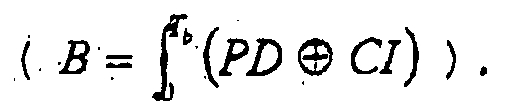
phase detector 36 detects whether each of the integrated values A and B approximates which one of a plurality of predetermined threshold values (for example, Th1 = 0, Th2 = 33, Th3 = 50, Th4 = 66 and Th5 = 100) - Accordingly, because, in the interval @ shown in Fig. 7, the value A obtained by XORing the peak detection signal PD and the wobble PLL signal PLL and integrating the XORed result approximates Th5 = 100 assuming that 100 is the maximum, the frequency/
phase detector 36 detects the second frequency f2 and 180° phase with reference to a demodulation table shown in Fig. 8. In the interval b ○ in Fig. 7, the value A obtained by XORing the peak detection signal PD and the wobble PLL signal PLL and integrating the XORed result approximates Th3 = 50 assuming that 100 is the maximum. As a result, the frequency/phase detector 36 detects the first frequency f1 with reference to the demodulation table. Also in this interval b ○, the value B obtained by XORing the peak detection signal PD and the component indicator signal CI and integrating the XORed result approximates Th2 = 33 assuming that 100 is the maximum, so the frequency/phase detector 36 detects the zero phase. Further, because, in the interval © shown in Fig. 7, the value A obtained by XORing the peak detection signal PD and the wobble PLL signal PLL and integrating the XORed result approximates Th1 = 0 assuming that 100 is the maximum, the frequency/phase detector 36 detects the second frequency f2 and zero phase with reference to the demodulation table. In the interval d ○ in Fig. 7, the value A obtained by XORing the peak detection signal PD and the wobble PLL signal PLL and integrating the XORed result approximates Th3 = 50 assuming that 100 is the maximum. As a result, the frequency/phase detector 36 detects the first frequency f1 with reference to the demodulation table. Also in this interval d ○, the value B obtained by XORing the peak detection signal PD and the component indicator signal CI and integrating the XORed result approximates Th4 = 66 assuming that 100 is the maximum, so the frequency/phase detector 36 detects the 180° phase. - In this manner, the frequency/
phase detector 36 simply detects the frequency and phase of the MSK-modulated wobble signal in each interval corresponding to one wobble data bit duration Tb, and outputs information regarding the detected frequency and phase to theaddress decoder 37. - On the other hand, the
address decoder 37 detects a value of (mI , mQ ) combined in the MSK wobble signal modulation process in the reverse order on the basis of the detected frequency and phase. That is, as shown in Fig. 8, in the case where the second frequency f2 and 180° phase are detected in the interval a ○ in Fig. 7, the (mI ,mQ ) value is (0,0), so theaddress decoder 37 decodes a corresponding wobble data bit value into '0'. In'the case where the first frequency f1 and zero phase are detected in the interval b ○ in Fig. 7, the (mI ,mQ ) value is (1,0), so theaddress decoder 37 decodes a corresponding wobble data bit value into '0'. In the case where the second frequency f2 and zero phase are detected in the interval © in Fig. 7, the (mI , mQ ) value is (1,1), so theaddress decoder 37 decodes a corresponding wobble data bit value into '1'. In the case where the first frequency f1 and 180° 'phase are detected in the interval d ○ in Fig. 7, the (mI,mQ ) value is (0,1), so theaddress decoder 37 decodes a corresponding wobble data bit value into '1'. In this manner, theaddress decoder 37 sequentially decodes a bit stream of original wobble data '0011..'. - As described above, the wobble signal decoding apparatus and method are adapted to demodulate an MSK-modulated wobble signal in the following manner. Namely, the decoding apparatus and method simply extract information regarding a modulation frequency and phase of the MSK-modulated wobble signal using a peak detection signal with a level transition at a peak point of the wobble signal and a wobble PLL signal synchronized with the peak detection signal, and demodulate the MSK-modulated wobble signal on the basis of the extracted frequency and phase information. Therefore, a hardware configuration for demodulation of an MSK-modulated wobble signal can be simplified and a stable wobble signal demodulation operation can be performed even though a wobble signal read from the optical disc varies in frequency.
- However, in order to obtain the above effects, a wobble PLL circuit must be provided and an algorithm and hardware configuration for discrimination of a modulation frequency and phase are required. A detailed description will hereinafter be given of a more improved wobble signal encoding apparatus and method and wobble signal decoding apparatus and method which can allow the wobble PLL circuit and the algorithm and hardware configuration for modulation frequency/phase discrimination to be omitted.
- The frequency/
phase decision device 21 in Fig. 4 decides the first and second frequencies f1 and f2 to have values satisfying theequations - That is, the first frequency f1 and the second frequency f2 are decided in such a manner that the value k of the first frequency f1 is an odd number which is 3 or more, namely, k = 2n+1 and the value p of the second frequency f2 is an even number which is 2 or more, namely, p = 2n.
- For example, in the case where the value k of the first frequency f1 is '3' and the value p of the second frequency f2 is '2', the first frequency f1 and the second frequency f2 become f 1 = 3 / 2Tb and f 2 = 2 / 2Tb , respectively. In this case, as shown in Fig. 9, each of the analog wobble signals 41 and 42 based on the first frequency f1 is contrary at its start and
end peaks end peaks - Thus, the same operation as pre-coding by an XOR operation is performed which outputs '1' if the current data value and the next data value are different and '0' if they are equal. As a result, the respective analog wobble signals have the same waveforms as those by direct modulations of pre-coded data, so they are directly connected with the original wobble bit data.
- In other words, because the analog wobble signal based on the first frequency f1 is contrary at the start and end peaks, it is the same as a directly modulated signal of the original wobble bit data '1'. Also, the analog wobble signal based on the second frequency f2 is equal at the start and end peaks, it is the same as a directly modulated signal of the original wobble bit data '0'.
- Fig. 10 shows the construction of the wobble signal decoding apparatus in accordance with the second embodiment of the present invention, which is adapted to decode a wobble signal read from the optical disc where a wobble-shaped groove is formed using a wobble signal MSK-modulated in the above manner. As shown in this drawing, the wobble signal decoding apparatus comprises a
band pass filter 50, an A/D converter 51, aslope detector 52, apeak detector 53, aclock detector 54, abit detector 55, asynchronous detector 56 and anaddress decoder 57. - The
band pass filter 50 filters an analog wobble signal read from the optical disc at a predetermined frequency band to remove a high-frequency noise component, etc. therefrom. The A/D converter 51 converts the band pass filtered analog wobble signal into a digital wobble signal. - The
slope detector 52 detects a slope of the A/D-converted digital wobble signal. Thepeak detector 53 detects a point where the detected slope changes from negative to positive as a minimum peak point, and a point where the detected slope changes from positive to negative as a maximum peak point, respectively, and outputs a peak detection signal corresponding to the detected minimum and maximum peak points. - For example, as shown in Fig. 11, if the original wobble bit data '0100111011' is XORed and pre-coded, the pre-coded data becomes '110100110'. If the pre-coded data is modulated into an analog wobble signal by the first frequency f1 and second frequency f2, the modulated wobble signal has a pulse waveform with opposite or equal levels at its start and end peaks.
- As a result, the
peak detector 53 outputs a peak detection signal having two types of different level transition periods. At this time, theclock detector 54 detects the level transition periods, respectively, and detects/outputs a bit clock signal of a certain period which is the least common multiple of the two types of different level transition periods. - The bit clock signal of the certain period is a clock signal of the same period as a bit transition period of the original wobble bit data, as shown in Fig. 11. The
bit detector 55 detects a level value of the peak detection signal from thepeak detector 53 at a falling edge of the bit clock signal. - At this time, the
bit detector 55 detects/outputs wobble data of '0' if the level value of the peak detection signal detected at the falling edge of the bit clock signal is low, and wobble data of '1' if the detected level value is high. - Therefore, the decoded data detected/outputted from the
bit detector 55 is demodulated into a value of '0100111011' which is the same as the original wobble data sequence, as shown in Fig. 11. Consequently, as stated previously, there is no need to employ the wobble PLL circuit, and the algorithm and hardware configuration for modulation frequency and phase discrimination can be omitted. - As apparent from the above description, according to the present invention, a wobble signal read from an optical disc can be accurately decoded in a simple manner.
- Although the preferred embodiments of the present invention have been disclosed for illustrative purposes, those skilled in the art will appreciate that various modifications, additions and substitutions are possible, without departing from the scope and spirit of the invention as disclosed in the accompanying claims.
Claims (25)
- A method for encoding wobble data to be recorded as physical address information on an optical disc in a minimum shift keying modulation manner, comprising the steps of:a) combining an inphase message and quadrature message of said wobble data; andb) deciding a first frequency f1 and second frequency f2 and a first phase and second phase of a corresponding wobble signal according to the combination of said inphase message and quadrature message such that said first frequency and second frequency are f 1 = k / 2Tb and f 2 = p / 2Tb (Tb = wobble data bit duration) under the condition that k,p = natural numbers and k-p = 1, respectively, and modulating said wobble signal on the basis of the decided first and second frequencies and first and second phases.
- The method as set forth in claim 1, wherein said wobble signal modulated at said step b) has a minimum or maximum peak point at a point of time that said first frequency and second frequency change.
- The method as set forth in claim 1, wherein said step b) includes the step of deciding said first frequency and second frequency to have values satisfying f 1 = k / 2Tb and f 2 = p / 2Tb (Tb = wobble data bit duration) under the condition that k,p = natural numbers, k-p = 1 and k = 2n+1 (an odd number which is 3 or more), respectively, and modulating said wobble signal on the basis of the decided first and second frequencies and first and second phases.
- The method as set forth in claim 3, wherein said wobble signal modulated at said step b) has a minimum or maximum peak point at a point of time that said first frequency and second frequency change, said peak point being given a signal level directly connected with original wobble bit data.
- An apparatus for encoding wobble data to be recorded as physical address information on an optical disc in a minimum shift keying modulation manner, comprising:combination means for combining an inphase message and quadrature message of said wobble data;decision means for deciding a first frequency f1 and second frequency f2 and a first phase and second phase of a corresponding wobble signal according to the combination of said inphase message and quadrature message such that said first frequency and second frequency are f 1 = k / 2Tb and f 2 = p / 2Tb (Tb = wobble data bit duration) under the condition that k,p = natural numbers and k-p = 1, respectively; andmodulation means for modulating a wobble signal having four types of waveforms on the basis of the decided first and second frequencies and first and second phases.
- The apparatus as set forth in claim 5, wherein said wobble signal modulated by said modulation means has a minimum or maximum peak point at a point of time that said first frequency and second frequency change.
- The apparatus as set forth in claim 5, wherein said decision means is adapted to decide said first frequency and second frequency to have values satisfying f 1 = k / 2Tb and f 2 = p / 2Tb (Tb = wobble data bit duration) under the condition that k,p = natural numbers, k-p = 1 and k = 2n+1 (an odd number which is 3 or more), respectively, and said modulation means is adapted to modulate said wobble signal on the basis of the decided first and second frequencies and first and second phases.
- The apparatus as set forth in claim 7, wherein said wobble signal modulated by said modulation means has a minimum or maximum peak point at a point of time that said first frequency and second frequency change, said peak point being given a signal level directly connected with original wobble bit data.
- A method for decoding a wobble signal read from an optical disc, comprising the steps of:a) band pass filtering an analog wobble signal read from the optical disc and converting the filtered wobble signal into a digital wobble signal;b) detecting a peak point of the converted digital wobble signal and outputting a peak detection signal with a level transition at the detected peak point; andc) detecting/outputting original wobble data on the basis of the outputted peak detection signal.
- The method as set forth in claim 9, wherein said step c) includes the steps of:c-1) outputting a wobble phase locked loop (PLL) signal synchronized with a long-period pulse of said peak detection signal outputted at said step b), and a component indicator signal with a level transition at a rising edge of said wobble PLL signal;c-2) XORing and integrating a level of said peak detection, signal and a level of said wobble PLL signal and XORing and integrating the level of said peak detection signal and a level of said component indicator signal;c-3) comparing each of the integrated values with a plurality of predetermined threshold values and detecting an inphase message and quadrature message of said digital wobble signal in accordance with the compared results; andc-4) demodulating the detected inphase message and quadrature message in the reverse order of their combination to detect/output the original wobble data.
- The method as set forth in claim 9, wherein said peak detection signal outputted at said step b) has a high level transition at a point of time that a slope of said digital wobble signal changes from negative to positive, and a low level transition at a point of time that the slope of said digital wobble signal changes from positive to negative.
- The method as set forth in claim 10, wherein said step c-3) includes the step of, if a value obtained by XORing the level of said peak detection signal and the level of said wobble PLL signal and integrating the XORed result approximates 0 assuming that 100 is the maximum, determining said digital wobble signal to have a second frequency of a first frequency f 1 = k / 2Tb and the second frequency f 2 = p / 2Tb (Tb = wobble data bit duration, k,p = natural numbers, and k-p = 1), and a zero phase and detecting a combination of said inphase message and quadrature message of said digital wobble signal as (1,1) corresponding to the second frequency and zero phase.
- The method as set forth in claim 10, wherein said step c-3) includes the step of, if a value obtained by XORing the level of said peak detection signal and the level of said wobble PLL signal and integrating the XORed result approximates 100 assuming that 100 is the maximum, determining said digital wobble signal to have a second frequency of a first frequency f 1 = k / 2Tb and the second frequency f 2 = p / 2Tb (Tb = wobble data bit duration, k,p = natural numbers, and k-p = 1), and a 180° phase and detecting a combination of said inphase message and quadrature message of said digital wobble signal as (0,0) corresponding to the second frequency and 180° phase.
- The method as set forth in claim 10, wherein said step c-3) includes the step of determining said digital wobble signal to have a first frequency of the first frequency f 1 = k / 2Tb and a second frequency f 2 = p / 2Tb (Tb = wobble data bit duration, k,p = natural numbers, and k-p = 1) if a value obtained by XORing the level of said peak detection signal and the level of said wobble PLL signal and integrating the XORed result approximates 50 assuming that 100 is the maximum, determining said digital wobble signal to have a zero phase if a value obtained by XORing the level of said peak detection signal and the level of said component indicator signal and integrating the XORed result approximates 33 assuming that 100 is the maximum, and detecting a combination of said inphase message and quadrature message of said digital wobble signal as (1,0) corresponding to the first frequency and zero phase.
- The method as set forth in claim 10, wherein said step c-3) includes the step of determining said digital wobble signal to have a first frequency of the first frequency f 1 = k / 2Tb and a second frequency f 2 = p / 2Tb (Tb = wobble data bit duration, k,p = natural numbers, and k-p = 1) if a value obtained by XORing the level of said peak detection signal and the level of said wobble PLL signal and integrating the XORed result approximates 50 assuming that 100 is the maximum, determining said digital wobble signal to have a 180° phase if a value obtained by XORing the level of said peak detection signal and the level of said component indicator signal and integrating the XORed result approximates 66 assuming that 100 is the maximum, and detecting a combination of said inphase message and quadrature message of said digital wobble signal as (0,1) corresponding to the first frequency and 180° phase.
- The method as set forth in claim 9, wherein said step c) includes the steps of:c-1) monitoring a level transition period of said peak detection signal outputted at said step b) to detect a wobble data bit clock of a certain period; andc-2) detecting/outputting the original wobble data on the basis of a level value of said peak detection signal at a falling edge of the detected wobble data bit clock.
- The method as set forth in claim 16, wherein said step c-1) includes the step of monitoring two types of different level transition periods of said peak detection signal to detect/output as said wobble data bit clock a clock of a period which is the least common multiple of the two types of different periods.
- The method as set forth in claim 16, wherein said step c-2) includes the step of detecting/outputting wobble data of '0' if the level value of said peak detection signal is low, and wobble data of '1' if the level value is high.
- An apparatus for decoding a wobble signal read from an optical disc, comprising:filtering means for band pass filtering an analog wobble signal read from the optical disc;analog/digital (A/D) conversion means for converting the band pass filtered analog wobble signal into a digital wobble signal;slope detection means for detecting a slope of the converted digital wobble signal;peak detection means for generating and outputting a peak detection signal, said peak detection signal having a high level transition at a point of time that said slope changes from negative to positive, and a low level transition at a point of time that said slope changes from positive to negative; andwobble data output means for detecting/outputting original wobble data on the basis of the outputted peak detection signal.
- The apparatus as set forth in claim 19, wherein said wobble data output means includes:wobble phase locked loop (PLL) means for generating and outputting a wobble PLL signal synchronized with a long-period pulse of said peak detection signal;component indicator means for generating and outputting a component indicator signal with a level transition at a rising edge of said wobble PLL signal;frequency/phase detection means for XORing and integrating a level of said peak detection signal and a level of said wobble PLL signal, XORing and integrating the level of said peak detection signal and a level of said component indicator signal, comparing each of the integrated values with a plurality of predetermined threshold values and detecting an inphase message and quadrature message of said digital wobble signal in accordance with the compared results; anddemodulation means for demodulating the detected inphase message and quadrature message in the reverse order of their combination to detect/output the original wobble data.
- The apparatus as set forth in claim 20, wherein said frequency/phase detection means is adapted to compare each of said integrated values with said predetermined threshold values and selectively detect the combination of said inphase message and quadrature message of said digital wobble signal as any one of (0,0), (0,1), (1,0) and (1,1) in accordance with the compared results.
- The apparatus as set forth in claim 20, wherein said demodulation means is adapted to demodulate corresponding wobble data into 0, 1, 0 or 1 if the combination of said inphase message and quadrature message is (0,0), (0,1), (1,0) or (1,1).
- The apparatus as set forth in claim 19, wherein said wobble data output means includes:clock detection means for monitoring a level transition period of said peak detection signal to detect a wobble data bit clock of a certain period; andbit detection means for detecting/outputting the original wobble data on the basis of a level value of said peak detection signal at a falling edge of the detected wobble data bit clock.
- The apparatus as set forth in claim 23, wherein said clock detection means is adapted to monitor two types of different level transition periods of said peak detection signal to detect/output as said wobble data bit clock a clock of a period which is the least common multiple of the two types of different periods.
- The apparatus as set forth in claim 23, wherein said clock detection means is adapted to detect/output wobble data of '0' if the level value of said peak detection signal is low, and wobble data of '1' if the level value is high.
Applications Claiming Priority (4)
| Application Number | Priority Date | Filing Date | Title |
|---|---|---|---|
| KR2001071610 | 2001-11-17 | ||
| KR10-2001-0071610A KR100513337B1 (en) | 2001-11-17 | 2001-11-17 | Apparatus and method for modulating and demodulating wobble signal on optical disc |
| KR10-2001-0082835A KR100513327B1 (en) | 2001-12-21 | 2001-12-21 | Apparatus and method for modulating and demodulating wobble signal on optical disc |
| KR2001082835 | 2001-12-21 |
Publications (2)
| Publication Number | Publication Date |
|---|---|
| EP1320098A2 true EP1320098A2 (en) | 2003-06-18 |
| EP1320098A3 EP1320098A3 (en) | 2007-06-06 |
Family
ID=26639463
Family Applications (1)
| Application Number | Title | Priority Date | Filing Date |
|---|---|---|---|
| EP02025814A Withdrawn EP1320098A3 (en) | 2001-11-17 | 2002-11-18 | Apparatus and method for encoding wobble signal to be recorded on optical disc, and apparatus and method for decoding wobble signal read from optical disc |
Country Status (3)
| Country | Link |
|---|---|
| US (1) | US7352674B2 (en) |
| EP (1) | EP1320098A3 (en) |
| JP (1) | JP3789423B2 (en) |
Families Citing this family (16)
| Publication number | Priority date | Publication date | Assignee | Title |
|---|---|---|---|---|
| JP2002279640A (en) | 2001-03-21 | 2002-09-27 | Ricoh Co Ltd | Wobble detection circuit and its device |
| PT1926093E (en) * | 2001-07-02 | 2010-09-30 | Koninkl Philips Electronics Nv | Record carrier and apparatus for scanning the record carrier |
| JP3566690B2 (en) | 2001-12-07 | 2004-09-15 | 株式会社リコー | Wobble signal detection circuit and optical disk device |
| US7356186B2 (en) * | 2002-08-23 | 2008-04-08 | Kulas Charles J | Digital representation of audio waveforms using peak shifting to provide increased dynamic range |
| TWI261225B (en) * | 2003-04-10 | 2006-09-01 | Via Optical Solution Inc | Method and related apparatus for evaluating beta-parameter according to results of read data sliced with different slicing levels while performing optimal power control of optical disk drive |
| EP1489612B1 (en) * | 2003-06-16 | 2017-05-03 | Thomson Licensing | Wobble demodulation for high density optical recording media |
| EP1489611A1 (en) * | 2003-06-16 | 2004-12-22 | Deutsche Thomson-Brandt Gmbh | Wobble demodulation for high density optical recording media |
| TWI301969B (en) * | 2004-10-12 | 2008-10-11 | Mediatek Inc | Method and apparatus for detecting a physical mark in a signal read from an optical disk |
| EP1814111A4 (en) * | 2004-10-20 | 2008-08-13 | Matsushita Electric Industrial Co Ltd | RECORDING DEVICE, REPRODUCING DEVICE, AND RECORDING / REPRODUCING DEVICE |
| KR100615617B1 (en) * | 2004-12-17 | 2006-08-25 | 삼성전자주식회사 | Optical disc wobble information detection device and method |
| KR100574027B1 (en) * | 2004-12-17 | 2006-04-26 | 삼성전자주식회사 | Optical disc wobble information detection device and method |
| US7978579B1 (en) * | 2006-09-18 | 2011-07-12 | Marvell International Ltd. | HD DVD wobble detection circuit |
| JP4829138B2 (en) * | 2007-01-26 | 2011-12-07 | 株式会社東芝 | Optical disc apparatus and ADIP decoding apparatus |
| US8270266B2 (en) * | 2008-04-17 | 2012-09-18 | Mediatek Inc. | Methods and devices for detecting wobbles on an optical disc |
| US8582405B1 (en) * | 2012-09-25 | 2013-11-12 | Oracle International Corporation | Matched pattern signal decoding |
| US9292475B1 (en) * | 2013-12-24 | 2016-03-22 | Glooko Inc. | Method and system for processing information |
Citations (3)
| Publication number | Priority date | Publication date | Assignee | Title |
|---|---|---|---|---|
| WO2003005350A1 (en) | 2001-07-02 | 2003-01-16 | Koninklijke Philips Electronics N.V. | Record carrier and apparatus for scanning the record carrier |
| EP1369851A1 (en) | 2001-03-12 | 2003-12-10 | Sony Corporation | Disc-shaped recording medium, disc-state recording medium cutting apparatus, and disc drive apparatus |
| EP1372142A1 (en) | 2001-03-19 | 2003-12-17 | Sony Corporation | Method and apparatus for recording address information on disc medium |
Family Cites Families (4)
| Publication number | Priority date | Publication date | Assignee | Title |
|---|---|---|---|---|
| JP3906557B2 (en) * | 1998-04-21 | 2007-04-18 | ソニー株式会社 | Signal processing circuit |
| JP3348660B2 (en) * | 1998-10-09 | 2002-11-20 | 双葉電子工業株式会社 | Symbol synchronizer and frequency hopping receiver |
| TW468171B (en) * | 1999-06-02 | 2001-12-11 | Koninkl Philips Electronics Nv | Optical record carrier |
| JP2002157745A (en) * | 2000-09-07 | 2002-05-31 | Sony Corp | Disk drive |
-
2002
- 2002-11-15 JP JP2002332091A patent/JP3789423B2/en not_active Expired - Fee Related
- 2002-11-18 EP EP02025814A patent/EP1320098A3/en not_active Withdrawn
- 2002-11-18 US US10/295,948 patent/US7352674B2/en not_active Expired - Lifetime
Patent Citations (3)
| Publication number | Priority date | Publication date | Assignee | Title |
|---|---|---|---|---|
| EP1369851A1 (en) | 2001-03-12 | 2003-12-10 | Sony Corporation | Disc-shaped recording medium, disc-state recording medium cutting apparatus, and disc drive apparatus |
| EP1372142A1 (en) | 2001-03-19 | 2003-12-17 | Sony Corporation | Method and apparatus for recording address information on disc medium |
| WO2003005350A1 (en) | 2001-07-02 | 2003-01-16 | Koninklijke Philips Electronics N.V. | Record carrier and apparatus for scanning the record carrier |
Also Published As
| Publication number | Publication date |
|---|---|
| EP1320098A3 (en) | 2007-06-06 |
| US20030099180A1 (en) | 2003-05-29 |
| JP2003157623A (en) | 2003-05-30 |
| US7352674B2 (en) | 2008-04-01 |
| JP3789423B2 (en) | 2006-06-21 |
Similar Documents
| Publication | Publication Date | Title |
|---|---|---|
| EP1320098A2 (en) | Apparatus and method for encoding wobble signal to be recorded on optical disc, and apparatus and method for decoding wobble signal read from optical disc | |
| US7411889B2 (en) | Optical disc with wobbled tracks and apparatus using this optical disc | |
| JP2001357627A (en) | Information recording method and its device | |
| US8934325B2 (en) | Information recording medium, information reproducing method, and information reproducing apparatus | |
| KR100513327B1 (en) | Apparatus and method for modulating and demodulating wobble signal on optical disc | |
| KR100513337B1 (en) | Apparatus and method for modulating and demodulating wobble signal on optical disc | |
| CN100377219C (en) | Demodulation device/method of optical disk dither signal and demodulation device/method thereof | |
| US7313753B2 (en) | Detector for detecting information carried by a signal having a sawtooth-like shape | |
| US7321639B2 (en) | Demodulator and address information extractor | |
| KR100589810B1 (en) | Optical disc recording and / or playback device | |
| US7304925B2 (en) | Wobble demodulation for high density optical recording media | |
| KR100545804B1 (en) | Wobble signal detection apparatus and method in wobble phase locked loop | |
| JP4277781B2 (en) | Address information detection circuit for optical disk drive device | |
| KR20030069637A (en) | Apparatus and method for demodulating wobble signal on optical disc | |
| EP1596377A1 (en) | Recording medium, wobble cycle detection method, wobble information detection method, wobble information detection circuit, and information recording/reproduction device | |
| EP1511019B1 (en) | Wobble demodulation for high density optical recording media | |
| JP2007042201A (en) | Optical disk apparatus, and wobble reproducing method of optical disk | |
| JP3926779B2 (en) | Digital phase locked loop circuit | |
| KR20030069636A (en) | Method for demodulating wobble signal on optical disc | |
| JP2001126412A (en) | Decryption device | |
| JP2002124043A (en) | Phase modulation decode clock generation circuit, phase inversion detection circuit, phase inversion pattern detection circuit, decoding circuit, and phase modulation signal reproducing apparatus for recording medium equipped with phase modulation signal | |
| JP2005322325A (en) | Multilevel information recording method, multilevel information reproducing method, multilevel information recording apparatus, and multilevel information reproducing apparatus | |
| JP2007310975A (en) | Address information detection circuit | |
| KR20030073468A (en) | Apparatus and method for demodulating wobble signal on optical disc | |
| JP2008010069A (en) | Optical disc apparatus and control method thereof |
Legal Events
| Date | Code | Title | Description |
|---|---|---|---|
| PUAI | Public reference made under article 153(3) epc to a published international application that has entered the european phase |
Free format text: ORIGINAL CODE: 0009012 |
|
| AK | Designated contracting states |
Designated state(s): AT BE BG CH CY CZ DE DK EE ES FI FR GB GR IE IT LI LU MC NL PT SE SK TR |
|
| AX | Request for extension of the european patent |
Extension state: AL LT LV MK RO SI |
|
| PUAL | Search report despatched |
Free format text: ORIGINAL CODE: 0009013 |
|
| AK | Designated contracting states |
Kind code of ref document: A3 Designated state(s): AT BE BG CH CY CZ DE DK EE ES FI FR GB GR IE IT LI LU MC NL PT SE SK TR |
|
| AX | Request for extension of the european patent |
Extension state: AL LT LV MK RO SI |
|
| RIC1 | Information provided on ipc code assigned before grant |
Ipc: G11B 7/005 20060101ALI20070503BHEP Ipc: G11B 27/24 20060101ALI20070503BHEP Ipc: G11B 7/007 20060101ALI20070503BHEP Ipc: G11B 20/14 20060101AFI20030425BHEP Ipc: G11B 27/19 20060101ALI20070503BHEP Ipc: G11B 20/10 20060101ALI20070503BHEP |
|
| 17P | Request for examination filed |
Effective date: 20071205 |
|
| AKX | Designation fees paid |
Designated state(s): DE FR GB NL |
|
| 17Q | First examination report despatched |
Effective date: 20090311 |
|
| RAP3 | Party data changed (applicant data changed or rights of an application transferred) |
Owner name: LG ELECTRONICS, INC. |
|
| STAA | Information on the status of an ep patent application or granted ep patent |
Free format text: STATUS: THE APPLICATION IS DEEMED TO BE WITHDRAWN |
|
| 18D | Application deemed to be withdrawn |
Effective date: 20180602 |
|
| RIC1 | Information provided on ipc code assigned before grant |
Ipc: G11B 20/14 20060101AFI20030425BHEP Ipc: G11B 7/007 20060101ALI20070503BHEP Ipc: G11B 20/10 20060101ALI20070503BHEP Ipc: G11B 27/24 20060101ALI20070503BHEP Ipc: G11B 27/19 20060101ALI20070503BHEP Ipc: G11B 7/005 20060101ALI20070503BHEP |