TECHNICAL FIELD
-
The present invention relates to a recording
medium, such as a phase change type, a write-once-read
many type or an magneto-optical type, a wobble cycle
detection method and a wobble information cycle
detection method with respect to the recording medium, a
wobble information detection circuit for detecting
wobble information from the recording medium and an
information recording and reproduction apparatus.
BACKGROUND ART
-
A track is formed in a recording area on a
recording medium (optical disc) such as a DVD+R disc, a
DVD+RW disc, etc. The track plays a role of a guidance
groove for a spot of a laser light irradiated for
recording and reproduction of information.
-
The wobble (meandering) is formed in the track,
and since a wobble signal detected from the wobble has a
substantially fixed cycle, the detected wobble signal is
mainly used as rotating-speed information.
-
Moreover, information other than the above-mentioned
rotating-speed information may also be stored
in the track by modulating the wobble.
-
As information stored by the wobble, address
information indicative of an absolute position on a
recording medium is most popular.
-
Additionally, there are listed a recording
type indicative of feature of the recording medium, that
is, a size of the recording medium or whether the
recording medium is a write-once-read many type or an
overwrite type, information of recording property, that
is, parameters such as an optimum recording power, a
recording waveform or the like, and information such as
a manufacture's name.
-
Next, a description will be given of a format
of the wobble of each of CD system recording media (CD-R
disc, CD-RW disc, etc.) and DVD+ system recording media
(DVD+R disc, DVD+RW disc, etc.).
- The CD system recording medium: biphase-modulating
address information and wobbling a track with
a frequency modulation based on it (for example, refer
to Japanese Laid-Open Patent Application No. 9-212871).
-
Specifically, in the CD system recording
medium, two kinds frequencies of 22.05 kHz±1k Hz are
assigned to data o and data 1, respectively, so as to
record information using the wobble of about 10 cycles
for one bit. Moreover, probabilities of generation of
the data 0 and the data 1 are caused to be substantially
equal to each other so as to detect a clock signal from
22.05 kHz, which is the center frequency.
- The DVD+ system recording medium: phase-modulating
address information and wobbling a track base
on it.
-
In the DVD+ system recording medium, a carrier
component is extracted from a carrier wave wobble of a
carrier wave area, which occupies a large part so as to
detect a clock signal. The address information is
recorded in an address area by setting a wobble of the
same phase with the carrier wobble as data 0 and setting
a wobble of a phase different from the carrier wobble by
180 degrees as data 1.
-
However, there was a problem as shown below,
respectively, in the wobble of the CD system recording
medium and the DVD+ system recording medium mentioned
above.
-
In the format of the wobble of the CD system
recording medium, since the clock signal of 22.05 kHz is
extracted and a frequency difference representing the
data 0 and data 1 is extremely small as ±1 kHz, S/N of
the signal was low and information recording quality was
not good. Moreover, it is difficult to accurately
specify a frequency change point, and there was a
demerit that an absolute position accuracy was poor.
-
On the other hand, in the format of the wobble
of the DVD+ system recording medium, S/N of a signal can
be raised by using a phase modulation. Moreover,
absolute position accuracy is also assured, and an
advance format has been achieved.
-
However, since the modulation methods of the
wobble for synchronization and the wobble for
information are the same and the synchronization signal
and the information signal are distinguished by a
difference in the phase inverted wobble length, it takes
a time to pull-in synchronization. Moreover, since
information is recorded by the same cycle and only the
phase modulation, leakage of a wobble component between
adjacent tracks appears remarkably in degradation of
information signal, and it was difficult to progress
further high-densification of narrow track pitch while
achieving both acquisition of reliability of information
and acquisition of recording quality.
DISCLOSURE OF THE INVENTION
-
It is a general object of the present
invention to provide an improved and useful recording
medium, wobble cycle detection method, wobble
information detection circuit, and information recording
and reproduction apparatus, in which the above-mentioned
problems are eliminated.
-
A more specific object of the present
invention is to suggest a wobble format that can acquire
high-densification, high-reliability and stability in
the future recording media, and also enables to detect
wobble cycle and information according to the format.
-
In order to achieve the objects, a recording
medium of the present invention is constituted so that a
track is divided into a first area that is continuously
wobbled by a first wobble of a specific carrier wave
cycle, and a second area that is wobbled by a second
wobble that has a cycle different from the above-mentioned
first wobble and a phase determined in
response to data 0 and data 1 of information stored by a
wobble.
-
Additionally, in order to achieve the objects,
a wobble cycle detection method of the present invention
is constituted so as to multiply wobble signals of the
same signal obtained from wobbling of a track formed on
a recording medium each other by a multiplier, and input
a signal obtained by an operation of the multiplication
into a band pass filter of which a pass band is set to
about twice a frequency of a carrier wave so that a
cycle twice an output signal of the band pass filter is
set to a cycle of the carrier wave of the wobble signal.
-
Additionally, in order to achieve the objects,
a wobble information detection method of the present
invention is constituted so as to comprise a carrier
wave processing procedure of extracting a frequency
component of the first wobble from the first area of the
recording medium, a special wave processing procedure of
extracting a phase information component of the second
wobble from the second area of the above-mentioned
recording medium, an information detecting procedure of
detecting the information stored by the wobble from the
phase information component extracted by the above-mentioned
special wave processing procedure based on the
frequency component extracted by the above-mentioned
carrier wave processing procedure.
-
In order to achieve the objects, a wobble
information detection circuit is constituted so as to
comprise a wobble cycle detection circuit that detects a
cycle of the carrier wave from a wobble signal obtained
from wobbling of the track formed on the recording
medium, a clock signal generation circuit that generates
a second clock signal of a twice cycle of the carrier
wave based on the cycle of the carrier wave detected by
the wobble cycle detection circuit, and a special wave
wobble detection circuit that indicates a position or a
phase of the second wobble of the above-mentioned second
area based on the above-mentioned second clock signal.
-
In order to achieve the objects, an
information recording and reproduction apparatus of the
present invention is constituted so as to be mounted
with the wobble information detection circuit, wherein
an access is made to a target position of the above-mentioned
recording medium based on information detected
by the wobble information detection circuit so as to
perform recording or reproduction of information on the
above-mentioned recording medium.
-
The recording medium, the wobble cycle
detection method, the wobble information detection
method, the wobble information detection circuit, and
the information recording and reproduction apparatus
according to the present invention can suggest a format
of a wobble, which is capable of acquiring future high-densification,
reliability and stability, on a recording
medium, and can detect a cycle of a wobble and
information according to the format.
BRIEF DESCRIPTION OF DRAWINGS
-
Other objects, features and advantages of the
present invention will become more apparent from the
following detailed description when read in conjunction
with the accompanied drawings.
- FIG. 1 is an illustration showing a structure
of a general recording media that is also applicable to
a mode for carrying out the present invention.
- FIG. 2 is an illustration for explaining a
phenomenon in which an amplitude of a wobble signal is
fluctuated in a recording medium according to an
embodiment of the present invention.
- FIG. 3 is an illustration for explaining a
format of a wobble formed on a track of a recording
media according to a first embodiment through a fourth
embodiment of the present invention.
- FIG. 4 is also an illustration for explaining
the format of the wobble formed on the track of the
recording media according to the first embodiment
through the fourth embodiment of the present invention.
- FIG. 5 is an illustration showing an example
of a wobble form in which bit 0 representing data 0 and
bit 1 representing data 1 are distinguished in the
recording medium according to the embodiments of the
present invention.
- FIG. 6 is a waveform chart showing an example
of a wobble waveform in which a multiple of a cycle of a
carrier wave wobble as an example of a special wave
wobble of the recording media according to the
embodiments of the present invention.
- FIG. 7 is a waveform chart showing a wobble
waveform in a case where a cycle of the special wave
wobble is changed in its length as twice the carrier
wave wobble in the recording medium according to the
embodiments of the present invention.
- FIG. 8 is an illustration for explaining a
format of a wobble formed on a track of recording media
according to an eighth through tenth embodiments of the
present invention.
- FIG. 9 is also an illustration for explaining
the format of the wobble formed on the track of the
recording media according to the eighth to tenth
embodiments of the present invention.
- FIG. 10 is also an illustration for explaining
the format of the wobble formed on the track of the
recording media according to the eighth to tenth
embodiments of the present invention.
- FIG. 11 is an illustration for explaining a
format of a wobble formed on a track of a recording
medium according to a fourteenth embodiment of the
present invention.
- FIG. 12 is an illustration showing waveforms
of the wobbles provided in a carrier wave area, an
address area and a synchronization area of the recording
media according to the embodiments of the present
invention.
- FIG. 13 is an illustration showing a form of a
wobble and a waveform of a signal detected by the wobble
in recording media according to an eleventh and twelfth
embodiments of the present invention.
- FIG. 14 is a block diagram showing a
structured of a wobble synchronization detection circuit
that realizes a wobble synchronization detection method
according to a twenty-fourth embodiment of the present
invention and a structure of a wobble synchronization
detection circuit as a background art.
- FIG. 15 is a waveform chart showing signal
waveforms of a wobble signal input to a multiplier 32
shown in FIG. 14 and an output signal thereof.
- FIG. 16 is an illustration showing a format of
a track of recording media according to a thirteenth
embodiment and a fourteenth embodiment according to the
present invention.
- FIG. 17 is an illustration showing wobble
forms in two kinds of synchronization areas of the
recording medium according to the embodiments of the
present invention.
- FIG. 18 is an illustration showing a format
and a wobble form in two kinds of synchronization areas
of the recording media according to the thirteenth
embodiment and the fourteenth embodiment of the present
invention.
- FIG. 19 is an illustration for explaining a
specific example of a wobble modulation in recording
media according to a nineteenth embodiment through a
twenty-first embodiment of the present invention.
- FIG. 20 is also an illustration for explaining
the specific example of the wobble modulation in the
recording media according to the nineteenth embodiment
through the twenty-first embodiment of the present
invention.
- FIG. 21 is also an illustration for explaining
the specific example of the wobble modulation in the
recording media according to the nineteenth embodiment
through the twenty-first embodiment of the present
invention.
- FIG. 22 is a block diagram of a wobble
information detection circuit according to a thirtieth
embodiment through a thirty-fifth embodiment of the
present invention.
- FIG. 23 is a waveform chart showing an output
waveform of each circuit when reproducing the recording
medium of the wobble format of the type 1 shown in FIG>
12 in the wobble information detection circuit shown in
FIG. 22.
- FIG. 24 is a waveform chart showing a waveform
of an output signal of each part when demodulating using
a SIN wave signal of conditions of a phase of 0 degree
and a phase of 180 degrees in the wobble information
detection circuit shown in FIG. 22.
- FIG. 25 is an illustration for explaining a
format of recording media according to the fifteenth
embodiment and the sixteenth embodiment of the present
invention.
- FIG. 26 is an illustration for explaining a
simplest method for checking a phase state in wobble
information detection circuits according to a thirty-second
embodiment and a thirty-third embodiment of the
present invention.
- FIG. 27 is a waveform chart showing an example
of a wobble form of the format of the recording medium
according to eighteenth embodiment of the present
invention.
- FIG. 28 is a waveform chart showing a signal
waveform when demodulating the wobble form of the type A
in FIG. 27.
- FIG. 29 is a block diagram showing a structure
of information recording and reproduction apparatuses
according to a thirty-sixth embodiment and a thirty-seventh
embodiment of the present invention.
- FIG. 30 is an illustration for explaining
detection of a wobble signal from a light-receiving
element 94 through an arithmetic circuit of FIG. 29.
- FIG. 31 is a block diagram of a conceptualized
wobble information detection circuit shown in FIG. 22.
-
BEST MODE FOR CARRYING OUT THE INVENTION
-
Hereafter, a description will be given, based
on the drawings, of the best mode for carrying out the
invention.
-
FIG. 1 is an illustration showing a structure
of a general recording medium applicable also to a mode
for carrying out the present invention.
-
The recording medium 1 is an optical disc,
such as a DVD+R disc, a DVD+RW disc, etc,, and as shown
in (a) of FIG. 1, a track 2 is formed in the form of
concentric circles or spiral on a recording surface.
The track 2 consists of a groove 3 and a land 4, as
shown in (b) of FIG. 1.
-
The track 2 is formed beforehand by a
recording medium forming apparatus, and a recording
apparatus records and reproduces information along the
track of the recording medium.
-
Moreover, as rotation information, the groove
3 of the track 2 wobbles (meandering) in the recording
medium so that a signal of a fixed frequency (fixed
cycle) can be detected when it rotates at a constant
linear velocity or a constant angular velocity. This
wobbled portion is referred to as a wobble.
-
In a CD-R disc, a CD-RW disc, a DVD+R disc or
a DVD+RW disc, information such as addresses is recorded
by providing a part, which slightly changes a frequency
or a phase, while the wobble of he track 2 is regarded
as having substantially fixed frequency.
-
Moreover, although the form of the wobble has
the form of a usual wave as shown in (a) of FIG. 1 in
many cases, it is necessary to derive only a carrier
wave component, and may be a in a saw form, a triangular
waveform or a trapezoid form, etc.
-
Transmission of information by changing the
frequency or the phase of the above-mentioned wobble is
well practiced in the communication field. In
communication, since a standard frequency used at a
transmitting end and a receiving end is fixed so that
many channels can be used, a carrier wave component can
be produced using an oscillator output, which has less
frequency fluctuation.
-
Of course, although there is a case in which
the carrier wave component is extracted from a
transmitted signal, it is merely a fine-tuning and a
frequency does not change during a communication.
Furthermore, although there is an external disturbance
(noise) in the properties of the communication path, an
external disturbance does not leak in with the same band
as the frequency band used in the communication.
-
On the other hand, there is a difference with
respect to the above point in a recording medium such as
an optical disc. Although a control to maintain a
constant rotation is performed in a recording medium, it
is required to use a motor having a low stability of
rotation so as to progress a weight reduction and a
minimization of the apparatus. Accordingly, the
recording medium is unstable in its rotation, and a
linear velocity changes.
-
Therefore, it is necessary to extract a
carrier wave component form, which serves as a reference,
from the wobble on the recording medium, and it is
necessary to enables a demodulation of information,
which follows a change in a linear velocity due to a
fluctuation in rotation.
-
Another large difference is that there is
leak-in of a fixed noise in a carrier wave band of the
wobble. Since an interval between tracks on the
recording medium is reduced and narrower tan a diameter
of a light spot so as to increase a recording density at
maximum, an end of the light spot overlaps with the
wobble of the adjacent track. Therefore, the wobble
component of an adjacent track leaks in (this is
refereed to as "cross-talk"). This means that an
external disturbance of the same band as a signal to be
demodulated leaks in. Under such a circumstance, the
wobble signal detected fluctuates due to influences
thereof.
-
FIG. 2 is an illustration for explaining a
phenomenon of fluctuation in an amplitude of a wobble
signal in a recording medium. Since the signals cancel
each other as shown in (a) of FIG. 2 when the wobble of
the track 2a (referred to as "target track") on which a
light spot SP is irradiated and the wobbles of the
adjacent tracks 2b and 2c have the same phase, an
amplitude of the wobble signal of the wobble detected by
irradiation of the light spot SP is reduced.
-
On the other hand, since the signals are
intensified each other as shown in (b) of FIG. 2 when
the wobble of the track 2d on which the light spot is
irradiated and the wobbles of the adjacent tracks 2e and
2f are reverse phase, an amplitude of the wobble signal
of the wobble detected by the irradiation of the light
spot is increased.
-
That is, although there is no concept of a
cross-talk in the communication field and a transmission
close to a theoretical limit, in which an external noise
is calculated as random, merely an extremely low signal
quality is acquired by a system using the wobble of a
recording medium.
-
For example, in the DVD+R/RW format of the
optical disc, two-phase phase modulation method was
adopted so as to acquire higher stability of information
detection even with such a low quality.
-
However, in a synchronization signal which
reverses a phase by 180 degrees as a synchronization
wobble, only the reversed portion has a wobble signal
characteristic reversed from an adjacent carrier wave
wobble.
-
It should be noted that since a large part of
the wobble is a carrier wave wobble, the cross-talk
component is also considered as a carrier wave component.
Specifically, if the carrier wave wobble portion of a
target track has a phase reversed from the adjacent
wobble, an amplitude of a large part of the detected
wobble signal is large. However, since only the
synchronization wobble portion having the reversed phase
is in the same phase condition, they cancel each other
and the amplitude becomes small.
-
Therefore, according to the phase modulation
with the carrier wave cycle, a demodulation result
greatly fluctuates due to bad influences of the cross-talk,
and S/N is deteriorated. In the DVD+ system,
since not only the synchronization information but also
address information and recording-medium information
were stored by this phase modulation method, an
information demodulation performance was slightly low.
However, since the synchronization information has a
constant cycle, it was able to interpolate even if the
demodulation performance is somewhat low.
-
That is, a modulation method is needed, which
is especially strong with respect to the cross-talk,
which has not been considered as a problem in the
communication field.
-
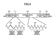
FIG. 3 and FIG. 4 are illustrations for
explaining a format of the wobble formed on the track of
a recording medium according to a first embodiment
through fourth embodiment of the present invention.
-
As shown in both FIG. 3 and FIG. 4, the
carrier wave area (hereinafter, may be referred to as
"first area") 10 that occupies a large part of the area
in the track and an address area (hereinafter, may be
referred to as "second area" that is a part of the area.
-
The carrier wave area 10 is wobbled
continuously by the carrier wave wobble (hereinafter,
referred to as "first wobble") that causes to detect a
wobble signal having a fixed cycle and a fixed phase.
-
In the carrier wave area 10, since a stable
wobble signal is detectable, it is used for generation
of a clock. In the detection of the wobble, since not
only the above-mentioned cross-talk but also the
recorded information component recorded by a user
becomes a noise, a frequency separation from this is
required.
-
Although it cannot be defined generally since
it depends on a detection circuit system, the cycle of
the carrier wave wobble is generally about 20 to 200
times the record information reference clock cycle.
-
Additionally, if it is longer than that
(frequency is low), the wobble detection cannot be
performed since it approaches a control band of a servo
system that controls to locate a detection point (spot)
to a desired position on the track.
-
In order to record address information, the
address area 11 requires two kinds of wobble forms
representing "0" (hereinafter, may be referred to as
"data 0" and "1" (hereinafter, may be referred to as
"data 1").
-
In the recording medium according to the first
embodiment, the address area 11 is subject to wobbling
by a special wave wobble (hereinafter, may be referred
to as "second wobble") that causes to detect a special
wave wobble signal (hereinafter, may be referred to as
"second wobble signal") that has a cycle different from
the carrier wave wobble signal (hereinafter, may be
referred to as "first wobble signal") detected by a
carrier waver wobble (hereinafter, may be referred to as
"first wobble") 14 and has different phases with respect
to the data 0 and the data 1 of information to be stored.
-
In the recording medium according to the
second embodiment, as shown in FIG. 3, the address area
11 is subject to wobbling by a special wave wobble 12
that causes to detect a special wave wobble signal that
has a cycle different from the carrier wave wobble
signal detected by a carrier waver wobble 14 and has a
phase corresponding to the data 0 of information to be
stored. Or, it is subject to wobbling by a special wave
wobble 13 that causes to detect a special wave wobble
signal that has a cycle different from the carrier wave
wobble signal detected by the carrier waver wobble 14
and has a phase corresponding to the data 1 of
information to be stored.
-
That is, the address area 11 is subjected to
wobbling by the special wave wobbles 12 and 13 that
cause to detect wobble signal that has a cycle different
from the first wobble signal detected by the carrier
wave wobble 14 and has different phases with respect to
the data 0 and the data 1 of the information to be
stored. Thus, although it is easiest to assign a phase
of 0 degree to the data 0 and a phase of 180 degrees to
the data 1 when differentiating the phase of the special
wave wobble by 180 degrees in accordance with the
information (when assigning phases different from each
other by 180 degrees), of course, 90 degrees may be
assigned to the data 0 and 270 degrees may be assigned
to the data 1.
-
Additionally, as shown in FIG. 4, the address
area 11 may be subjected to wobbling by a combination of
the carrier waver wobble 14 and the special wave wobble
that causes to detect a special wobble signal that has a
cycle different from the carrier wave wobble signal
detected by the carrier wave wobble 14 and has different
phases with respect to the data 0 and the data 1 of the
information to be stored. In the figure, an example is
indicated of a case of the special wave wobble 12 that
causes to detect the special wave wobble signal having
the phase corresponding to data 0 of the information to
be stored.
-
Moreover, in the recording medium of the third
embodiment, the generating position is caused to be
different between the special wave wobble 12
corresponding to the data 0 of the above-mentioned
information and the special wave wobble corresponding to
the data 1.
-
Furthermore, in the recording medium of the
fourth embodiment, the generating position is caused to
be different between the special wave wobble 12
corresponding to the data 0 of the above-mentioned
information and the special wave wobble corresponding to
the data 1 relatively to each other by a cycle thereof.
-
Moreover, in the recording medium of the fifth
embodiment, the cycle of the above-mentioned special
wave wobble is set to an integral multiple of the cycle
of the above-mentioned carrier wave wobble. Therefore,
the cycle of the special wave wobble signal detected by
the special wave wobble becomes an integral multiple of
the cycle of the carrier wave wobble signal detected by
the above-mentioned carrier wave wobble.
-
Furthermore, in the recording medium of the
sixth embodiment, the cycle of the above-mentioned
special wave wobble is set to twice the cycle of the
above-mentioned carrier wave wobble. Therefore, the
cycle of the special wave wobble signal detected by the
special wave wobble becomes twice the cycle of the
carrier wave wobble signal detected by the above-mentioned
carrier wave wobble.
-
Moreover, in the recording medium of the
seventh embodiment, the length of the above-mentioned
special wave wobble is set to twice the cycle of the
above-mentioned carrier wave wobble. Therefore, the
length of the special wave wobble signal detected by the
special wave wobble becomes twice the length of the
carrier wave wobble signal detected by the above-mentioned
carrier wave wobble.
-
FIG. 5 is an illustration showing an example
of a wobble form which distinguishes
bit 0 representing
the
data 0 and
bit 1 representing the
data 1.
- (a) of FIG. 5 is an illustration representing
the relative positions with respect to the carrier wave
wobble cycle on the track as a reference by #0 through
#8.
- (b) of FIG. 5 shows an example of a wobble
form which distinguishes the bit 0 representing the data
0 and the bit 1 representing the data 1 when the
information is given to the position of the special wave
wobble.
- (c) of FIG. 5 shows an example of a wobble
form which distinguishes the bit 0 representing the data
0 and the bit 1 representing the data 1 when the
information is given to the position of the special wave
wobble.
- (d) of FIG. 5 shows an example of a wobble
form which distinguishes the bit 0 representing the data
0 and the bit 1 representing the data 1 when the
information is given to the position and phase of the
special wave wobble.
-
-
Here, there is shown a case of the wobble form
having twice the cycle of the carrier wave wobble (twice
the cycle of the carrier waver wobble signal) and having
twice the length of the carrier waver wobble (twice the
length of the carrier wave wobble signal).
-
First, in the wobble form at the time of
giving the information to the position of the special
wave wobble shown in (b) of FIG. 5, the carrier wave
wobble is arranged at positions #1, #4, #5, #6, #7 and
#8 on the track when the information stored in the track
is the bit (Bit) 0 which is data 0, and the special wave
bobble 20, of which phase is continuous to the carrier
wave wobble, is arranged at positions #2 and #3 on the
track. Moreover, in the bit (Bit) 1 of the data 1, the
carrier wave wobble is arranged at the positions #0, #1,
#2, #3, #6, #7 and #8 on the track, and the special
wave bobble 20, of which phase is continuous to the
carrier wave wobble, is located at positions #4 and #5
on the track.
-
As mentioned above, although the phase of the
special wave wobble is continuous to the carrier wave
wobble in both the cases of bit 0 and bit 1, the
information can be detected since the generating points
of both are different. Here, although the example of
the case where the generating positions are changed
between the bit 0 and bit 1, the bit 0 and the bit 1 are
distinguishable by wobbling one in which the special
wave wobble is arranged at positions #2 and #3 on the
track and one in which they are do not arranged.
-
For example, it is distinguishable by
determining a wobble signal voltage at a timing
corresponding to the phase of 90 degrees of the special
wave wobble. However, since an amount of information
increases by changing the generating position of the
special wave wobble, accuracy can be increased further.
-
Next, in the wobble form at the time of giving
the information to the position of the special wave
wobble shown in (c) of FIG. 5, the carrier wave wobble
is arranged at positions #0, #1, #4, #5, #6, #7 and #8
on the track when the information stored in the track is
the bit 0 which is data 0, and the special wave bobble
20, of which phase is continuous to the carrier wave
wobble, is arranged at positions #2 and #3 on the track.
Moreover, in the bit 1 of the data 1, the carrier wave
wobble is arranged also at positions #0, #1, #4, #5, #6,
#7 and #8 on the track, and the special wave bobble 21
having a phase different from the phase of the special
wave wobble 20 by 180 degrees is arranged at positions
#2 and #3 on the track. That is, the wobble in the
recording medium of the first embodiment, the second
embodiment, the fifth embodiment, the sixth embodiment
and the seventh embodiment is shown.
-
Thus, although the generating position of the
special wave wobble is made the same by the case of the
bit As mentioned above, by causing the generating
positions of the special wave wobble to be the same in
the cases of bit 0 and bit 1 but setting a reversed
relationship between the bit 0 and the bit 1 by changing
the phases of both by 180 degrees, high-quality
information detection is allowed in the detection
circuit mentioned later.
-
Next, in the wobble form at the time of giving
the information to the position of the special wave
wobble shown in (d) of FIG. 5, the carrier wave wobble
is arranged at positions #0, #1, #4, #5, #6, #7 and #8
on the track when the information stored in the track is
the bit 0 which is data 0, and the special wave bobble
20, of which phase is continuous to the carrier wave
wobble, is arranged at positions #2 and #3 on the track.
Moreover, in the bit 1 of the data 1, the carrier wave
wobble is arranged also at positions #0, #1, #2, #3, #6,
#7 and #8 on the track, and the special wave bobble 21
having a phase different from the phase of the special
wave wobble 20 by 180 degrees is arranged at positions
#4 and #5 on the track. That is, the wobble in the
recording medium of the first embodiment, the third
embodiment, the fourth embodiment, the fifth embodiment,
the sixth embodiment and the seventh embodiment is shown.
-
Thus, since from #2 to #5 of the track are
used by combining both the above-mentioned position and
phase, an amount of information is increased and
reliability can be improved by devising the demodulation
circuit.
-
Although all four cycles of the carrier wave
wobble can also be used for two cycles of the special
wave wobble in the similar manner as that mentioned
above, in such a case, the rate of the special wave
wobble to the whole increases, and the special wave
wobble component will increase also in the cross-talk.
Since it is important for the effect using the special
wave wobble of double cycle that the cross-talk
component occupies a large part of the carrier wave
component, the special wave wobble should be reduced as
much as possible. However, as long as the special wave
wobble interval is sufficiently long, the special wave
wobble can be two cycles since the problem becomes small.
-
Next, a description will be given further of
the length of the cycle in the recording medium of the
fifth embodiment.
-
The FIG. 6 is a waveform chart showing a
wobble waveform example as an example of the above-mentioned
special wave wobble in which it is an integral
multiple of the cycle of the carrier wave.
- (a) of FIG. 6 shows the wobble form of the
special wave wobble 22 having the wobble twice the cycle
(two cycles) of the carrier wave wobble 14.
- (b) of FIG. 6 shows the wobble form of the
special wave wobble 23 having the wobble three times
the (three cycles) of the carrier wave wobble 14.
- (c) of FIG. 6 shows the wobble form of the
special wave wobble 24 having the wobble four times the
cycle (four cycles) of the carrier wave wobble 14.
-
-
Moreover, FIG. 7 is a waveform chart showing
the wobble waveform when the length of the cycle of the
above-mentioned special wave wobble is changed to twice
the carrier wave wobble.
- (a) of FIG. 7 shows the wobble form of the
special wave wobble 25 being set twice the cycle (tow
cycles) of the carrier wave wobble 14 and having a
wobble having a length equal to one cycle of the carrier
wave wobble 14.
- (b) of FIG. 7 shows the wobble form of the
special wave wobble 26 being set twice the cycle (tow
cycles) of the carrier wave wobble 14 and having a
wobble having a length equal to tow cycles of the
carrier wave wobble 14.
- (c) of FIG. 7 shows the wobble form of the
special wave wobble 27 being set twice the cycle (tow
cycles) of the carrier wave wobble 14 and having a
wobble having a length equal to three cycles of the
carrier wave wobble 14.
- (d) of FIG. 7 shows the wobble form of the
special wave wobble 28 being set twice the cycle (tow
cycles) of the carrier wave wobble 14 and having a
wobble having a length equal to four cycles of the
carrier wave wobble 14.
-
-
Thus, if the cycle of the special wave wobble
is made into an integral multiple of the cycle of the
carrier wave wobble, the influence of cross-talk is
avoidable and it will become easy to generate a
reference clock for demodulation from the clock
generated form the special wave wobble.
-
Moreover, although one cycle of the special
wave wobble may be assigned to the 1 bit of the
information, two or more cycles may be assigned as
mentioned above. However, since the amount of
information storable in the wobble will be reduced when
the length of the 1 bit of the information is increased
besides the above-mentioned problem, it should be made
as short as possible. Thus, twice the cycle (double
cycle) and twice the length of the carrier wave wobble
are most effective.
-
Next, in the recording medium of the eighth
embodiment, a synchronization area containing a
synchronization wobble, which is distinguishable from
the above-mentioned carrier wave wobble and the above-mentioned
special wave wobble, is formed on the track.
-
Moreover, in the recording medium of the ninth
embodiment, the above-mentioned synchronization wobble
is formed in a form having the same cycle as the above-mentioned
carrier wave wobble and a phase different from
the phase of the above-mentioned carrier wave wobble by
180 degrees.
-
Furthermore, in the recording medium of the
tenth embodiment, the above-mentioned synchronization
area is arranged on the track immediately before the
above-mentioned address area.
-
Moreover, in the recording medium of the
eleventh embodiment, the above-mentioned carrier wave
area is arranged immediately before the above-mentioned
synchronization area.
-
Further, in the recording medium of the
twelfth embodiment, the length of the above-mentioned
carrier wave area arranged immediately before the above-mentioned
synchronous area is set to a length five times
or more of the cycle of the above-mentioned carrier wave
wobble.
-
Moreover, in the recording medium of the
thirteenth embodiment, the above-mentioned
synchronization area is arranged at a fixed interval on
the track and the above-mentioned address area is
arranged intermittently and adjacent to the above-mentioned
synchronization area.
-
Furthermore, in the recording medium of the
fourteenth embodiment, the length of the synchronization
wobble of the above-mentioned synchronization area
arranged adjacent to the above-mentioned address area
and the length of the synchronization wobble of the
above-mentioned synchronous area arranged independently
apart from the above-mentioned address area are made
different.
-
FIG. 8 through FIG. 10 are illustrations
showing formats of the wobbles formed on the tracks of
the recording media of the eighth embodiment to the
tenth embodiment, and parts that are common to FIG. 3
and FIG. 4 are give the same reference numeral.
-
Formed on the tracks of the recording media of
the eighth embodiment through the tenth embodiment are a
carrier wave area (first area) 10 which occupies a large
part of the track, an address area (second area) 11
which is a part, and a synchronization area 15
(hereinafter, may be referred to as "boundary area" or
"third area") containing a synchronization wobble
(hereinafter, may be referred to as "third wobble") that
is distinguishable from the carrier wave wobble wobbled
in the carrier wave area 10 and the special wave wobble
wobbled in the address area 11.
-
The synchronization wobble signal detected
from the synchronization wobble in the synchronization
area 15 is used as a synchronization signal indicative
of a location (position) of the address area 11.
-
Therefore, the synchronization wobble
contained in the synchronization area 15 is preferably
has a form different from the carrier wave wobble or the
special wave wobble, and is distinguishable from these
wobbles.
-
For example, as shown in the FIG. 8, it is
preferable that the synchronization wobble 16 in the
recording media of the eighth embodiment through tenth
embodiment is made to have a waveform having the same
cycle as the carrier wave wobble 14, a length equal to
one cycle of the carrier wave wobble 14, and a phase
different from the phase of the carrier wave wobble 14
by 180 degrees. In this case, in the synchronous area
11, the synchronization wobble 16 is arranged at the
head, and the carrier wave wobble 14 is arranged
continuously after that.
-
Moreover, the generating position of the
above-mentioned synchronization wobble 16 may be changed.
For example, the synchronization wobble 16 may be
arranged in the carrier wave wobble 14 in the
synchronization area 11, as shown in FIG. 9. It should
be noted that an illustration is made of a case where
the special wobble 12 is used in the address area 12 of
the figure.
-
Furthermore, as shown in (c) of FIG. 10, the
synchronization wobble 16 may be set to a length equal
to two cycles of the carrier wave wobble. Anyway, the
carrier wave wobble and the synchronization wobble
should just be distinguishable wobbles.
-
FIG. 11 is an illustration showing a format of
the wobble formed on the track of the recoding media of
the fourth embodiment of the present invention.
-
If tow kinds of synchronization wobbles are
needed in the recording medium of the fourteenth
embodiment, what is necessary is to use the
synchronization wobble 16 having the length equal to one
cycle of the carrier wave wobble and the synchronization
wobble 16' having a length equal to four cycles of the
carrier wave wobble. Especially, if it is distinguished
by the same cycle but different length, the demodulation
circuit can be common and it is easy to grasp accurately
a positional relationship with the address area. It
should be noted that, with respect to the special wave
wobble in the view 11, as indicated in (d) and (e) of
FIG. 11, the waveform in the recording media of the
second embodiment and the fourth embodiment is shown.
-
FIG. 12 is an illustration showing together
waveforms of the wobble provided in the above-mentioned
carrier wave area, the above-mentioned address area and
the above-mentioned synchronization area.
-
FIG. 13 is an illustration showing a form of
the wobble in the recording medium of the eleventh
embodiment and the twelfth embodiment and a waveform of
the signal detected by the wobble.
-
(b) of FIG. 13 shows a form of the wobble in
which five cycles of the carrier wave wobble 14 of the
carrier wave area that are inserted between the
synchronization wobble 16 of the synchronization area
and the special wave wobble 13 (or 12) of the address
area.
-
Moreover, (c) of FIG. 13 shows a form of the
wobble in which three cycles of the carrier wave wobble
14 of the carrier wave area that are inserted between
the synchronization wobble 16 of the synchronization
area and the special wave wobble 13 (or 12) of the
address area.
-
Although, in order to extract a carrier wave
wobble signal (carrier wave component) by the carrier
wave wobble from the wobble shown in FIG. 13, it is
passed through a band pass filter (BPF), which cuts off
an unnecessary noise, and the output of the BPF is
binarized and sent to the clock generation means, the
signal is disordered in the modulation part of the
wobble. Although it depends on the characteristics of
the BPF, the disorder occurs during several cycles of
the carrier wave.
-
FIG. 14 is a block diagram showing a structure
of a wobble cycle detection circuit, which realizes a
wobble cycle detection method of a twenty-fourth
embodiment of the present invention and a structure of a
wobble cycle detection circuit of a premise technology.
-
As shown in (a) of FIG. 14, the general wobble
cycle detection circuit inputs the wobble signal into a
band pass filter (BPF) 30, which has a pass band of the
wobble frequency (fw) of the wobble signal, and
binarizes the output signal by a binarizing circuit
(COMP) 31 and transfers to a PLL circuit of a subsequent
stage. The PLL circuit generates a clock signal in
synchronization with the wobble signal by eliminating
high-frequency components. Due to the characteristics
of the BPF 30, when a phase-modulation or frequency-modulation
signal is input such as the address area or
the synchronization area shown in FIG. 13, disorder of
the output corresponding to several cycles of the
carrier wave wobble signal is generated, and the
disorder gives bad influences to the PLL circuit of the
subsequent stage.
-
In the case of the wobble as shown in (=) of
(c) of FIG. 13 (in the case where three cycles of the
carrier wave wobble area inserted between the
synchronization wobble of the synchronization area and
the special wave wobble of the address area), since the
synchronization wobble and the special wave wobble are
close to each other, the output of the BPF 30, which
indicates the cycle of the carrier waver wobble, is
continuously disordered, and, thereby the operation of
the PLL circuit is unstable and the synchronization of
the clock signal to the wobble signal tends to collapse.
-
Thus, in the case of the general BPF 30, since
the cycle is revitalized after three cycles of the
carrier wave wobble, the signal indicative of the cycle
of the carrier wave wobble is restored temporarily by
inserting the carrier wave area corresponding to at
least five cycles between the synchronization area and
the address area, thereby stabilizing the operation of
the PLL circuit.
-
FIG. 15 is a waveform chart showing the signal
waveform of the wobble signal input into the multiplier
32 shown in FIG. 14 and the output signal thereof.
-
As shown in (b) of FIG. 14, the wobble cycle
detection circuit, which realizes the wobble cycle
detection method of the twenty-fourth embodiment inputs
the wobble signal (wobble signals indicated in (a) and
(b) of FIG. 15, respectively). That is, the second
power of the wobble signal is calculated by the
multiplier 32, and, as a result of the multiplication, a
signal which does not have disorder in the phase
modulation part of the cycle of the carrier wave wobble
can be extracted (refer to (c) of FIG. 15).
-
However, since the frequency becomes twice the
wobble signal, the pass band of the BPF 30 and the
operational frequency of the PLL circuit are made into
twice, and are divided by two so as to be the clock of
the carrier wave wobble component. By using this, the
unstable factor of the clock signal which is a problem
due to the synchronization area and the address area
being continuous is reduced, and there is no need to
insert a long carrier wave area between the
synchronization area and the address area.
-
In the recording medium of the thirteenth
embodiment, the above-mentioned synchronization area is
arranged at a fixed interval on the track and the above-mentioned
address area is arranged intermittently and
close to the above-mentioned synchronization area.
-
Moreover, in the recording medium of the
fourteenth embodiment, the length of the synchronization
wobble of the above-mentioned synchronization area,
which is arranged adjacent to the above-mentioned
address area and the length of the synchronization
wobble of the above-mentioned synchronization area,
which is arranged independently apart from the above-mentioned
address area are made different.
-
FIG. 16 is an illustration for explaining a
format of the track the recording media of the
thirteenth embodiment and the fourteenth embodiment.
-
In the track of the recording media of the
thirteenth embodiment and the fourteenth embodiment, as
shown in (b) of FIG. 16, the synchronization area (area
indicated as "sync" in the figure) 15 is arranged at a
fixed interval and the address area (area indicated as
"AD" in the figure) 11 is arranged intermittently and in
the vicinity of the synchronization area 15. Moreover,
as shown in (a) of FIG. 16, the synchronization area 15
and the address area 11 may be arranged always adjacent
to each other.
-
For example, in a usual format in a recording
medium, such as a DVD+R disc and a DVD+RW disc, as shown
in (a) of FIG. 16, the synchronization area 15 and the
address area 11 are made into a set, and are arranges
close to each other. Although the address domain 11
contains mainly address information, of course,
information such as the characteristics of the recording
medium can also be provided if there is a room in an
amount of information, and, therefore, it is necessary
to insert it frequently as much as possible.
-
However, from the area where the
synchronization area 15 and the address area 11 are made
into a set, only the signal having disordered cycle by
the wobble cycle detection circuit is detected.
Therefore, in order to extract a stable clock signal
from the carrier wave wobble, the insertion frequency of
the address area cannot be increased too much.
-
Although the disorder of the cycle in the
synchronization area and the address area was mentioned,
it is natural that, when the synchronization area, in
which only one cycle of the wobble is phase modulated,
is arranged independently, the disorder in the binary
signal indicative of the wobble cycle is small and it
can be almost eliminated by the clock generation circuit
of the subsequent stage, and, thus, there in on bad
influence to the clock. If the synchronization area is
arranged frequently, a time for initially finding the
synchronization area is short, and a phase comparison
between a SIN wave signal (fw) and the SIN wave signal
(fw/2) can be performed frequently, as mentioned later,
and, thus, it is possible to find a wobble shift early
and perform a correction thereof. Accordingly, it is
preferable to frequently insert only the synchronization
area independently of the address area.
-
FIG. 17 is an illustration showing a wobble
format in two kinds of synchronization area.
-
Moreover, an example in which a number of
phase modulation wobbles is changed, is shown in FIG. 17
as an example of a case where, as shown in (b) of FIG.
16, the wobble form is changed between the
synchronization area (described as "sync area A" in the
figure) 15 which makes a set with the address area 11
and the synchronization area (described as "sync area B"
in the figure) 15' existing independently apart from the
address area 11 and interposed between the carrier wave
areas 10.
-
The number "x" in "#x" indicated in (a) of
FIG. 17 is the number counted for each cycle of the
carrier wave wobble by setting a first wobble of the
synchronization area 15 to number 0. In the
synchronization area 15 arranged in the set of the
address area 11, it is preferable to perform a phase-demodulation
of one cycle of the carrier wave wobble of
"#0", that is, a demodulation of one wobble, so that an
accurate wobble position can be determined.
-
However, in the independent synchronization
area 15', in order to prevent an erroneous detection due
to a noise and for the purpose of clearly indicate a
brake point of the address information, the phase
modulation corresponding to two cycles of the carrier
wave wobble, "#0" and "#1", which are different from the
synchronization area 15, that is, the modulation of two
wobbles is made.
-
FIG. 18 is an illustration showing a format of
the track of the recording media of the thirteenth
embodiment and the fourteenth embodiment and a wobble
form in two kinds of synchronization areas.
-
An example in which the address area 11 and
the synchronous area 15 are made into a set and arranged
adjacent to each other is shown in (a) of FIG. 18.
Additionally, an example in which the synchronization
area 15 is arranged at a fixed interval and the address
area 11 is intermittently arranged is shown in (b) of
FIG. 18.
-
Although the address area 11 is arranged for
each two synchronization areas 15 and 15', it is not
limited to this, of course, and the rate of arranging
the synchronization area independently may be determined
in accordance with an amount of information stored in
the address area, a pull-in rate of synchronization
using the synchronization area, and a break point of the
information stored in the wobble.
-
For example, if it is objects to improve the
pull-in rate of synchronization and check of the wobble
shift, the address area may be arranged at a frequency
of equal to or less than ten synchronization areas.
Additionally, if it is a break point corresponding to
the information stored in the wobble, insertion may be
made for each 50-100.
-
The synchronization wobble of the
synchronization area 15 immediately before the address
area 11 shown in (b) of FIG. 18 is a phase modulation of
one cycle of the carrier wave wobble, and the
synchronization wobble of the synchronization area 15'
independently arranged is a phase modulation of four
cycles of the carrier wave wobble.
-
For example, if an improvement in the pull-in
of synchronization or a check of the wobble shift is an
object, the synchronization areas of equal to or smaller
than 10 sets may be arranged between the address areas.
Although the insertion frequency of the address area is
determined according to a necessary information amount,
it is preferably 50-100. This is because it is
necessary to set to about ten times a sum of the lengths
of the synchronization area and the address area in
consideration of stability of a case where the circuit
for extracting the clock from the carrier wave area is
designed using general purpose circuit.
-
On the contrary, although the rate of the
carrier wave area occupied to all wobbles is about 90
percent, it is set to be equal to or less than 10 sets
since 10 percent is maximum so as to store it by further
increasing the synchronization area
-
Of course, it is necessary that the
synchronization area is as short as 1-2 wobbles and has
a pattern that does not give large influence to the
operation of the clock generation circuit. In the
information such as a normal address according to the
synchronization area, several ten bits are a data break
point.
-
The synchronization wobble 16 of the
synchronization area 15 immediately before the address
area (AD area) 11 is phase modulation corresponding to
one cycle of the carrier wave wobble 14, and the
synchronization wobble 16' of the synchronization area
15' arranged independently is phase modulation
corresponding to four cycles of the carrier wave wobble
14.
-
Next, in the recording medium of the
nineteenth embodiment, formed in the track are a carrier
wave area wobbled continuously by a carrier wave wobble
of a specific carrier wave cycle; a synchronization area
containing a synchronization wobble having the same
cycle as the carrier wave wobble and a phase different
from the carrier wave wobble by 180 degrees and having a
length four times the specific carrier wave cycle; and
an address area having a cycle twice the specific
carrier wave cycle and consisting of a special wave
wobble assigned to phases different by 180 degrees in
accordance with the data 0 and the data 1 of the
information stored by the wobble, wherein the above-mentioned
synchronization area is arranged immediately
before or adjacent to the above-mentioned address area.
-
In the recording medium of the twentieth
embodiment, the number of wobbles between the above-mentioned
synchronization areas is set to be equal to or
greater than 60 as making the carrier wave as a
reference.
-
In the recording medium of the twenty-first
embodiment, formed in the track are a carrier wave area
wobbled continuously by a carrier wave wobble of a
specific carrier wave cycle; a synchronization area
containing a synchronization wobble having the same
cycle as the carrier wave wobble and a phase different
from the carrier wave wobble by 180 degrees and having a
length four times the specific carrier wave cycle; and
an address area having a cycle twice the cycle of the
specific carrier wave and a length twice the specific
carrier wave and in which the relative generating
position is set to a position separate by a distance
twice the carrier wave cycle in accordance with the data
0 and the data 1 of the information stored by the wobble
and containing special wave wobbles assigned to phases
different by 180 degrees and having a length four times
the specific carrier wave cycle, wherein the above-mentioned
synchronization area is arranged immediately
before or adjacent to the above-mentioned address area.
-
FIG. 19 through FIG. 21 are illustrations for
explaining examples of specific wobble modulation in the
recording media of the nineteenth embodiment to the
twenty-first embodiment. Particularly, FIG. 20 is an
illustration for explaining an example of specific
wobble modulation in the recording medium of the
nineteenth embodiment, and FIG. 21 is an illustration
for explaining an example of specific wobble modulation
in the recording medium the twenty-first embodiment.
-
As shown in (a) of FIG. 20, the address area
(#4, #5) is inserted between the synchronization area
(#0-#3) and the carrier wave area (#4, #5). This
case in which the synchronization area is solely
arranged is referred to as a block sync (BlockSync), and,
as shown in (b) of FIG. 19, the synchronization wobble
is made to phase modulation of a length of four cycles
of the carrier wave wobble.
-
Moreover, the synchronization wobble of the
synchronization area arranged in the vicinity of the
address area is set to a length of one cycle of the
carrier wave wobble, and, in the address area, the
wobble such as shown in (c) of FIG. 19 is assigned to
the data 0 and the wobble such as shown in (d) of FIG.
19 is assigned to the data 1 by using the special wave
wobble of twice the cycle of the carrier wave wobble.
-
FIG. 20 and FIG. 21 show formats of a case
where the carrier wave area is not interposed between
the synchronization area and the address area.
-
As shown in (a) of FIG. 20, the
synchronization area (#3-#0) and the address area (#4,
#5) are adjacent to each other, and the carrier wave
area (#4, #5) is partially inserted. The block sync
(BlockSync) of the synchronization area is the same as
(b) of FIG. 19. Additionally, the synchronization
wobble of the synchronization area is set to a length of
one cycle of the carrier wave wobble, and, in the
address area, the wobble such as shown in (c) of FIG. 20
is assigned to the data 0 and the wobble such as shown
in (d) of FIG. 20 is assigned to the data 1 by using the
special wave wobble of twice the cycle of the carrier
wave wobble. Additionally, the address area may be
assigned to #4-#7 as shown in FIG. 21, the address area
with respect to the data 0 may be assigned to #4 and #5
with respect to the data 0 as shown in (c) of FIG. 21,
and a special wave wobble having a phase different from
the above-mentioned special wave wobble may be assigned
to #6 and #7 with respect to the data 1 as shown in (d)
of FIG. 21.
-
Moreover, in the recording medium of the
twenty-second embodiment, the number of the wobbles
between the above-mentioned synchronization area is set
to be equal to or greater than 80 by making the carrier
wave wobble as a reference.
-
Further, in the recording medium of the
twenty-third embodiment, the synchronization wobble of
the above-mentioned synchronization area is set to one-cycle
length and four-cycle length of the above-mentioned
carrier wave wobble, and the synchronization
wobble arranged immediately before or in the vicinity of
the above-mentioned address area is set to one-cycle
length of the above-mentioned carrier wave wobble, and
others are set to four-cycle length of the above-mentioned
carrier wave wobble.
-
Next, a description will be given of an
operation of the wobble information detection circuit of
the thirtieth embodiment through thirty-fifth embodiment
and a process of a wobble information detection method
of the twenty-fifth embodiment through twenty-ninth
embodiment in the wobble information detection circuit.
-
FIG. 22 is a block diagram showing a structure
of the wobble information detection circuit of the
thirtieth embodiment through the thirty-fifth embodiment.
-
FIG. 23 is a waveform chart showing output
waveforms of each circuit in a case of reproducing the
recording medium of a wobble format of the type (Type) 1
shown in FIG. 12 in the wobble information detection
circuit shown in FIG. 22.
-
In the wobble information detection circuit
shown in FIG. 22, the wobble information detection
method of the twenty-fifth embodiment performs: a
carrier wave process procedure of extracting a
frequency component of the carrier wave wobble from the
carrier wave area of the recording medium of the above-mentioned
first embodiment through the fourteenth
embodiment and embodiments mentioned later; a special
wave process procedure of extracting a phase information
component of the special wave wobble from the address
area of the above-mentioned recording medium; and an
information detection procedure of detecting the
information stored by the wobble from a phase
information component extracted by the above-mentioned
special wave process procedure based on the frequency
component extracted by the above-mentioned carrier wave
process procedure.
-
In the wobble information detection circuit
shown in FIG. 22, the wobble information detection
method of the twenty-sixth embodiment performs: a
carrier wave process procedure of extracting a frequency
component of the carrier wave wobble from the carrier
wave area of the recording medium of the above-mentioned
eighth embodiment through the fourteenth embodiment and
embodiments mentioned later; a special wave process
procedure of extracting a phase information component of
the special wave wobble from the address area of the
above-mentioned recording medium; a synchronization
process procedure of extracting a phase information
component of the synchronization wobble from the
synchronization area of the above-mentioned recording
media; and an information detection procedure of
detecting information stored by the phase information
components extracted by the above-mentioned special wave
process procedure and the above-mentioned
synchronization process procedure based on the frequency
component extracted by the above-mentioned carrier wave
process procedure.
-
In the wobble information detection circuit
shown in FIG. 22, the wobble information detection
method of the twenty-seventh embodiment performs: a
carrier wave process procedure of extracting a frequency
component of the carrier wave wobble from the carrier
wave area of the recording medium of the above-mentioned
first embodiment through the fourteenth embodiment and
embodiments mentioned later and generating a clock of
at least twice the above-mentioned specific carrier wave
cycle; a special wave process procedure of extracting a
phase information component from the address area of the
above-mentioned recording medium based on a clock of at
least twice the above-mentioned specific carrier wave
cycle; and an information detection procedure of
detecting information stored by the wobble from the
phase information component extracted by the special
wave process procedure.
-
In the wobble information detection circuit
shown in FIG. 22, the wobble information detection
method of the twenty-eighth embodiment performs: a
carrier wave process procedure of extracting a frequency
component of the carrier wave wobble from the carrier
wave area of the recording medium of the above-mentioned
eighth embodiment through the fourteenth embodiment and
embodiments mentioned later and generating clocks of
the above-mentioned specific carrier wave cycle and
twice the above-mentioned specific carrier wave cycle;
a special wave process procedure of extracting a phase
information component from the address area of the
above-mentioned recording medium based on at least the
clock of twice the above-mentioned specific carrier wave
cycle; a synchronization process procedure of extracting
a phase information component of the synchronization
wobble from the synchronization area of the above-mentioned
recording media based on the clock of the
above-mentioned specific carrier wave cycle; and an
information detection procedure of detecting
information stored by the wobble from the phase
information component extracted by the above-mentioned
special wave process procedure in the address area of
which position is specified based on the phase
information component extracted by the synchronization
process procedure.
-
In the wobble information detection circuit
shown in FIG. 22, the wobble information detection
method of the twenty-ninth embodiment performs both a
first demodulation for detecting a phase or a frequency
of the wobble signal based on the clock of the above-mentioned
specific carrier wave cycle in the above-mentioned
address area and a second demodulation for
detecting he 2nd recovery which detects a phase or a
frequency of the wobble signal based on the clock twice
the above-mentioned specific carrier wave cycle, and
determines the data 0 and the data 1 of the information
stored by the wobble.
-
As shown in FIG. 22, the carrier wave
component of the wobble signal is extracted by a wobble
cycle detection circuit 40 comprising a band pass filter
(BPF) 41, which passes only the carrier wave component,
and a binarizing circuit (COMP) 42. The wobble cycle
detection circuit may use the wobble cycle detection
circuit, which realizes the wobble cycle detection
method of the twenty-fourth embodiment.
-
The signal of the carrier wave component is
input into a clock generation circuit 50, which is
mainly comprising a phase locked loop circuit (PLL
circuit) 51, high frequency and low frequency components
area eliminated, and a fw/2 signal (second clock signal)
of a frequency (double cycle) of a half of the fw signal
is generated by the fw signal (first clock) of the
wobble frequency which follows the carrier wave
component and a 1/2 frequency generation circuit 52.
-
Although the wobble signal is a signal of a
fixed cycle ideally, since there is jitter (temporal
fluctuation due to noise or fluctuation in rotation of a
recording medium), the cycle of the carrier wave
component changes delicately. A high-frequency
component of this is eliminated by the clock generation
circuit 50 so as to follow the fluctuation in the linear
velocity.
-
On the other hand, the wobble signal is sent
to a synchronization signal detection circuit 60 and an
address signal detection circuit 70 after eliminating a
low-frequency noise by a high pass filter (HPF) 70.
-
The synchronized signal detection circuit 60
detects mainly the modulated part of the cycle of the
carrier wave wobble, such as the carrier wave wobble
contained in the carrier wave area and the
synchronization wobble contained in the synchronization
area.
-
It can be used also for the demodulation of
the carrier wave cycle part contained to the address
area.
-
Moreover, the address signal detection circuit
70 mainly detects a modulated part of twice the carrier
wave frequency, such as the special wave wobble of the
address area, and it is not one which uses only the
address information.
-
For example, if the fourth wobble mentioned
later has a cycle twice the carrier wave, it may be
detected. If the synchronization wobble of the
synchronization area has a cycle twice the carrier wave
wobble, it may be detected. Moreover, although the
clock signal having a cycle twice the carrier wave
wobble is generated by clock generation circuit 50 when
the special wave wobble has a cycle twice the cycle of
the carrier wave wobble, when it is other integral
multiple, a clock signal of the integral multiple is
generated so as to be the second clock signal.
-
Moreover, the function to distinguish and
adjust a phase of a polarity of the second clock signal
may be given to the clock generation circuit 50, or may
be mounted separately.
-
If it is mounted separately, as a polarity
determine circuit shown in FIG. 22 , the phase of the
second clock signal is distinguished based on the a
result of demodulation of the synchronization signal or
the fourth wobble. According to the result, the
polarity or the phase of the output of the second clock
signal of the clock generation circuit 50 may be
adjusted or a process polarity in an address information
process (illustration is omitted) in a subsequent stage.
-
In the synchronization
signal detection
circuit 60, while an unnecessary high-frequency noise is
removed by the low pass filter (LPF) 61, a
SIN circuit
62 generates a SIN wave signal (fw signal) of the same
cycle from the first clock signal, and a multiplication
operation of the output signal of the
LPF 61 and the SIN
wave signal (fw) is carried out by a
multiplier 63. The
signal waveform is shown in (f) of FIG. 23.
- (a) - (g) of FIG. 23 show waveforms of each
part when demodulation is performed with the SIN wave
signal (fw) of the wobble carrier wave cycle in the
synchronization signal detection circuit.
-
-
The number written as #x of the wobble number
shown in (a) of FIG. 23 is a number which is counted for
each carrier wave cycle by setting the head wobble of
the synchronization area as 0th for the sake of
explanation, and the expected wobble number of (h) of
FIG. 23 is a number which is counted by setting a
position to be detected as 0th in consideration of a
delay in the demodulation circuit.
-
Moreover, bold lines represent the phase
modulated parts, and the bold lines represent a case of
Data_0 and the dotted lines represent a case of Data_1
in the address area.
-
Explaining a signal flow, the multiplication
result of the wobble signal and the SIN wave signal (fw)
is subjected to an integration operation for each
carrier wave cycle by an integrator (∫) 64, and is
sampled by a sample hold circuit (S/H) 65, and is held
for a time of the carrier wave cycle.
-
In this case, when the output of the S/H 65 is
changed to - side, it becomes the synchronized signal.
It should be noted that the integration result is zero
in the second wobble of the double cycle.
-
The reset signal (Reset) of the integrator 63
and the sample signal (Sample) of the S/H 65 operate at
a timing indicated by O in the output signal of the S/H
65 (refer to (f) of FIG. 23). Although it is general to
generate these by the clock generation circuit 50, the
timing may be processed once by an address position
signal generation circuit 81. Since there is a phase
reversal part of the synchronization part in #0 of the
wobble signal, the address position signal for
pinpointing the position to #6 and #7, at which the
synchronization wobble is generated, is output by the
address position signal generation circuit 81 based on
the synchronization signal.
-
On the other hand, almost the same operation
as the synchronization signal detection circuit 60 is
performed also in the address signal detection circuit
70.
-
However, the cycle of the SIN wave changes
into the cycle of the second clock signal. Explanation
of the waveform here is shown in (h) - (1) of the FIG.
23.
-
In this case, although there is a part of the
special wave wobble of double cycle, which is the
address information, in the wobble position of #6 and #7,
the output signal of the S/H 75 changes with a delay
corresponding to one cycle of the carrier wave wobble,
and is changed to plus or minus in accordance with the
phase of the special wave wobble, which indicates it is
detectable. If the determination of the position of
the special wave wobble according to the position signal
is not performed, a discrimination of zero is also
needed in addition to the determination of plus or minus
since zero is detected in the carrier wave wobble or the
synchronization wobble of the cycle of the carrier wave
wobble. Although it is satisfactory in a non-recorded
area with sufficient signal quality, it is
disadvantageous for the determination in a recorded area
with many noise components. Therefore, it is desirable
to use the position signal so as to perform the plus or
minus determination at the position where the special
wave wobble exists.
-
Although the wobble information detection
circuit shown in the FIG. 22 is a demodulation circuit
using a synchronization detection method, it may be
realized by a delay detection method of a well-known
technology in the communication field.
-
Moreover, although explained by the method of
carrying out the multiplication of the SIN wave signal
in analog in above-mentioned explanation, the
multiplication may be performed using a square wave of 1,
-1 instead of the SIN wave. Moreover, the wobble signal
may be digitized by an analog digital converter, and
generation of the SIN wave may be processed using data
stored in a ROM.
-
In this case, it is desirable that the
quantization speed be equal to or higher than 8 times
the wobble cycle, and the resolution be equal to or
higher than 5 bits.
-
FIG. 31 is a block diagram which
conceptualizes the wobble information detection circuit
shown in FIG. 22.
-
The information signal is extracted from the
wobble signal and the information stored in the wobble
of the recording medium can be reproduced by a carrier
wave processing system 110, which has a function of a
combination of the wobble cycle detection circuit 40
shown in FIG. 22 and the clock generation circuit 50, a
synchronization processing system 111, which has a
function of the address signal detection circuit 70, and
a special wave processing system 112, which has the
function of the address signal detection circuit 70. It
should be noted that the synchronization processing
system is not essential, and the data may be detected by
the special wave processing system 112 using the
reference signal obtained by the carrier wave processing
system 110 and the function of the synchronization
processing system may be substituted by processing the
data.
-
Although the general phase demodulation method
is explained in the wave forms shown in FIG. 23, if it
is demodulated by the first clock signal (fw signal) of
the carrier wave cycle, the phase and the frequency of
the carrier wave component can be detected. However,
this must be the fact that the cross-talk component of
the carrier wave component is also detected. Since a
large portion of the cross-talk is the carrier wave
component, the wobble signal is strengthened or weakened
depending on whether it is the same phase or reverse
phase with the wobble phase of the target track, and
this is reflected in the demodulation result as it is
and causes a fluctuation. On the other hand, observing
the waveform demodulated by the second clock signal
(fw/2 signal) of twice the carrier wave cycle, the
demodulation result is zero irrespective of the phase
with respect to the wobble of the carrier wave component.
That is, the cross-talk of the carrier wave component
does not give influences to the demodulation by the
second clock signal.
-
Mathematically, it is proved as follows.
-
The wobble waveform is set to f (T). This
condition is considered as the following four.
- (I) f(T)=sin(2T): Wobble of the carrier wave
cycle
- (II) f(T)=sin(2T)±0.2*sin(2T): Wobble of the
carrier wave cycle + cross-talk (carrier wave component)
- (III) f(T)=sin(T): Wobble of twice the carrier
wave cycle
- (IV) f(T)=sin(T)±0.2*sin(2T): Wobble of twice
the carrier wave cycle + cross-talk (carrier wave
component)
-
-
To these waveforms, the demodulation result
can be obtained by integrating after multiplying by
sin(2T) in the case of demodulation (I, II) of the
carrier wave cycle component, and by integrating after
multiplying by sin(T) in the case of demodulation (III,
IV) of the carrier wave cycle component. The period of
integration for both is 0-2π, which corresponds to two
cycles of the carrier wave, that is, one cycle of the
second wobble.
-
A difference between presence and non-presence
of cross-talk is investigated by comparing the results
of (I) and (II) and (III) and (IV).
-
If it is set as 2T=x using a variable
substitution method in the demodulation of (I), T=x/2
and dT=dx/2, and the
following equation 1 and
equation 2
are obtained.
-
According to the equation 1 and equation 2,
the following equation 3 is obtained. That is, it is
equation 4. Thus, equation 5 is obtained.
[equation 3]
∫(0→4 π) sin ^ 2 (x) d x=2 π
[equation 4]
∫(0→2π) sin ^ 2 (2T) dT=π
[equation 5]
∫(0→2π) f (T) * sin(2T) d T=π
-
In the case of the demodulation of (II),
equation 7 is obtained from the
following equation 6 and
the above-mentioned
equation 4.
[equation 7]
∫ (0→2π) f (T) * sin(2T) dT = π±0. 2 π
Comparing the results of the cases of the demodulation
of (I) and (II), it is appreciated that influence of the
cross-talk of the carrier wave wobble component appears
in the demodulation result.
-
On the other hand, the demodulation by the
double cycle of the carrier wave wobble is as follows.
[equation 8]
∫(0→2π) f (T) * sin(T) d T
= ∫(0→2π) sin ^ 2 (T) d T
[equation 9]
∫(0→2π) sin ^ 2 (T) dT = π
(equation 10)
∫(0→2π) f (T) * sin(2T) dT = π
-
In the case of the demodulation of (IV), the
following
equation 11 is obtained. Additionally,
equation 12 is obtained from the above-mentioned
equation 9. Additionally,
equation 13 is obtained.
Thus,
equation 14 is obtained. Then,
equation 15 is
obtained from
equation 12 and
equation 14.
[equation 12]
∫(0→2π) sin ^ 2 (T) dT=π
[equation 14]
∫(0→2π) sin(2T) * sin(T) dT=0
(equation 15)
∫(0→2π) f (T) * sin(T) d T = π -
When the result in the recovery of (III) and
(IV) is compared, the result is the same and it turns
out that it is not influenced of cross talk.
-
Therefore, it can restore to the information,
without being influenced of the amplitude change by
cross talk by storing the information 2 double cycles of
the carrier wave wobble.
-
As mentioned above, in the address signal
detection circuit 70, it gets over using the SIN wave
signal (fw/2 signal) generated from the 2nd clock signal
of Comparing the results of the cases of demodulations
of (III) and (IV), the results are the same, and it is
appreciated that there is no influence of cross-talk
received. Thus, by storing the information by double
cycle of the carrier wave wobble, the information can be
demodulated without receiving influence of an amplitude
fluctuation due to cross-talk.
-
As mentioned above, in the address signal
detection circuit 70, a demodulation is performed using
the DIN wave signal (fw/2 signal) generated from the
second clock signal of twice the cycle of the carrier
wave wobble. The second clock signal needs to
synchronize with the first clock signal of the cycle of
the carrier wave wobble used in the synchronization
signal detection circuit 60, the phase thereof being
able to take tow kinds such as 0 degree and 180 degrees.
-
FIG. 24 is a waveform chart showing waveforms
of the output signal of each part in a case where the
demodulation is performed using the SIN wave signal of
conditions of the phase 0 degree and the phase 180
degrees in the wobble information detection circuit
shown in FIG. 22.
-
(d)-(g) of FIG. 24 show the case of the phase
0 degree, and (h)-(k) of the FIG. 24 show the case of
the phase 180 degrees.
-
Comparing both, the polarity of the waveform
after the output signal of the multiplier is reversed.
That is, the polarity of the waveform of the output
signal from the multiplier in the case of the phase 0
degree shown in (f) of the figure and the polarity of
the waveform of the output signal from the multiplier in
the case of the phase 180 degrees shown in (j) of the
figure area reversed from each other, and also the
polarity of the waveform of the output of the S/H, which
is the modulation result, is also reversed between the
case of the phase 0 degree shown in (g) of the figure
and the case where the phase 180 degrees shown in (k) of
the figure.
-
Thus, the polarity of the demodulation result
changes with the synchronization state of the first
clock signal and the second clock signal, that is the
SIN wave signal (fw signal) and the SIN wave signal
(fw/2 signal).
-
Since the output signal from the S/H is zero
other than the double cycle part of the address area, it
cannot make determination only by the output signal of
the address information detection circuit as to whether
the polarity is reversed. Therefore, the phase state of
the SIN wave signal (fw signal) and the SIN wave signal
(fw/2 signal) needs to be maintained at certain
specified state. In the certain specified states, the
beginning of the wobble #0 and the second clock signal,
that is, a rising or a falling of the SIN wave signal
(fw/2 signal) may be synchronized with each other or the
rising and the falling may change (toggle state)
alternately each time with respect to the beginning of
the wobble #0.
-
Next, a description will be given of the
recording medium of the fifteenth embodiment and the
sixteenth embodiment.
-
FIG. 25 is an illustration for explaining the
format of the fifteenth embodiment and the sixteenth
embodiment.
-
(a)-(c) of FIG. 25 show the arrangement
position and the detected waveforms of the wobble when a
umber of wobbles between the address areas is set to an
odd number of the carrier wave wobble.
-
(d)-(f) of FIG. 25 shows the arrangement
position and the detected waveforms of the wobble when a
umber of wobbles between the address areas is set to an
even number of the carrier wave wobble.
-
In the recording medium of the fifteenth
embodiment, the carrier wave wobble is set as a
reference and the number of wobbles between the address
areas is defined to be an even number so that the phase
of the second clock, that is, the SIN wave signal (fw/2
signal), is fixed in the wobble #0.
-
As shown in (d) of FIG. 25, when the number of
wobbles between the address areas is set to an even
number, it is the same phase of the SIN wave signal
(fw/2 signal) each time in the wobble #0 (arrows a1, a2
and a3 in the figure), and, thus, the polarity of the
wobble information signal is uniquely determined.
-
On the other hand, in the recording medium of
the sixteenth embodiment, the number of wobbles between
the address areas is defined to be an odd number, and
the polarity of the information stored in the address
area is recorded after reversed alternately in each of
the consecutive address areas.
-
If the number of wobbles between the address
areas is set to be an odd number as shown in (a) of FIG.
25, the phase of the SIN wave signal (fw/2 signal)
generated based on the second clock signal is reversed,
as shown in (c) of FIG. 25, each time the wobble #0 is
received (arrows b1, b2 and b3 in the figure).
-
If it is demodulated in the state, the
polarity of the detected address demodulation data
changes alternately, and it is necessary for a signal
processing circuit of a subsequent stage to restore the
information, for which the demodulation data bit (Bit)
is reversed every other data, stored in the wobble. Or,
the SIN wave signal (fw/2 signal) may be reversed for
each address area.
-
However, both need the complicated processes
at the time of demodulation. Thus, it is desirable that,
in the data stored on the recording medium, the wobble
information train is divided based on a number of
information bits (Bits) storable in one address area as
a unit, and a bit reverse is made for every other data.
Thereby, there is no problem even if the polarity of the
SIN wave signal (fw/2 signal) is reversed for each
address area due to the number of wobbles between the
address areas is an odd number.
-
Moreover, in the recording medium of the
seventeenth embodiment, the number of wobbles between
the above-mentioned synchronization areas is set to be
equal to or greater than a sum of the length of the
address area and the length of the synchronization area
by making the carrier wave wobble as a reference.
-
In the demodulation of the present embodiment,
in order to find a wobble shift early, the phases of the
SIN wave signal (fw signal) and the SIN wave signal
(fw/2 signal) should always be checked irrespective of
the number of wobbles between the address areas.
-
This is because the output signal of the
address information detection circuit becomes 0 in areas
other than the address area, and determination of the
polarity cannot be made.
-
FIG. 26 is an illustration for explaining an
easiest method for checking a phase state in the wobble
information detection circuit of the thirty-second
embodiment and the thirty-third embodiment.
-
The synchronization signal (the output signal
of the S/H) is detected using the above-mentioned
synchronization signal detection circuit 60.
-
If the level of the binary signal of the SIN
wave signal (fw/2 signal) is detected at the timing of
the synchronization signal, the phase of the SIN wave
signal (fw/2 signal) in the wobble #0 is detectable.
-
Of course, if a relationship between the
phases of the SIN wave signal (fw/2 signal) and the
second clock signal is determined, the second clock
signal may be used instead of the binary signal.
-
Since the positional relationship between the
synchronization area and the address area is determined
on the format, similar polarity check may be performed
in the vicinity of the address area which delayed by
several wobbles based on the timing of the
synchronization signal.
-
Since the state will be maintained if it is in
the ideal state and is checked once at the time of
starting the demodulation, the polarity check of the SIN
wave signal (fw/2 signal) explained above does not need
to be performed each time in the synchronization area.
-
However, in practice, the synchronized state
is deteriorated for a short time due to an external
disturbance such as a flaw on the recording medium,
which may generates a difference in the number of
wobbles between the address areas. This is referred to
as a wobble shift, and if the wobble shift is generated,
phase relationship between the SIN wave signal (fw
signal) and the SIN wave signal (fw/2 signal) is
deteriorated. Thus, the polarity should be checked for
each synchronization area each time.
-
Next, in the recording medium of the
eighteenth embodiment, the fourth wobble, which has a
cycle twice the cycle of the carrier wave wobble of
which phase and generating position is fixed and has a
length twice the length thereof, is arranged in a fourth
area remote from the synchronization area by the carrier
wave wobble cycle irrespective of the information stored
by the wobble.
-
That is, the wobble portion of double cycle of
the carrier wave of which phase and position are fixed
is arranged irrespective of data of the wobble
information.
-
FIG. 27 is a waveform chart showing an example
of a wobble form of a format of the recording medium of
the eighteenth embodiment.
-
A type (Type) A shown in (c) of FIG. 27 is one
in which a part 12' of the special wave wobble 12 having
a cycle twice the carrier wave wobble, which is not
relevant to the wobble information, is continuously
arranged in front of the special wave wobble 12 having a
cycle twice the carrier wave wobble arranged at #6 and
#7 in the address area.
-
A type (Type) B shown in (d) of FIG. 27 is one
in which a part 12' of the special wave wobble 12 having
a cycle twice the carrier wave wobble, which is not
relevant to the wobble information, is arranged
continuously to the synchronization wobble 16 having one
cycle of the carrier wave wobble arranged at #1 in the
address area.
-
A type (Type) 1 shown in (b) of FIG. 27 is
also shown in FIG. 12, and is a wobble form used in the
above description.
-
Although the generation of a wobble shift can
be detected if it is shifted by 1 wobble according to
the above-mentioned method of checking the phase of the
SIN wave signal (fw/2 signal), the detection cannot be
made since the comparison result is correct if it is
shifted by 2 wobbles.
-
Thus, by arranging the wobble (the special
wave wobble) of double cycle of the carrier wave wobble,
which is not relevant to the wobble information, with
fixed position and phase in reference to the
synchronization area, the polarity of the wobble
information can be determined even if a wobble shift is
generated. It should be noted that, as indicated in the
type A and type B, the position to add the double cycle
is preferably in the vicinity of the synchronization
area or the address area, and preferably has a length of
about 1-2 wobbles of the carrier wave wobble so that is
does not give influences to the extraction of the
carrier wave wobble component.
-
FIG. 28 is a waveform chart showing a signal
waveform when demodulating the wobble form of the type A
shown in FIG. 27. In the figure, solid bold lines
indicate the case of data 0 (Data_0), and dotted bold
lines indicate the case of the data 1 (Data_1).
-
The wobble number and the wobble number
expected are the same as mentioned above. With respect
to the demodulation with the SIN wave signal (fw signal),
it is the same as the above mentioned except for the
output signal of the S/H being zero level in a portion
of double cycle, which is added newly, and a more
description will not be given.
-
(h)-(k) of FIG. 28 shows the waveforms of the
output signals of each part of the wobble information
detection circuit of FIG. 22 when the phase of the SIN
wave signal (fw/2 signal) is 0 degree.
-
(1)-(o) of FIG. 28 shows the waveforms of the
output signals of each part of the wobble information
detection circuit of FIG. 22 when the phase of the SIN
wave signal (fw/2 signal) is 180 degrees.
-
The phase is 0 degree normally, but it is
considered that is becomes 180 degrees due to generation
of a wobble shift.
-
Originally, if the phase is 0 degree, the
output signal of S/H of the address area has a signal
level of a positive side as indicated by a bold line in
(k) of FIG. 25.
-
However, if the phase is 180 degrees, it
becomes a level of an opposite negative side and a
polarity is reversed, and the output signal of the S/H
of the address area has a signal level on the negative
side as shown in (o) of FIG. 25. In this case, an
erroneous detection will be made unless detection is
made that it is reversed.
-
However, since in the result of demodulation
of the double cycle portion irrelevant to the added
wobble information, the signal level is determined to be
on the negative side when the phase is 0 degree and on
the positive side when the phase is 180 degrees, this
indicates that the phase of the SIN wave signal (fw/2
signal) is reversed.
-
Moreover, although the phase of the SIN wave
signal (fw/2 signal) becomes 0 degree when 2 wobble
shift is made, the wobble number expected and the
position of wobble demodulation data shift. However,
since a known data bit (demodulation result of the
double cycle portion, which is irrelevant to the wobble
information) is detected in a head of the demodulated
data, the wobble information may be demodulated with the
known data bit as a trigger. Thus, the signal level of
the double cycle portion, which is irrelevant to the
wobble information can be detected, and the polarity and
the position of the demodulation result of the wobble
information portion can be determined.
-
FIG. 29 is a block diagram showing a structure
of an information recording and reproduction apparatus
of the thirty-sixth embodiment and the thirty-seventh
embodiment.
-
The information recording and reproduction
apparatus can be divided into an optical pickup 90 which
carries an optical system, a motor 100 for moving the
optical pickup 90 and rotating a recording medium 107,
and various kinds of electric circuits. Mounted on the
optical pickup 90 are a laser light source 91, optical
parts which lead the light generated by the laser light
source 91 to each element, an object lens 92 which makes
a spot of the light on the recording medium 107, and an
actuator 93 which controls the position of the object
lens 92 to make the spot follow a desired position.
-
Moreover, there are the following electric
circuits.
-
There are a laser drive circuit 101 which
determines a current and waveform to cause the laser
light source 91 to emit a light based on the recording
information, an operation circuit 102 which performs an
photoelectric conversion and operations on signals
including a wobble signal, an RF signal and a servo
signal from a reflection signal from the recording
medium 107 and received by a light-receiving element 94,
and an RF process circuit 103 which detects reproduction
information based on the RF signal. The reproduction
information is transferred to the demodulation circuit
(since it is well-known, illustration is omitted), and
is changed into user data.
-
The wobble information detection circuit 104
corresponds to the wobble information detection circuit
mentioned above, and the wobble information is input and
the clock signal and the information such as address
information stored in the wobble are detected. the
servo signal performs various kinds of operations by a
servo signal detection circuit 105, extracts positional
information of the spot by a servo processing circuit
106, and causes to the motor 100, the optical pickup 90
and the actuator 93 to operate so as to cause the spot
to follow a desired position.
-
FIG. 30 is an illustration for explaining the
detection of the wobble signal from the light-receiving
element 29 to the arithmetic circuit 102 in FIG. 29.
-
As shown in (b) of the figure, the light-receiving
surface is divided by at least two ( areas 94a
and 94b indicated by A and B in the figure) and the
dividing line 110 is parallel to the track 2 shown in
(a) of the figure. Then, a difference between both the
light-emitting elements 49a and 49b is calculated by the
arithmetic circuit 102 so as to detect the wobble signal.
-
In the format of the recording medium of the
embodiments of the present invention, the
synchronization signal and the information signal are
detected using the SIN wave signal (fw signal) of the
carrier wave cycle for detecting the synchronization
area (the third area) and the SIN wave signal (fw/2
signal) of the double cycle (1/2 frequency) of the
carrier wave for detecting the address area (the second
area).
-
These SIN signals may be the clock signal
generated from the carrier wave component obtained from
the wobble signal, or may be produced based on the clock
signal. When the SIN wave signal (fw/2 signal) of
double cycle used for detection of the address area is
synchronized with the wobble signal, if the phase 0
point is considered as a reference, the phase of the SIN
wave signal (fw/2 signal) of double cycle can take
either 0 degree or 180 degrees. It has a characteristic
in which the polarity of the information (data)
demodulated from the address area according to the phase
state is determined.
-
That is, the polarity of the data cannot be
determined unless the phase states of the wobble signal
and the SIN wave signal (fw/2 signal) of double cycle
are maintained in a state based on a certain definition,
and an accurate detection of information cannot be
performed. Thus, in a stable condition, the phases of
the phase states of the wobble signal and the SIN wave
signal (fw/2 signal) of double cycle are maintained in a
state based on a certain definition.
-
Moreover, there may be a case in which the
wobble signal cannot be detected, although it is a short
period of time, due to a small flaw on the recording
medium or an abrupt detection circuit noise.
-
In such a case, there may be a case in which
the number of wobble signals and the number of clock
signals to be detected in a fixed period does not match.
-
For example, if the interval of the
synchronization areas corresponds to 60 wobbles, the
clock signal is slightly gains when the wobble is not
detected, and the next synchronization area is at a time
when the detected clock signal is fifty-ninth. Such a
matter in which the number of wobble signals and the
number of clock signals to be detected in a fixed time
do not match is referred to as a wobble shift.
-
Of course, if there is a large flaw on the
recording medium, since the tracking serve or the like
works off and it is offset from the original access
position, there is simply no justification as it is
needed to restart from generation of the clock. Thus,
in the present embodiment, it can be coped with the case
where the number of wobbles and the number of clocks are
different from each other eve if the tracking servo if
normal and an access is made continuously to the correct
track. Additionally, the synchronization signal to be
inserted for each brake point of information is also
defined.
-
According to the recording medium, the wobble
cycle detection method, the wobble information detection
method, the wobble information detection circuit, and
the information recording and reproduction apparatus of
the present embodiment, the wobble format is made to
acquire a high S/N ratio of the information demodulation
signal and a high position accuracy so that restoration
is easily made if the wobble shift is generated and a
stable information detection can be performed not only
in a stable condition.
-
Thus, according to the recording medium of the
first embodiment, information can be detected with high
quality, and restoration of reliable information can be
enabled.
-
Moreover, according to the recording medium of
the second embodiment, since the demodulation signal
having the highest signal S/N ratio is acquired,
restoration of reliable information can be enabled.
-
Further, according to the recording medium of
the third embodiment, information is included in the
phase and the generating position, the high quality
demodulation signal is acquired, and restoration of
reliable information can be enabled. Moreover, an
amount of information can be increased without
increasing the special wave wobble component to cross
talk.
-
Moreover, according to the recording medium of
the fourth embodiment, since the demodulation signal
having the highest signal S/N ratio is acquired,
restoration of reliable information can be enabled.
-
Further, according to the recording medium of
the fifth embodiment, since the zone separation with the
record information signal (frequency higher than the
carrier wave) used as a noise component to the wobble
signal can be clarified, the good wobble signal is
detectable. Moreover, the clock signal used for the
demodulation can be acquired easily from the carrier
wave component.
-
Moreover, according to the recording medium of
the sixth embodiment, the zone separation with the
record information signal is also attained while
securing a large amount of information stored in the
wobble.
-
Furthermore, according to the recording medium
of the seventh embodiment, since the special wave wobble
signal is always completed in unit of 1 cycle and does
not have a DC component, the detection circuit is easily
formed.
-
Moreover, according to the recording medium of
the eighth embodiment, new information, i.e., the
synchronization information, can be stored in the wobble
without giving bad influences to reproduction of
recorded information by the synchronization wobble.
-
Furthermore, according to the recording medium
of the ninth embodiment, while distinction from the
special wave wobble is easy, the structure of the
detection circuit can be almost the same as the
detection of the special wave wobble, and further there
is no influence given to the detection of the special
wave wobble.
-
Moreover, according to the recording medium of
the tenth embodiment, the position of the special wave
wobble can be pinpointed correctly, detection of high-quality
and reliable information can be performed.
-
Furthermore, according to the recording medium
of the eleventh embodiment, since a distance to the
special wave wobble is increased when the
synchronization signal is pulled in and distinction
thereof is easy, the pull-in can be carried out at high
speed. Moreover, since the wobble cycle signal
disordered immediately after passing the synchronization
area is restored in the interposed carrier wave area,
the clock signal generated from the wobble cycle signal
can be kept stable.
-
Moreover, according to the recording medium of
the twelfth embodiment, the carrier wave area is
acquired in which the wobble cycle signal extracted by
the band pass filter is sufficiently recovered after it
is disordered in the synchronization area, and the clock
signal generated from the wobble cycle signal can be
kept stable.
-
Furthermore, according to the recording medium
of the thirteenth embodiment, information can be stored
without giving a large influence to the carrier wave
component extraction for clock generation. Additionally,
the detection of the wobble shift can be performed
frequently.
-
Moreover, according to the recording medium of
the fourteenth embodiment, pinpointing of the generating
position of the special wave wobble can be carried out
easily, and the break point of the information can also
be discovered easily.
-
Furthermore, according to the recording medium
of the fifteenth embodiment, the phase of the reference
signal (second clock) used for demodulation is always
fixed, and the polarity of the demodulation signal is
determined uniquely.
-
Moreover, according to the recording medium of
the sixteenth embodiment, the phase of the reference
signal (second clock) used for demodulation shifts by
180 degrees for each second area, the data on the
recording medium (media) is processed in consideration
of demodulation data being reversed, there is no need to
carry out a reversal process of the reference signal in
the demodulation circuit and data processing such as
reversing the demodulated data alternately, and
information detection can be performed easily.
-
Moreover, according to the recording medium of
the seventeenth embodiment, a rate of disordering of the
carrier wave cycle in the modulation part can be
sufficiently reduced, and a stable reference signal for
demodulation can be obtained.
-
Moreover, according to the recording medium of
the eighteenth embodiment, even if a wobble shift of
equal to or more than two wobbles is generated, exact
demodulated data can be restored without causing
erroneous detection of data by mistaking the polarity.
-
Furthermore, according to the recording medium
of the nineteenth embodiment, pull-in of synchronization
can be carried out at high speed, and reliability of
informational can also be raised.
-
Moreover, according to the recording medium of
the twentieth embodiment, the stability of the reference
signal (clock) for demodulation can be acquired.
-
Furthermore, according to the recording medium
of the twenty-first embodiment, pull-in of
synchronization can be carried out at high speed, and
reliability of informational can also be raised.
-
Moreover, according to the recording medium of
the twenty-second embodiment, the stability of the
reference signal (clock) for demodulation can be
acquired.
-
Furthermore, according to the recording medium
of the twenty-third embodiment, distinction of two kinds
of synchronization wobbles for can be determined easily,
and high-speed and exact pull-in of synchronization can
be performed.
-
Moreover, according to the wobble cycle
detection method of the 24th embodiment, the clock can
be kept stable without disordering the wobble cycle
signal also in the area in which the phase differs from
the carrier wave by 180 degrees. Moreover, since the
second area and the third area can be brought close to
each other, there is no mistaking the position of the
second area due to a shift in the wobble number
generated by external disturbance or the like.
-
Furthermore, according to the wobble
information detection method of the twenty-fifth
embodiment, the information stored in the wobble of the
recording medium of the first embodiment and the second
embodiment is detectable.
-
Moreover, according to the wobble information
detection method of the twenty-sixth embodiment, the
information stored in the wobble of the recording medium
of the third embodiment and the fourth embodiment is
detectable.
-
Furthermore, according to the wobble
information detection method of the twenty-seventh
embodiment, the information stored in the wobble of the
recording medium of each of the above-mentioned
embodiments is detectable.
-
Moreover, according to the wobble information
detection method of the twenty-eighth embodiment, the
information stored in the wobble of the recording medium
of the above-mentioned eighth embodiment and after that
is detectable.
-
Furthermore, according to the wobble
information detection method of the twenty-ninth
embodiment, high-quality and reliable wobble information
is detectable from the above-mentioned recording medium
of the third embodiment and fourth embodiment.
-
Moreover, according to the wobble information
detection circuit of the thirtieth embodiment, the
information stored in the wobble of the recording medium
of each of the above-mentioned embodiments is detectable.
-
Furthermore, according to the wobble
information detection circuit of the thirty-first
embodiment, the information stored in the wobble of the
recording medium of the above-mentioned eighth
embodiment and after that is detectable.
-
Moreover, according to the wobble information
detection circuit of the thirty-second embodiment and
the thirty-fourth embodiment, the phase and the polarity
of the reference signal of double cycle used for
demodulation of the address area can be uniquely
determined, and the polarity of the demodulated data can
be maintained in a desired polarity.
-
Furthermore, according to the wobble
information detection circuit of the thirty-third
embodiment and the thirty-fifth embodiment, exact
demodulated data can be restored without erroneous
detection of data by mistaking the polarity even when a
wobble shift is generated.
-
Moreover, according to the information record
playback equipment of the thirty-sixth embodiment,
demodulation of good wobble information can be performed,
and a stable access performance can be obtained due to
high reliability of the address information, etc.
-
Furthermore, according to the information
record playback equipment of the thirty-seventh
embodiment, since the wobble information with respect to
the recording medium is high quality and smooth pull-in
of synchronization can be done, high-speed, high-density,
stable recording and reproduction can be performed.
INDUSTRIAL APPLICABILITY
-
The recording medium according to the present
invention is also applicable to a recording media other
than the above-mentioned optical disc. Moreover, the
wobble cycle detection method, the wobble information
detection method, the wobble information detection
circuit, and the information recording and reproducing
apparatus are applicable also in personal computers such
as a desk top personal computer and a notebook personal
computer.