EP1319816A2 - HGIS-Direkteinsprühsystem - Google Patents
HGIS-Direkteinsprühsystem Download PDFInfo
- Publication number
- EP1319816A2 EP1319816A2 EP02450279A EP02450279A EP1319816A2 EP 1319816 A2 EP1319816 A2 EP 1319816A2 EP 02450279 A EP02450279 A EP 02450279A EP 02450279 A EP02450279 A EP 02450279A EP 1319816 A2 EP1319816 A2 EP 1319816A2
- Authority
- EP
- European Patent Office
- Prior art keywords
- fuel
- controlled
- heating element
- heating
- control unit
- Prior art date
- Legal status (The legal status is an assumption and is not a legal conclusion. Google has not performed a legal analysis and makes no representation as to the accuracy of the status listed.)
- Granted
Links
Images
Classifications
-
- F—MECHANICAL ENGINEERING; LIGHTING; HEATING; WEAPONS; BLASTING
- F02—COMBUSTION ENGINES; HOT-GAS OR COMBUSTION-PRODUCT ENGINE PLANTS
- F02M—SUPPLYING COMBUSTION ENGINES IN GENERAL WITH COMBUSTIBLE MIXTURES OR CONSTITUENTS THEREOF
- F02M25/00—Engine-pertinent apparatus for adding non-fuel substances or small quantities of secondary fuel to combustion-air, main fuel or fuel-air mixture
- F02M25/022—Adding fuel and water emulsion, water or steam
- F02M25/025—Adding water
- F02M25/03—Adding water into the cylinder or the pre-combustion chamber
-
- F—MECHANICAL ENGINEERING; LIGHTING; HEATING; WEAPONS; BLASTING
- F02—COMBUSTION ENGINES; HOT-GAS OR COMBUSTION-PRODUCT ENGINE PLANTS
- F02B—INTERNAL-COMBUSTION PISTON ENGINES; COMBUSTION ENGINES IN GENERAL
- F02B43/00—Engines characterised by operating on gaseous fuels; Plants including such engines
-
- F—MECHANICAL ENGINEERING; LIGHTING; HEATING; WEAPONS; BLASTING
- F02—COMBUSTION ENGINES; HOT-GAS OR COMBUSTION-PRODUCT ENGINE PLANTS
- F02B—INTERNAL-COMBUSTION PISTON ENGINES; COMBUSTION ENGINES IN GENERAL
- F02B47/00—Methods of operating engines involving adding non-fuel substances or anti-knock agents to combustion air, fuel, or fuel-air mixtures of engines
- F02B47/02—Methods of operating engines involving adding non-fuel substances or anti-knock agents to combustion air, fuel, or fuel-air mixtures of engines the substances being water or steam
-
- F—MECHANICAL ENGINEERING; LIGHTING; HEATING; WEAPONS; BLASTING
- F02—COMBUSTION ENGINES; HOT-GAS OR COMBUSTION-PRODUCT ENGINE PLANTS
- F02F—CYLINDERS, PISTONS OR CASINGS, FOR COMBUSTION ENGINES; ARRANGEMENTS OF SEALINGS IN COMBUSTION ENGINES
- F02F1/00—Cylinders; Cylinder heads
- F02F1/24—Cylinder heads
- F02F1/42—Shape or arrangement of intake or exhaust channels in cylinder heads
- F02F1/4214—Shape or arrangement of intake or exhaust channels in cylinder heads specially adapted for four or more valves per cylinder
-
- F—MECHANICAL ENGINEERING; LIGHTING; HEATING; WEAPONS; BLASTING
- F02—COMBUSTION ENGINES; HOT-GAS OR COMBUSTION-PRODUCT ENGINE PLANTS
- F02M—SUPPLYING COMBUSTION ENGINES IN GENERAL WITH COMBUSTIBLE MIXTURES OR CONSTITUENTS THEREOF
- F02M25/00—Engine-pertinent apparatus for adding non-fuel substances or small quantities of secondary fuel to combustion-air, main fuel or fuel-air mixture
- F02M25/022—Adding fuel and water emulsion, water or steam
- F02M25/0228—Adding fuel and water emulsion
-
- F—MECHANICAL ENGINEERING; LIGHTING; HEATING; WEAPONS; BLASTING
- F02—COMBUSTION ENGINES; HOT-GAS OR COMBUSTION-PRODUCT ENGINE PLANTS
- F02M—SUPPLYING COMBUSTION ENGINES IN GENERAL WITH COMBUSTIBLE MIXTURES OR CONSTITUENTS THEREOF
- F02M31/00—Apparatus for thermally treating combustion-air, fuel, or fuel-air mixture
- F02M31/02—Apparatus for thermally treating combustion-air, fuel, or fuel-air mixture for heating
- F02M31/12—Apparatus for thermally treating combustion-air, fuel, or fuel-air mixture for heating electrically
- F02M31/125—Fuel
-
- F—MECHANICAL ENGINEERING; LIGHTING; HEATING; WEAPONS; BLASTING
- F02—COMBUSTION ENGINES; HOT-GAS OR COMBUSTION-PRODUCT ENGINE PLANTS
- F02B—INTERNAL-COMBUSTION PISTON ENGINES; COMBUSTION ENGINES IN GENERAL
- F02B1/00—Engines characterised by fuel-air mixture compression
- F02B1/02—Engines characterised by fuel-air mixture compression with positive ignition
- F02B1/04—Engines characterised by fuel-air mixture compression with positive ignition with fuel-air mixture admission into cylinder
-
- F—MECHANICAL ENGINEERING; LIGHTING; HEATING; WEAPONS; BLASTING
- F02—COMBUSTION ENGINES; HOT-GAS OR COMBUSTION-PRODUCT ENGINE PLANTS
- F02M—SUPPLYING COMBUSTION ENGINES IN GENERAL WITH COMBUSTIBLE MIXTURES OR CONSTITUENTS THEREOF
- F02M31/00—Apparatus for thermally treating combustion-air, fuel, or fuel-air mixture
- F02M31/02—Apparatus for thermally treating combustion-air, fuel, or fuel-air mixture for heating
- F02M31/16—Other apparatus for heating fuel
- F02M31/18—Other apparatus for heating fuel to vaporise fuel
-
- Y—GENERAL TAGGING OF NEW TECHNOLOGICAL DEVELOPMENTS; GENERAL TAGGING OF CROSS-SECTIONAL TECHNOLOGIES SPANNING OVER SEVERAL SECTIONS OF THE IPC; TECHNICAL SUBJECTS COVERED BY FORMER USPC CROSS-REFERENCE ART COLLECTIONS [XRACs] AND DIGESTS
- Y02—TECHNOLOGIES OR APPLICATIONS FOR MITIGATION OR ADAPTATION AGAINST CLIMATE CHANGE
- Y02T—CLIMATE CHANGE MITIGATION TECHNOLOGIES RELATED TO TRANSPORTATION
- Y02T10/00—Road transport of goods or passengers
- Y02T10/10—Internal combustion engine [ICE] based vehicles
- Y02T10/12—Improving ICE efficiencies
-
- Y—GENERAL TAGGING OF NEW TECHNOLOGICAL DEVELOPMENTS; GENERAL TAGGING OF CROSS-SECTIONAL TECHNOLOGIES SPANNING OVER SEVERAL SECTIONS OF THE IPC; TECHNICAL SUBJECTS COVERED BY FORMER USPC CROSS-REFERENCE ART COLLECTIONS [XRACs] AND DIGESTS
- Y02—TECHNOLOGIES OR APPLICATIONS FOR MITIGATION OR ADAPTATION AGAINST CLIMATE CHANGE
- Y02T—CLIMATE CHANGE MITIGATION TECHNOLOGIES RELATED TO TRANSPORTATION
- Y02T10/00—Road transport of goods or passengers
- Y02T10/10—Internal combustion engine [ICE] based vehicles
- Y02T10/30—Use of alternative fuels, e.g. biofuels
Definitions
- the invention is a device that only enables a water - fuel mixture to gasify and directly to spray into the combustion chamber of an internal combustion engine of any kind.
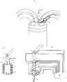
- This device consists of a closed heating element (10) with a fuel injector (1) and a solenoid valve (3), one Temperature sensor (5), a flow meter (6) and an inlet Valve which is electronic through a solenoid valve (4) or mechanically is regulated by an actuator (9) a control device (8) which is computerized regulated and controlled.
- the object of this invention is to provide a device which makes it possible to gasify a water / fuel mixture and direct it into the combustion chamber at high pressure Spark-ignited internal combustion engines of all kinds, such as gasoline engines, diesel engines, Wankel engine, and to transport turbines of all types.
- This The object is achieved in that the water-fuel mixture a solution is formed by an injection nozzle (1) in the so-called heating element (10) which has an electrical heating resistor (2) and injected and controlled by a control device (8) becomes.
- the fuel gasified in this heating element (10) now arrives by a solenoid valve (3) which closes or opens the heating element (10) to the inlet valve (4) of this device.
- This inlet valve (4) is connected to the control unit (8) of the internal combustion engine and is controlled by this so that the intake times and the intake quantities optimally tuned for the operation of the spark ignition internal combustion engine This is done using a flow meter (6) in the inlet channel (11).
- the inlet valve (4) can very well by an electronic computer-controlled solenoid valve (4) and also mechanically by a computer-controlled servomotor (9) open and close this inlet nozzle (12) which is part of the Device is effective in a split second.
- the spraying steel the gasified fuel is turned directly into the high-performance spark plug (7) with an increased spark. This will make for an optimum fuel consumption, explosion and combustion.
- the fuel mixture reaches the fuel injector through the fuel distributor (13) (1) .
- the fuel reaches the heating element by means of this (10) .
- This heating element (10) which is a closed Chamber with electrical heating resistors (diodes) (2) is provided Fuel injection nozzle (1) and a solenoid valve (3) a temperature sensor (5) which has the task of regulating the temperature so that it is at least 250 degrees Cellsius. Temperature and pressure by means of a control unit (8) to which the pressure sensor (14) is also connected is controlled and regulated. That in the heating element (10)
- the gasified fuel mixture now comes out of it by means of a solenoid valve (3) Chamber to the inlet channel (11) in which the flow meter (6) is located.
- the computer-controlled inlet valve (4) ensures the optimal amount of fuel through controlled inlet times. This intake amount will also still checked by means of a quantity sensor (6) in the inlet duct.
- the inlet valve can by an electronic computer controlled solenoid valve (4) and also mechanically by a computer-controlled servomotor (9). be operated.
- the gasified fuel-water mixture passes through the inlet nozzle now directly into the combustion chamber, where the spray jet is directed so that it hits the spark plug (7) directly spraying the gasified fuel is used for efficient combustion thanks to the high-performance candle (7). Through this system, a new generation of engines born. Without pollutants and an optimal one Consumption according to performance.
Landscapes
- Engineering & Computer Science (AREA)
- Chemical & Material Sciences (AREA)
- Combustion & Propulsion (AREA)
- Mechanical Engineering (AREA)
- General Engineering & Computer Science (AREA)
- Fuel-Injection Apparatus (AREA)
- Combustion Methods Of Internal-Combustion Engines (AREA)
- Output Control And Ontrol Of Special Type Engine (AREA)
- Combined Controls Of Internal Combustion Engines (AREA)
- Ignition Installations For Internal Combustion Engines (AREA)
Abstract
Description
- 1
- Kraftstoffeinspritzdüse
- 2
- Heizdioden, Heizwiderstände
- 3
- Magnetventil (Hochdruckventil)
- 4
- Einlaßventil
- 5
- Temperaturfühler
- 6
- Mengenmesser
- 7
- Hochleistungszündkerze
- 8
- Steuerelement (Computer)
- 9
- Stellmotor
- 10
- Heizelement
- 11
- Einlaßkanal
- 12
- Einlaßdüse
- 13
- Kraftstoffverteiler
- 14
- Druckmesser
Claims (5)
- Vorrichtung zur Vergasung eines Kraftstoff- Wassergemisches mit einem direktem Brennkammereinsprühsystem für gemisch - verdichtenden ,fremdzündenden Brennkraftmaschinen jeder Art. Mittels einer Kraftstoffeinspritzdüse (1) gelangt das Kraftstoff-Wassergemisch in das Heizelement (10 ) welches in den Wänden dieses Heizelementes (10) eingelasse Heizdioden (2) aufweist. Durch einen Temperaturfühler (5) wird die Temperatur kontrolliert wobei eine Mindesttemperatur von 250 Grad Cellius bis 1000 Grad Cellsius erreicht werden kann. Der Druck in diesem Heizelement (10) welche eine geschlossene Kammer ist wird mittels Druckfühler (14) kontrolliert. Das vergaste Kraftstoffgemisch gelangt nunmehr durch das Magnetventil (3) in den Einlaßkanal(11). In diesem befindet sich der Mengenmesser (6) welcher die Aufgabe hat für einen optimalen Verbrauch zu sorgen, gesteuert wird dieser über das Steuergerät (8). Durch das Einlaßventil (4) welches Computer gesteuert ist gelangt der vergaste Kraftstoff nun mehr mittels der Direkteinlaßdüse in den Brennraum mit direktem Sprühstrahl zur Zündkerze (7).Dieses EinlaßVentil(4) kann auch mechanisch betätigt werden und zwar mittels einem Stellmotor(9) der vom Steuergerät (8) aus kontrolliert wird und in der Lage ist in einem Bruchteil einer Sekunde zu öffnen oder zu schließen. Durch diese Einlaßzeiten wird der Kraftstoffverbrauch bestimmt.
- Vorrichtung nach Anspruch 1 , dadurch gekennzeichnet,daß das Heizelement(10) keine in den Wänden eingelassenen Heizwiderstände (2) vorweist sondern diese sich im Innenraum wie in der Zeichnung Fig.3 dargestellt befinden und einen Raster (Netz)(2) bilden.Die Dichte dieses Heizwiderstandes (2) hängt von der gewünschten sowie erforderlichen Heizleistung ab.
- Vorrichtung nach Anspruch 1 , dadurch gekennzeichnet,daß die Vorrichtung so abgestimmt wird, daß das verwenden von Kraftstoffen jeder Art ohne Wasser gewährleistet werden kann. Dafür wird das Heizelement (10) so geregelt das die Temperatur von 40 Grad Cellsius bis 200 Grad Cellsuis erreicht wird. Um diese Aufgabe bewältigen zu können wird dies mittels Temperaturfühler (5) und dem Steuergerät (8) geregelt.
- Vorrichtung nach Anspruch 1 , dadurch gekennzeichnet,daß die Vorrichtung aus Edelstahl, Stahl, Leichtmetall aus jeder Art von Metall- Legierungen wie Keramik sowie Celizium bestehen kann.
- Vorrichtung nach Anspruch 1 , dadurch gekennzeichnet, daß in dem Einlaßkanal (11) eine direkte Gasleitung angebracht ist,welche es ermöglicht den Betrieb ohne weitere Umbauten mit einem Natural Gas zu gewährleisten. Die dafür erforderlichen Daten werden in dem Steuergerät programmiert,durch den Mengenmesser(6) kann auch der Gasfluß kontrolliert werden und durch das Einlaßventil(4) wird für einen reibungslosen Betrieb einer jeder herkömmlichen Brennkraftmaschine jeder Bauart gesorgt.
Applications Claiming Priority (2)
| Application Number | Priority Date | Filing Date | Title |
|---|---|---|---|
| AT19652001 | 2001-12-14 | ||
| AT19652001 | 2001-12-14 |
Publications (3)
| Publication Number | Publication Date |
|---|---|
| EP1319816A2 true EP1319816A2 (de) | 2003-06-18 |
| EP1319816A3 EP1319816A3 (de) | 2003-07-09 |
| EP1319816B1 EP1319816B1 (de) | 2015-08-12 |
Family
ID=3689465
Family Applications (1)
| Application Number | Title | Priority Date | Filing Date |
|---|---|---|---|
| EP02450279.1A Expired - Lifetime EP1319816B1 (de) | 2001-12-14 | 2002-12-11 | HGIS-Direkteinsprühsystem |
Country Status (7)
| Country | Link |
|---|---|
| US (1) | US7013847B2 (de) |
| EP (1) | EP1319816B1 (de) |
| JP (1) | JP2005513318A (de) |
| CN (1) | CN100365254C (de) |
| AU (1) | AU2002360875A1 (de) |
| CA (1) | CA2470259A1 (de) |
| WO (1) | WO2003052244A1 (de) |
Cited By (2)
| Publication number | Priority date | Publication date | Assignee | Title |
|---|---|---|---|---|
| EP2014903A1 (de) * | 2007-03-23 | 2009-01-14 | LoNox Engine Company, Inc. | Wassereinspritzverbrennungsmotor |
| US7739985B2 (en) | 2006-03-23 | 2010-06-22 | Lonox Engine Company, Inc. | Internal combustion water injection engine |
Families Citing this family (11)
| Publication number | Priority date | Publication date | Assignee | Title |
|---|---|---|---|---|
| US7314033B2 (en) | 2004-11-18 | 2008-01-01 | Massachusetts Institute Of Technology | Fuel management system for variable ethanol octane enhancement of gasoline engines |
| US8353269B2 (en) * | 2004-11-18 | 2013-01-15 | Massachusetts Institute Of Technology | Spark ignition engine that uses intake port injection of alcohol to extend knock limits |
| US20080060627A1 (en) | 2004-11-18 | 2008-03-13 | Massachusetts Institute Of Technology | Optimized fuel management system for direct injection ethanol enhancement of gasoline engines |
| US8082735B2 (en) * | 2005-04-06 | 2011-12-27 | Massachusetts Institute Of Technology | Optimized fuel management system for direct injection ethanol enhancement of gasoline engines |
| RU2365779C2 (ru) * | 2005-03-18 | 2009-08-27 | Тойота Дзидося Кабусики Кайся | Двигатель с впрыском топлива двумя форсунками |
| US7640913B2 (en) * | 2006-03-08 | 2010-01-05 | Ethanol Boosting Systems, Llc | Single nozzle injection of gasoline and anti-knock fuel |
| WO2007106416A2 (en) * | 2006-03-10 | 2007-09-20 | Ethanol Boosting Systems, Llc. | Fuel tank system for direct ethanol injection octane boosted gasoline engine |
| WO2008014265A2 (en) * | 2006-07-24 | 2008-01-31 | Ethanol Boosting Systems, Llc | Single nozzle direct injection system for rapidly variable gasoline/anti-knock agent mixtures |
| US8522758B2 (en) | 2008-09-12 | 2013-09-03 | Ethanol Boosting Systems, Llc | Minimizing alcohol use in high efficiency alcohol boosted gasoline engines |
| JP2018035682A (ja) * | 2016-08-29 | 2018-03-08 | 真士 加藤 | エンジン |
| CN114717026B (zh) * | 2022-04-27 | 2023-02-07 | 西安交通大学 | 一种氢超临界水热燃烧反应装置及其使用方法 |
Family Cites Families (5)
| Publication number | Priority date | Publication date | Assignee | Title |
|---|---|---|---|---|
| AT385564B (de) * | 1985-12-02 | 1988-04-25 | Auer Gerhard | Einrichtung zur verdampfung von kraftstoff |
| DE3734346A1 (de) * | 1987-10-10 | 1989-04-27 | Kernforschungsanlage Juelich | Verfahren und zylinderkopf zur zufuehrung von kraftstoff in einen kolbenmotor |
| US5582139A (en) | 1995-02-08 | 1996-12-10 | Feuerman; Arnold I. | Fuel injector for a gaseous fuel supply |
| US6010544A (en) * | 1997-12-18 | 2000-01-04 | Quantum Energy Technologies | Supercritical water fuel composition and combustion system |
| US6487994B2 (en) * | 1999-07-23 | 2002-12-03 | Supercritical Combustion Corporation | Sub-critical water-fuel composition and combustion system |
-
2002
- 2002-12-11 AU AU2002360875A patent/AU2002360875A1/en not_active Abandoned
- 2002-12-11 JP JP2003553105A patent/JP2005513318A/ja active Pending
- 2002-12-11 US US10/499,371 patent/US7013847B2/en not_active Expired - Lifetime
- 2002-12-11 CN CNB028249690A patent/CN100365254C/zh not_active Expired - Fee Related
- 2002-12-11 CA CA002470259A patent/CA2470259A1/en not_active Abandoned
- 2002-12-11 WO PCT/AT2002/000346 patent/WO2003052244A1/de not_active Ceased
- 2002-12-11 EP EP02450279.1A patent/EP1319816B1/de not_active Expired - Lifetime
Cited By (4)
| Publication number | Priority date | Publication date | Assignee | Title |
|---|---|---|---|---|
| US7739985B2 (en) | 2006-03-23 | 2010-06-22 | Lonox Engine Company, Inc. | Internal combustion water injection engine |
| US7798119B2 (en) | 2006-03-23 | 2010-09-21 | Lonox Engine Company, Inc. | Internal combustion water injection engine |
| US7938103B2 (en) | 2006-03-23 | 2011-05-10 | Lonox Engine Company, Inc. | Internal combustion water injection engine |
| EP2014903A1 (de) * | 2007-03-23 | 2009-01-14 | LoNox Engine Company, Inc. | Wassereinspritzverbrennungsmotor |
Also Published As
| Publication number | Publication date |
|---|---|
| CA2470259A1 (en) | 2003-06-26 |
| EP1319816B1 (de) | 2015-08-12 |
| CN100365254C (zh) | 2008-01-30 |
| AU2002360875A1 (en) | 2003-06-30 |
| EP1319816A3 (de) | 2003-07-09 |
| US20050066575A1 (en) | 2005-03-31 |
| JP2005513318A (ja) | 2005-05-12 |
| WO2003052244A1 (de) | 2003-06-26 |
| US7013847B2 (en) | 2006-03-21 |
| CN1604990A (zh) | 2005-04-06 |
Similar Documents
| Publication | Publication Date | Title |
|---|---|---|
| EP1319816A2 (de) | HGIS-Direkteinsprühsystem | |
| WO2010022416A1 (de) | Verbrennungsturbine mit diskontinuierlicher verbrennung | |
| DE19751996A1 (de) | Kraftstoffheizvorrichtung für Schwerölmotoren | |
| DE1776012A1 (de) | Kraftstoff-Drosselsystem fuer eine Verbrennungskraftmaschine | |
| DE69114490T2 (de) | System zur steuerung der abgas-temperatur eines katalytisch gereinigten verbrennungsmotors. | |
| EP0124693A1 (de) | Verfahren zur Einbringung eines flüssigen Mediums in den Arbeitsraum einer Verbrennungskraftmaschine | |
| US4342287A (en) | Method and apparatus for utilizing alcohol as fuel for internal combustion engine | |
| WO2014060071A1 (de) | Verfahren zum betreiben eines hubkolben-verbrennungsmotors | |
| DE19754354C1 (de) | Diesel-Gasmotor | |
| DE3504699A1 (de) | Wasserbeimischung zum dieselkraftstoff bei dieselmotoren kurz vor der einspritzpumpe | |
| DE3307414C2 (de) | Vorrichtung zum Zuführen von Kraftstoff | |
| DE2536432A1 (de) | Kaltstart- und warmlaufeinrichtung | |
| ES400553A1 (es) | Sistema de alimentacion mixta gas-oil-gas de petroleo li- quido en motores diesel. | |
| DE102017110668A1 (de) | Verfahren zum Betrieb einer gasbetriebenen Brennkraftmaschine und Einrichtung hierzu | |
| DE19706959A1 (de) | Zündverfahren für einen Hubkolben-Gasmotor | |
| DE69418707T2 (de) | Katalysevorrichtung für eine Brennkraftmaschine | |
| DE4327149C2 (de) | Vorrichtung zur Zuführung von Verbrennungsluft und Kraftstoff in eine Ansaugleitung einer Brennkraftmaschine | |
| DE615102C (de) | Einrichtung zur Speisung und Zuendung von Brennkraftmaschinen mit Leicht- und Schwerkraftstoff | |
| DE902900C (de) | Verfahren und Vorrichtung zur Vergasung von festen Brennstoffen, insbesondere in Fahrzeuggaserzeugern | |
| DE514776C (de) | Gemischverdichtende Brennkraftmaschine mit Fremdzuendung | |
| DE551200C (de) | Luftverdichtende Brennkraftmaschine mit einer Vorkammer | |
| US931389A (en) | Internal-combustion engine. | |
| EP0299132A1 (de) | Einrichtung zur Verdampfung einer Kraftstoff-Wasseremulsion für Brennkraftmaschine | |
| AT82521B (de) | Verfahren und Vorrichtung zur Erzeugung von brennbaren Gasen oder Dämpfen aus flüssigen Brennstoffen. | |
| DE102005023217A1 (de) | Abgaswertgesteuerte Kraftstoffmischanlage für ein mit Pflanzenöl und Diesel zu betreibendes Dieselantriebsaggregat |
Legal Events
| Date | Code | Title | Description |
|---|---|---|---|
| PUAI | Public reference made under article 153(3) epc to a published international application that has entered the european phase |
Free format text: ORIGINAL CODE: 0009012 |
|
| PUAL | Search report despatched |
Free format text: ORIGINAL CODE: 0009013 |
|
| AK | Designated contracting states |
Designated state(s): AT BE BG CH CY CZ DE DK EE ES FI FR GB GR IE IT LI LU MC NL PT SE SI SK TR |
|
| AX | Request for extension of the european patent |
Extension state: AL LT LV MK RO |
|
| AK | Designated contracting states |
Designated state(s): AT BE BG CH CY CZ DE DK EE ES FI FR GB GR IE IT LI LU MC NL PT SE SI SK TR |
|
| AX | Request for extension of the european patent |
Extension state: AL LT LV MK RO |
|
| RIC1 | Information provided on ipc code assigned before grant |
Ipc: 7F 02M 25/022 B Ipc: 7F 02B 47/02 A |
|
| 17P | Request for examination filed |
Effective date: 20031205 |
|
| AKX | Designation fees paid |
Designated state(s): AT BE BG CH CY CZ DE DK EE ES FI FR GB GR IE IT LI LU MC NL PT SE SI SK TR |
|
| 17Q | First examination report despatched |
Effective date: 20041208 |
|
| GRAP | Despatch of communication of intention to grant a patent |
Free format text: ORIGINAL CODE: EPIDOSNIGR1 |
|
| INTG | Intention to grant announced |
Effective date: 20140221 |
|
| GRAS | Grant fee paid |
Free format text: ORIGINAL CODE: EPIDOSNIGR3 |
|
| GRAA | (expected) grant |
Free format text: ORIGINAL CODE: 0009210 |
|
| AK | Designated contracting states |
Kind code of ref document: B1 Designated state(s): AT BE BG CH CY CZ DE DK EE ES FI FR GB GR IE IT LI LU MC NL PT SE SI SK TR |
|
| REG | Reference to a national code |
Ref country code: GB Ref legal event code: FG4D Free format text: NOT ENGLISH |
|
| REG | Reference to a national code |
Ref country code: CH Ref legal event code: EP |
|
| REG | Reference to a national code |
Ref country code: AT Ref legal event code: REF Ref document number: 742367 Country of ref document: AT Kind code of ref document: T Effective date: 20150815 |
|
| REG | Reference to a national code |
Ref country code: IE Ref legal event code: FG4D Free format text: LANGUAGE OF EP DOCUMENT: GERMAN |
|
| REG | Reference to a national code |
Ref country code: DE Ref legal event code: R096 Ref document number: 50216071 Country of ref document: DE |
|
| REG | Reference to a national code |
Ref country code: NL Ref legal event code: MP Effective date: 20150812 |
|
| PG25 | Lapsed in a contracting state [announced via postgrant information from national office to epo] |
Ref country code: FI Free format text: LAPSE BECAUSE OF FAILURE TO SUBMIT A TRANSLATION OF THE DESCRIPTION OR TO PAY THE FEE WITHIN THE PRESCRIBED TIME-LIMIT Effective date: 20150812 Ref country code: GR Free format text: LAPSE BECAUSE OF FAILURE TO SUBMIT A TRANSLATION OF THE DESCRIPTION OR TO PAY THE FEE WITHIN THE PRESCRIBED TIME-LIMIT Effective date: 20151113 |
|
| PG25 | Lapsed in a contracting state [announced via postgrant information from national office to epo] |
Ref country code: SE Free format text: LAPSE BECAUSE OF FAILURE TO SUBMIT A TRANSLATION OF THE DESCRIPTION OR TO PAY THE FEE WITHIN THE PRESCRIBED TIME-LIMIT Effective date: 20150812 Ref country code: PT Free format text: LAPSE BECAUSE OF FAILURE TO SUBMIT A TRANSLATION OF THE DESCRIPTION OR TO PAY THE FEE WITHIN THE PRESCRIBED TIME-LIMIT Effective date: 20151214 Ref country code: ES Free format text: LAPSE BECAUSE OF FAILURE TO SUBMIT A TRANSLATION OF THE DESCRIPTION OR TO PAY THE FEE WITHIN THE PRESCRIBED TIME-LIMIT Effective date: 20150812 |
|
| PG25 | Lapsed in a contracting state [announced via postgrant information from national office to epo] |
Ref country code: NL Free format text: LAPSE BECAUSE OF FAILURE TO SUBMIT A TRANSLATION OF THE DESCRIPTION OR TO PAY THE FEE WITHIN THE PRESCRIBED TIME-LIMIT Effective date: 20150812 |
|
| PG25 | Lapsed in a contracting state [announced via postgrant information from national office to epo] |
Ref country code: IT Free format text: LAPSE BECAUSE OF FAILURE TO SUBMIT A TRANSLATION OF THE DESCRIPTION OR TO PAY THE FEE WITHIN THE PRESCRIBED TIME-LIMIT Effective date: 20150812 Ref country code: SK Free format text: LAPSE BECAUSE OF FAILURE TO SUBMIT A TRANSLATION OF THE DESCRIPTION OR TO PAY THE FEE WITHIN THE PRESCRIBED TIME-LIMIT Effective date: 20150812 Ref country code: DK Free format text: LAPSE BECAUSE OF FAILURE TO SUBMIT A TRANSLATION OF THE DESCRIPTION OR TO PAY THE FEE WITHIN THE PRESCRIBED TIME-LIMIT Effective date: 20150812 Ref country code: CZ Free format text: LAPSE BECAUSE OF FAILURE TO SUBMIT A TRANSLATION OF THE DESCRIPTION OR TO PAY THE FEE WITHIN THE PRESCRIBED TIME-LIMIT Effective date: 20150812 Ref country code: EE Free format text: LAPSE BECAUSE OF FAILURE TO SUBMIT A TRANSLATION OF THE DESCRIPTION OR TO PAY THE FEE WITHIN THE PRESCRIBED TIME-LIMIT Effective date: 20150812 |
|
| REG | Reference to a national code |
Ref country code: DE Ref legal event code: R097 Ref document number: 50216071 Country of ref document: DE |
|
| PG25 | Lapsed in a contracting state [announced via postgrant information from national office to epo] |
Ref country code: BE Free format text: LAPSE BECAUSE OF NON-PAYMENT OF DUE FEES Effective date: 20151231 |
|
| PLBE | No opposition filed within time limit |
Free format text: ORIGINAL CODE: 0009261 |
|
| STAA | Information on the status of an ep patent application or granted ep patent |
Free format text: STATUS: NO OPPOSITION FILED WITHIN TIME LIMIT |
|
| 26N | No opposition filed |
Effective date: 20160513 |
|
| PG25 | Lapsed in a contracting state [announced via postgrant information from national office to epo] |
Ref country code: LU Free format text: LAPSE BECAUSE OF FAILURE TO SUBMIT A TRANSLATION OF THE DESCRIPTION OR TO PAY THE FEE WITHIN THE PRESCRIBED TIME-LIMIT Effective date: 20151211 Ref country code: MC Free format text: LAPSE BECAUSE OF FAILURE TO SUBMIT A TRANSLATION OF THE DESCRIPTION OR TO PAY THE FEE WITHIN THE PRESCRIBED TIME-LIMIT Effective date: 20150812 |
|
| REG | Reference to a national code |
Ref country code: CH Ref legal event code: PL |
|
| GBPC | Gb: european patent ceased through non-payment of renewal fee |
Effective date: 20151211 |
|
| PG25 | Lapsed in a contracting state [announced via postgrant information from national office to epo] |
Ref country code: SI Free format text: LAPSE BECAUSE OF FAILURE TO SUBMIT A TRANSLATION OF THE DESCRIPTION OR TO PAY THE FEE WITHIN THE PRESCRIBED TIME-LIMIT Effective date: 20150812 |
|
| REG | Reference to a national code |
Ref country code: IE Ref legal event code: MM4A |
|
| REG | Reference to a national code |
Ref country code: FR Ref legal event code: ST Effective date: 20160831 |
|
| PG25 | Lapsed in a contracting state [announced via postgrant information from national office to epo] |
Ref country code: GB Free format text: LAPSE BECAUSE OF NON-PAYMENT OF DUE FEES Effective date: 20151211 Ref country code: IE Free format text: LAPSE BECAUSE OF NON-PAYMENT OF DUE FEES Effective date: 20151211 Ref country code: CH Free format text: LAPSE BECAUSE OF NON-PAYMENT OF DUE FEES Effective date: 20151231 Ref country code: LI Free format text: LAPSE BECAUSE OF NON-PAYMENT OF DUE FEES Effective date: 20151231 |
|
| PG25 | Lapsed in a contracting state [announced via postgrant information from national office to epo] |
Ref country code: FR Free format text: LAPSE BECAUSE OF NON-PAYMENT OF DUE FEES Effective date: 20151231 |
|
| REG | Reference to a national code |
Ref country code: AT Ref legal event code: MM01 Ref document number: 742367 Country of ref document: AT Kind code of ref document: T Effective date: 20151211 |
|
| PG25 | Lapsed in a contracting state [announced via postgrant information from national office to epo] |
Ref country code: AT Free format text: LAPSE BECAUSE OF NON-PAYMENT OF DUE FEES Effective date: 20151211 Ref country code: BG Free format text: LAPSE BECAUSE OF FAILURE TO SUBMIT A TRANSLATION OF THE DESCRIPTION OR TO PAY THE FEE WITHIN THE PRESCRIBED TIME-LIMIT Effective date: 20150812 |
|
| PG25 | Lapsed in a contracting state [announced via postgrant information from national office to epo] |
Ref country code: CY Free format text: LAPSE BECAUSE OF FAILURE TO SUBMIT A TRANSLATION OF THE DESCRIPTION OR TO PAY THE FEE WITHIN THE PRESCRIBED TIME-LIMIT Effective date: 20150812 |
|
| PG25 | Lapsed in a contracting state [announced via postgrant information from national office to epo] |
Ref country code: TR Free format text: LAPSE BECAUSE OF FAILURE TO SUBMIT A TRANSLATION OF THE DESCRIPTION OR TO PAY THE FEE WITHIN THE PRESCRIBED TIME-LIMIT Effective date: 20150812 |
|
| PGFP | Annual fee paid to national office [announced via postgrant information from national office to epo] |
Ref country code: DE Payment date: 20200224 Year of fee payment: 18 |
|
| REG | Reference to a national code |
Ref country code: DE Ref legal event code: R119 Ref document number: 50216071 Country of ref document: DE |
|
| PG25 | Lapsed in a contracting state [announced via postgrant information from national office to epo] |
Ref country code: DE Free format text: LAPSE BECAUSE OF NON-PAYMENT OF DUE FEES Effective date: 20210701 |