EP2014903A1 - Wassereinspritzverbrennungsmotor - Google Patents
Wassereinspritzverbrennungsmotor Download PDFInfo
- Publication number
- EP2014903A1 EP2014903A1 EP08005402A EP08005402A EP2014903A1 EP 2014903 A1 EP2014903 A1 EP 2014903A1 EP 08005402 A EP08005402 A EP 08005402A EP 08005402 A EP08005402 A EP 08005402A EP 2014903 A1 EP2014903 A1 EP 2014903A1
- Authority
- EP
- European Patent Office
- Prior art keywords
- water
- internal combustion
- combustion engine
- fuel
- recited
- Prior art date
- Legal status (The legal status is an assumption and is not a legal conclusion. Google has not performed a legal analysis and makes no representation as to the accuracy of the status listed.)
- Withdrawn
Links
Images


Classifications
-
- F—MECHANICAL ENGINEERING; LIGHTING; HEATING; WEAPONS; BLASTING
- F02—COMBUSTION ENGINES; HOT-GAS OR COMBUSTION-PRODUCT ENGINE PLANTS
- F02M—SUPPLYING COMBUSTION ENGINES IN GENERAL WITH COMBUSTIBLE MIXTURES OR CONSTITUENTS THEREOF
- F02M25/00—Engine-pertinent apparatus for adding non-fuel substances or small quantities of secondary fuel to combustion-air, main fuel or fuel-air mixture
- F02M25/022—Adding fuel and water emulsion, water or steam
- F02M25/0228—Adding fuel and water emulsion
-
- F—MECHANICAL ENGINEERING; LIGHTING; HEATING; WEAPONS; BLASTING
- F02—COMBUSTION ENGINES; HOT-GAS OR COMBUSTION-PRODUCT ENGINE PLANTS
- F02M—SUPPLYING COMBUSTION ENGINES IN GENERAL WITH COMBUSTIBLE MIXTURES OR CONSTITUENTS THEREOF
- F02M25/00—Engine-pertinent apparatus for adding non-fuel substances or small quantities of secondary fuel to combustion-air, main fuel or fuel-air mixture
- F02M25/022—Adding fuel and water emulsion, water or steam
- F02M25/0221—Details of the water supply system, e.g. pumps or arrangement of valves
- F02M25/0225—Water atomisers or mixers, e.g. using ultrasonic waves
-
- F—MECHANICAL ENGINEERING; LIGHTING; HEATING; WEAPONS; BLASTING
- F02—COMBUSTION ENGINES; HOT-GAS OR COMBUSTION-PRODUCT ENGINE PLANTS
- F02M—SUPPLYING COMBUSTION ENGINES IN GENERAL WITH COMBUSTIBLE MIXTURES OR CONSTITUENTS THEREOF
- F02M25/00—Engine-pertinent apparatus for adding non-fuel substances or small quantities of secondary fuel to combustion-air, main fuel or fuel-air mixture
- F02M25/022—Adding fuel and water emulsion, water or steam
- F02M25/025—Adding water
- F02M25/03—Adding water into the cylinder or the pre-combustion chamber
-
- Y—GENERAL TAGGING OF NEW TECHNOLOGICAL DEVELOPMENTS; GENERAL TAGGING OF CROSS-SECTIONAL TECHNOLOGIES SPANNING OVER SEVERAL SECTIONS OF THE IPC; TECHNICAL SUBJECTS COVERED BY FORMER USPC CROSS-REFERENCE ART COLLECTIONS [XRACs] AND DIGESTS
- Y02—TECHNOLOGIES OR APPLICATIONS FOR MITIGATION OR ADAPTATION AGAINST CLIMATE CHANGE
- Y02T—CLIMATE CHANGE MITIGATION TECHNOLOGIES RELATED TO TRANSPORTATION
- Y02T10/00—Road transport of goods or passengers
- Y02T10/10—Internal combustion engine [ICE] based vehicles
- Y02T10/12—Improving ICE efficiencies
Definitions
- the apparatus and system as described below relates to a water injection-type system adapted to inject water droplets in a very fine mist into a combustion chamber.
- the apparatus is a rotary piston engine, and in one form, a static constant speed engine.
- the teachings herein can be applied to other types of engines, such as static variable speed, mobile platform constant speed, and mobile platform variable speed.
- the internal combustion engine system having water injected into the engine for reducing NOx gases.
- the internal combustion engine system comprises an engine casing having an interior cylinder having a cylindrical wall portion.
- the piston operatively configured to be repositioned within the interior cylinder in an oscillating manner and further being connected to a crankshaft.
- An ignition member is provided with anode and cathode portions optimally configured to provide an ignition spark within the interior cylinder.
- a fuel air input valve and an exhaust valve are configured to insert a fuel air mixture into the interior cylinder and remove combusted gas respectively.
- the piston, interior cylinder and fuel air input and exhaust valves have relative positions so the piston has a downward fuel air intake stroke, an outward fuel air compression stroke, a downward power stroke, and an upward exhaust stroke.
- a nozzle member having a main body and a nozzle tip region in communication with the interior chamber.
- the nozzle member comprises an actuator to alternatively allow communication of the nozzle tip region to a high-pressure water source and to discontinue communication of the nozzle tip region to the high-pressure water source.
- the nozzle further has a spray cone adjustment system where the cross-sectional open area of the nozzle member at the nozzle tip region is repositioned up from a narrower orientation to disburse a narrower apical angle of a water disbursement cone to a wider orientation to disburse a wider apical angle of a water disbursement cone.
- a high-pressure pump is in communication with a high-pressure source to increase the pressure thereof prior to the transfer of water to the nozzle member for dispersion within the interior cylinder.
- a logic controller having a pressure sensor of the high-pressure source where the logic controller is configured to operate the high-pressure pump to increase the pressure of the high-pressure source.
- the logic controller is operatively configured to control the actuator of the nozzle member to allow communication of the high-pressure source and the interior chamber.
- the logic controller is further configured to inject a spray cone mist of water during the upward fuel air compression stroke at a first apical cone angle and inject a spray cone mist of water at the transition from the upward fuel air compression stroke to the downward power stroke at a second apical column angle which is greater than the first apical cone angle where the first and second apical cone angles, with respect to the location of the piston, are such that the spray cone mast does not directly contact the cylindrical wall portion of the interior chamber.
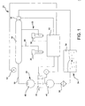
- a schematic system 20 In general, the system comprises a nozzle or nozzle assembly 22, a water reservoir 24, a water distribution system 26, and as shown in Fig. 2 , an internal combustion engine 25.
- the nozzle assembly 22 in one form comprises the first and second nozzles 30 and 32.
- any number of nozzles can be utilized. The nozzles will be described further herein with reference to Figs. 5 and 6 .
- the water reservoir 24 in general comprises a water tank 34.
- the water tank 34 holds the water supply 36 which can be from a common source of water or condensed by some water condensation means.
- a water filter 38 can be utilized. Of course, the water filter 38 can be used prior to the insertion of the water into the tank 36.
- the water distribution system 26 in one form comprises a low pressure water pump 40 which is operatively configured to be controlled by the logic controller such as a programmable logic controller (PLC) 42.
- PLC programmable logic controller
- the PLC 42 will be described further herein, and of course other logic controllers can be utilized, such as (in some forms) a purely mechanical control system.
- the PLC controls the various mechanisms in the system 20 such as the flow control valve 44.
- the low pressure water pump 40 provides a sufficient amount of pressure to the high-pressure pump 46 which increases the pressure of the fluid for injection into the interior cylinder 61 as shown in Figs. 2 --4 and discussed further herein.
- the high-pressure fluid passes through the manifold 48 where the line 50 has the pressure sensor 52 in communication therewith, which feeds the signal back to the PLC 42.
- a pressure reduction valve 54 which operates as a general pressure limiter can be in communication with the manifold 48 to ensure that the pressure therein does not exceed predetermined limits.
- the high-pressure water is fed to the nozzles 30 and 32, and as noted above, can be fed to a single nozzle for a single chamber engine, or possibly fed to twelve nozzles for a twelve-cylinder engine such as the V-12.
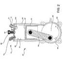
- the engine 25 is of a common design.
- a cylinder bore 60 with an interior cylinder 61 having an interior cylindrical wall 69 configured to house a piston 62 having an upper surface 67 therein.
- the piston is attached to a bar 64 which in turn is attached to a crankshaft-like mechanism 66.
- the crankshaft is housed within a crank case 68.
- the valve system 70 is utilized where the emission valve 72 opens to allow the fuel air mixture to enter the interior cylinder 61.
- the exhaust valve 74 is configured to open to allow the exhausted gas within the chamber to be expelled during the exhaust stroke.
- internal combustion engines are well known, and various relevant patents such as 1,986,630 and 6,202,613 are hereby incorporated by references.
- an ignition member 71 is positioned in the upper portion of the cylinder at the cylinder head 63.
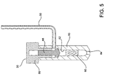
- the ignition member 71 is a conventional spark plug and is described herein with reference to Fig. 6 .
- the nozzle member 30' is operatively configured to be fitted into a conventional spark plug head mount opening in the cylinder head for a retrofit to an existing engine such that the nozzle member 30' not only supplies the ignition spark to ignite the fuel air mixture, but further provides a system for injecting water into the interior cylinder 61. This embodiment will be described further herein in greater detail.
- the nozzle member 30 has a nozzle body 80 defining a central chamber 82 which has a nozzle tip region 84.
- an actuator 86 is utilized where a valve member such as the plunger 88 is schematically shown that is activated by the actuator, such as a piezoelectric actuator device.
- the water input line 90 is configured to communicate with the interior chamber 82, and in one form, a check valve 92 allows for a one-way flow of water downward into the cylinder of the engine.
- the line 90 can provide a fuel air mixture from the output line/port 167 of the mixing chamber in Fig. 11 .
- the nozzle tip region 84 can be of a multitude of designs, where as described herein with reference to Figs. 7 and 8 , a variation of the design can disperse the frustoconical dispersion of water into the interior cylinder 61 of the engine (see Fig. 2 ) at a variety of apical angles.
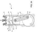
- Fig. 3A it can be seen that the rotation of the crank shaft 66 is counterclockwise, as indicated by the arrow 100. Therefore, the piston 62 is in a downward stroke within the interior cylinder 61, and in one form, the valve member 72 is open allowing the fuel air mixture 102 to enter the interior cylinder 61.
- the nozzle member 30 has the valve member 88 in an open orientation, and in one form, the PLC 42 instructs the valve member 88 to open such that water from the manifold 48 is dispersed through the valve to the water injection line 90 (see Figs. 1 and 5 ) into a frustoconical spray cone 104 as shown in Fig. 3A .
- a high-pressure system where the manifold 48 allows for a simpler design of the nozzle 30 where the nozzle has a high-pressure control valve 88. The moment the valve is open, the water is dispersed at full pressure and the water entering is entirely dependent upon the time that the valve is open. It should further be noted that having the initial low pressure pump 40 provides a sufficient positive suction head (NPSH) for the intake valve of the high-pressure pump 46. By having the valve and the nozzle, it is desirable to mitigate the amount of leakage of water. It is easier to build the flow control valve 44 for low pressure, and the net static hydro pressure is sufficiently high from the low pressure pump 40. The high-pressure pump should be upstream of the flow control valve 44, otherwise the high-pressure pump could damage the flow control valve.
- NPSH positive suction head
- Fig. 2 there is an intake stroke and the valve 72 is open.
- the nozzle 30 is closed, and fluid is not injected into the interior cylinder 61.
- the piston 62 is shown traveling in an downward position. In one form, before 15° before top dead center (TDC), water injection starts and the water injection is completed before ignition is initiated.
- TDC top dead center
- the dimension indicated generally at 110 indicates a vertical distance from the water spray 114 to the upper surface 67 of the piston 62.
- the dimension 112 indicates a general distance between the outer area of the frustoconical water mist 14 and the interior surface 69 of the cylinder 60, which is a function of the actual geometry of the piston.
- the diameter of the lower perimeter portion 75 of the outer frustoconical area 73 is less than 3 ⁇ 4 of the diameter of the interior cylinder 61.
- the outer frustoconical area 73 of the cone should generally be such that the column of water is not dispersed to the cylindrical wall 69.
- the gap indicated at 112 can be between 1/6 to 5/12 the diameter of the cylinder 61 and the gap 110 can be for example zero to 1 ⁇ 2 the height of the cone 104.
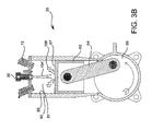
- Fig. 3B shows another embodiment where the crankshaft 66 advanced such that the piston member 62 is directed upwardly.
- the emission valve 72 is closed as the pressure within the interior cylinder 61 increases.
- the water stream 104' is dispersed on the upper surface 67 of the piston 62, and the water droplets 106 bounce and disperse outwardly.
- the cylinder is repositioned upwardly at a relatively high velocity, and the timing of the water droplets 106 is such that they should not impact the interior walls 69 of the cylinder 60.
- the ignition member 71 has induced a spark within the interior cylinder 61.
- water is continue to be disbursed within the interior cylinder 61, and the water column indicated at 104" continues to be disbursed such that the dimension 110' and 112' are such that the cone is a wider angle.
- the cone angle can be wider by way of utilizing a variable cone dispersion nozzle which is described further herein.
- the post-injection occurs approximately no after combustion for a duration during the piston stroke to bottom center.
- the post-injection helps to further cool the temperature within the interior chamber 61.
- the combustion temperature rate is not affected but the temperature is lower.
- the formation of nefarious greenhouse gases such as NO and CO are problematic when the temperature within the cylinders in a combustion engine is too high.
- the incylinder temperature should be lowered approximately to below 1200° Celsius which is both below threshold where NO and CO compounds are created.
- the water pressure can be between 1000 to 15,000 psi to create the atomized mist.
- the nozzle 30 can be very similar to a diesel fuel injection nozzle. With a diesel cycle engine, fuel is injected at high-pressure , and in this case the water droplets are injected at high pressure. It can be seen in Fig. 4 that the cone angle outer region 73.
- the engine 25 may also be a two-stroke engine utilizing the water injection cone 104. Of course, in such an orientation the valves would not be necessary.
- a preferred form of an engine is a high horsepower engine such as a 400 to 5000 hp engine.
- static constant speed engine such as stationary rotational driver equipment applications is one desired environment for the present invention.
- the water droplet size With regard to the water droplet size, present analysis indicates that one preferred range is 50-100 microns for the water droplets and a broader range of 50 to 250 microns for the water droplet diameter size.
- the amount of water may be between 10 to 20% on a molar basis of the amount of gas or fuel injected. Of course this range can vary depending on various factors.
- the frustoconical shaped water droplet dispersion cone 104 A few of the aspects of the cone dispersion of water include the timing of the injection the cone geometry, the actual water mass that is injected into the chamber, and the size of the water droplets. In one form a 30° cone apical angle is considered to be a desirable range, plus or minus 10°.
- the cone should be constructed so the water droplets do not hit the side wall of the interior chamber 61 which would compromise the lubricity of the oil film positioned thereon to lubricate the piston's movement. Therefore, the water injection nozzle should be positioned in the upper portion of the piston chamber and directed the water coned thereupon downwardly away from the cylindrical interior walls.
- FIG. 7 there is shown another nozzle embodiment 30" which is similar to the previous embodiments except for the spray cone adjustment system 130.
- the annular ring member 132 is operatively configured to form a narrow passageway 134 for a narrower cone dispersion and further can be repositioned to a wider orientation such as that as shown in Fig. 8 as indicated by the dimension 134' for a broader cone distribution.
- this embodiment could be combined with the nozzle embodiment as shown in Fig. 6 to have ignition member further positioned on the main body 80" of Figs. 7 and 8 .
- the outer area of the cone 71 on Fig. 3A is of a narrower apical angle than the cone 71' in Fig. 4 .
- This can be accomplished by using an embodiment of Fig. 7 and 8 as well as Figs. 14-19 .
- the water jet is used partially to cool the igniting electrodes, thereby extending their operating life.
- a second nozzle member 30' has many similar components to the previous nozzle member 30 shown in Fig. 5 ; however, the ignition member 71' is positioned within the main body 80'. The other components of the nozzle member 30' are similar to the previous nozzle member 30 as shown in Fig. 5 .
- the pressure control valve 88 and the actuator 86 are of a very similar design.
- One advantage of having the ignition member 71' as part of the nozzle body 80 is that the nozzle 30' can be easily retrofitted to an existing spark plug hole in the upper portion of a cylinder head of an engine.
- the lower cylindrical surface indicated at 120 can be, for example, a threaded male surface of conventional thread pitch to be similar to a conventional spark plug.
- the electrode portion 122 can have an insulating sheath 124 such that the electrode 122 is in communication with a charged particle source that can be of a conventional design.
- the anode member 125 is positioned at a predefined distance from the cathode extension 127 to create a spark within the interior cylinder for ignition of the air fuel mixture therein.
- the members 125 and 127 are positioned above the lower lip 128 of the main body 80' so the water fluid ejected therefrom does not interfere with the ignition of the ignition member 71'.
- Fig. 9 shows another embodiment where downstream of the accumulator 144 is a water-cooling device 145 that is interposed between the accumulator 144 and a pump 146.
- the water-cooling device reduces the temperature of the water stream to above a freezing point. In one form, the temperature of the water should be between 1° and 35° C approximately.
- the cooler water helps the injected fluid cooler water absorb more energy before it evaporates to reduce the temperature of the combustion.
- Fig. 10 shows another variation of the system where a water cooling agent 145' is positioned downstream of the pump 46'. As discussed further herein, reducing the water temperature further aids in cooling the interior cylinder temperature to prevent the production of NOxious gases.
- an oxygen injection system can be utilized. This system option enables the dissolution of pure oxygen into the water source.
- the oxygen supply (from commercially available equipment) would be placed upstream of the pump, or fed directly into the accumulator, to enrich the water stream. This additional oxygen will act as catalyst for the combustion process during ignition, mitigating the flame retardation effects of the water droplets.
- the mist injector 160 emits a mist-like cone 162 into a first ionization chamber 164. Within the ionization chamber, the various particles are charged either positively or negatively. For purposes of this discussion, we will assume that the water droplets are charged positively and passed to the mixing chamber 166. A similar process occurs with the fuel injection nozzle 168 where a fuel-injected gaseous mist 170 is, for example, negatively charged by the negative ion and the mist 170 is passed to the mixing chamber 166.
- a particle mixture 170 where a positively charged water droplet 172 and a negatively charged fuel gas174 is positioned therearound.
- a positively charged water droplet 172 and a negatively charged fuel gas174 is positioned therearound.
- the anode and cathode of the water and fuel chambers can be switched to change the charge of each substance.
- the mixture in the mixing chamber 166 is passed through line 167 and directed to the internal combustion chamber in a similar manner as described above, but instead of separating the dispersion of fluid within the chamber between the fuel and the water, the water fuel mixture is injected therein.
- this combination can be utilized with the previously mentioned combination such that pure water is injected in the latter portion of the upward stroke. Further, pure fuel can be injected previously; this form only supplements the process, or alternately, this form of fuel injection can be used exclusively. Of course, the water injection in the downward stroke would be executed with only water and not a fuel water droplet mixture.
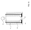
- FIG. 12 where there is a cross-sectional view of an injection nozzle 30'" where the fuel air mixture and water mist shares a common orifice 200.
- the injection nozzle can be adapted to disperse fuel as well as water at different intervals where that the injection nozzle 30'" can be retrofitted to an existing engine by replacing one of the valves, namely the fuel intake valve.
- the schematic cam 202 is utilized as the timing device to inject the water where an internal valve-like system is controlled by the rotational position, and basically the orientation of the piston.
- the member 202 can be an actuator such as a piezoelectric actuator similar to the actuator 86 described above.
- Directly attached to the engine cam shaft has advantages where the valve action directly correlates to the orientation of the piston and the timing of the firing of the spark plug.
- the internal water mist nozzle 204 will be in communication with the orifice port and be ejecting water therefrom in one form at approximately 30° from top dead-center of the piston, up to a maximum in one form of the spark ignition. Thereafter, the water mist nozzle is again in communication with the orifice ejecting water for the second phase in the downward stroke of the piston to cool the gas therein to prevent Noxious gases from forming.
- mist nozzle 204 rises upwardly where the air exhaust valve opens to exhaust the combusted gas through the annular channel 206.
- the nozzle member 30'" could replace the fuel injection valve and the fuel air mixture will pass through the channel 206.
- the injection valve In the downward stroke in a four-stroke cycle, the injection valve will adjust to place the fuel injection chamber in communication with the piston chamber to allow fuel to be injected therein.
- the water injection portion of the nozzle On the upward stroke, the water injection portion of the nozzle is now in communication with the orifice to allow mistified water to enter as described above in the pre-ignition phase (i.e. in one form 30° from top dead center positioning). In this form, the spark plug is left intact and the fuel intake port is replaced.
- the gas injection should be done prior to the water injection to prevent water from touching the metal lateral walls. That is one reason why the water injection is done in the latter stages of the piston stroke in the upward stroke in the compression phase of the four-stroke cycle.
- the further variations of the fuel injection system can include a fuel water mixing assembly where, referring to say Fig. 1 , somewhere along the fluid flow circuit, the fuel will be mixed with the water entering the injector.
- This system is similar in application to that of the oxygen-enrichment scheme discussed above, and can be used concomitantly with it.
- the fuel is forced fed into the water accumulator, where some of it dissolves in the water.
- This fuel-rich water then promotes the flame propagation during combustion.
- variance from this embodiment could include providing a combining chemical, perhaps a coagulant-type chemical that will have polar and non-polar ends to help link and mix the fuel with the water mixture.
- this can account for a portion of the fuel injected into the chamber for pre-combustion where an additional fuel inlet valve can be utilized to inject fuel into the chamber 61 as shown in Fig. 2 .
- an additional fuel inlet valve can be utilized to inject fuel into the chamber 61 as shown in Fig. 2 .
- Another possible modification could include various alternative control systems for controlling the injection of the water.
- a separate controller governing all components of the water injection system is connected directly in to the engine management system, from which it receives signals for the timing of the various operations.
- Figs. 14 and 15 shows one form where the nozzle member indicated at 330 has the housing 332 positioned therearound.
- the swivel members 334 and 336 are pivotally attached at the locations 338 and 340.
- the swivel members 334 and 336 can be, for example, split portions of a frusto-conical member.
- Fig. 15 shows the members 334 and 336 in an open orientation to in one form provide a more disbursed cone.
- a designer can empirically determine the desired cone opening by adjusting the members 334 and 336 (as well as the other adjustment members described below).
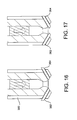
- Figs. 16 and 17 show another embodiment where the casing 360 houses the extendable members 362 and 364. As shown in Fig. 16 , the members 362 and 364 are in a retracted orientation. These members can be activated by an electromechanical device for quick actuation. Fig. 17 shows the members 362 and 364 in a retracted orientation to alter the cone diameter.
- Figs. 18 and 19 shows another embodiment where a slider plate mechanism utilizing slider plates 370 and 372 are utilized.
- Fig. 18 shows the members 370 and 372 in a closed orientation an actuator can reposition the slider plates to an open orientation as shown in Fig. 19 .
- the members 370 and 372 can be operated in one form by way of an electromagnetic device where the outer surface area 374 can for example be a portion of an electromagnetic actuator. Of course other forms of restricting the orifice can be utilized.
Applications Claiming Priority (1)
| Application Number | Priority Date | Filing Date | Title |
|---|---|---|---|
| US11/690,676 US7739985B2 (en) | 2006-03-23 | 2007-03-23 | Internal combustion water injection engine |
Publications (1)
| Publication Number | Publication Date |
|---|---|
| EP2014903A1 true EP2014903A1 (de) | 2009-01-14 |
Family
ID=40076914
Family Applications (1)
| Application Number | Title | Priority Date | Filing Date |
|---|---|---|---|
| EP08005402A Withdrawn EP2014903A1 (de) | 2007-03-23 | 2008-03-20 | Wassereinspritzverbrennungsmotor |
Country Status (1)
| Country | Link |
|---|---|
| EP (1) | EP2014903A1 (de) |
Cited By (5)
| Publication number | Priority date | Publication date | Assignee | Title |
|---|---|---|---|---|
| ITGE20100034A1 (it) * | 2010-04-13 | 2011-10-14 | Novatech Di Elisa Prandi | Full rain : metodo per il controllo termo-barico di motore a combustione interna mediante iniezione di diluente termico. |
| DE102012207907A1 (de) * | 2012-05-11 | 2013-11-14 | Bayerische Motoren Werke Aktiengesellschaft | Wassereinspritzsystem für einen Verbrennungsmotor mit Hochdruckeinspritzleiste und Zusatzvolumen zum Schutz vor Schäden durch Gefrieren des Wassers |
| DE102014222467A1 (de) * | 2014-11-04 | 2016-05-04 | Bayerische Motoren Werke Aktiengesellschaft | Brennkraftmaschine |
| CN105683553A (zh) * | 2013-11-08 | 2016-06-15 | 丰田自动车株式会社 | 缸内喷射式内燃机的水供给控制装置 |
| WO2018050394A1 (de) * | 2016-09-16 | 2018-03-22 | Robert Bosch Gmbh | Wassereinspritzvorrichtung für eine brennkraftmaschine eines kraftfahrzeugs |
Citations (10)
| Publication number | Priority date | Publication date | Assignee | Title |
|---|---|---|---|---|
| WO1986000630A1 (en) | 1984-07-06 | 1986-01-30 | The Dow Chemical Company | Compositions of polyepoxide/polyamine adducts and blocked isocyanates |
| US5012772A (en) * | 1988-06-17 | 1991-05-07 | Sankoshoki Corporation | Internal combustion engine |
| US5154142A (en) * | 1992-03-23 | 1992-10-13 | Adiabatics, Inc. | Ionic combustion system with ignitor assist |
| DE4201836A1 (de) * | 1992-01-24 | 1993-07-29 | Karl Dipl Ing Hein | Verbrennungskraftmaschinen mit kraftstoffaufbereitungseinrichtungen fuer die in ihnen verbrannten kraftstoffe |
| EP0553364A1 (de) * | 1992-01-22 | 1993-08-04 | Mitsubishi Jukogyo Kabushiki Kaisha | Dieselmotor mit Wassereinspritzung |
| US5816228A (en) * | 1997-02-19 | 1998-10-06 | Avl Powertrain Engineering, Inc. | Fuel injection system for clean low viscosity fuels |
| WO1999031204A1 (en) * | 1997-12-18 | 1999-06-24 | Quantum Energy Technologies | Supercritical water fuel composition and combustion system |
| US5937799A (en) * | 1994-09-12 | 1999-08-17 | Binion; W. Sidney | Cylinder water injection engine |
| US6202613B1 (en) | 1998-09-01 | 2001-03-20 | Kioritz Corporation | Four-stroke cycle internal combustion engine |
| EP1319816A2 (de) * | 2001-12-14 | 2003-06-18 | Gerhard Auer | HGIS-Direkteinsprühsystem |
-
2008
- 2008-03-20 EP EP08005402A patent/EP2014903A1/de not_active Withdrawn
Patent Citations (10)
| Publication number | Priority date | Publication date | Assignee | Title |
|---|---|---|---|---|
| WO1986000630A1 (en) | 1984-07-06 | 1986-01-30 | The Dow Chemical Company | Compositions of polyepoxide/polyamine adducts and blocked isocyanates |
| US5012772A (en) * | 1988-06-17 | 1991-05-07 | Sankoshoki Corporation | Internal combustion engine |
| EP0553364A1 (de) * | 1992-01-22 | 1993-08-04 | Mitsubishi Jukogyo Kabushiki Kaisha | Dieselmotor mit Wassereinspritzung |
| DE4201836A1 (de) * | 1992-01-24 | 1993-07-29 | Karl Dipl Ing Hein | Verbrennungskraftmaschinen mit kraftstoffaufbereitungseinrichtungen fuer die in ihnen verbrannten kraftstoffe |
| US5154142A (en) * | 1992-03-23 | 1992-10-13 | Adiabatics, Inc. | Ionic combustion system with ignitor assist |
| US5937799A (en) * | 1994-09-12 | 1999-08-17 | Binion; W. Sidney | Cylinder water injection engine |
| US5816228A (en) * | 1997-02-19 | 1998-10-06 | Avl Powertrain Engineering, Inc. | Fuel injection system for clean low viscosity fuels |
| WO1999031204A1 (en) * | 1997-12-18 | 1999-06-24 | Quantum Energy Technologies | Supercritical water fuel composition and combustion system |
| US6202613B1 (en) | 1998-09-01 | 2001-03-20 | Kioritz Corporation | Four-stroke cycle internal combustion engine |
| EP1319816A2 (de) * | 2001-12-14 | 2003-06-18 | Gerhard Auer | HGIS-Direkteinsprühsystem |
Cited By (7)
| Publication number | Priority date | Publication date | Assignee | Title |
|---|---|---|---|---|
| ITGE20100034A1 (it) * | 2010-04-13 | 2011-10-14 | Novatech Di Elisa Prandi | Full rain : metodo per il controllo termo-barico di motore a combustione interna mediante iniezione di diluente termico. |
| DE102012207907A1 (de) * | 2012-05-11 | 2013-11-14 | Bayerische Motoren Werke Aktiengesellschaft | Wassereinspritzsystem für einen Verbrennungsmotor mit Hochdruckeinspritzleiste und Zusatzvolumen zum Schutz vor Schäden durch Gefrieren des Wassers |
| CN105683553A (zh) * | 2013-11-08 | 2016-06-15 | 丰田自动车株式会社 | 缸内喷射式内燃机的水供给控制装置 |
| CN105683553B (zh) * | 2013-11-08 | 2019-05-03 | 丰田自动车株式会社 | 缸内喷射式内燃机的水供给控制装置 |
| DE102014222467A1 (de) * | 2014-11-04 | 2016-05-04 | Bayerische Motoren Werke Aktiengesellschaft | Brennkraftmaschine |
| WO2018050394A1 (de) * | 2016-09-16 | 2018-03-22 | Robert Bosch Gmbh | Wassereinspritzvorrichtung für eine brennkraftmaschine eines kraftfahrzeugs |
| CN109715930A (zh) * | 2016-09-16 | 2019-05-03 | 罗伯特·博世有限公司 | 用于机动车的内燃机的喷水设备 |
Similar Documents
| Publication | Publication Date | Title |
|---|---|---|
| US7798119B2 (en) | Internal combustion water injection engine | |
| US5353992A (en) | Multi-hole injector nozzle tip with low hydraulic plume penetration and large cloud-forming properties | |
| EP0639710B1 (de) | Brennkraftmaschine mit Selbstzündung und Verbrennungsverfahren | |
| US6981484B2 (en) | Internal combustion engine with divided combustion chamber | |
| JP4007310B2 (ja) | 2種類の燃料を用いる予混合圧縮自着火運転可能な内燃機関 | |
| EP2014903A1 (de) | Wassereinspritzverbrennungsmotor | |
| CN1126864C (zh) | 内燃机 | |
| US5249557A (en) | Fuel injection system for two cycle engine | |
| CN102918240B (zh) | 在内燃机中用于供给燃料的方法和装置 | |
| CN106640460B (zh) | 具有相切翅片的环形喷嘴喷射器 | |
| WO2012155599A1 (zh) | 高效内燃发动机 | |
| CN103180600A (zh) | 内燃机构用燃料喷射阀 | |
| JP6670718B2 (ja) | 制御装置 | |
| CN100441849C (zh) | 内燃机的燃料供应装置 | |
| CN107407223B (zh) | 直喷发动机的燃料喷射控制装置 | |
| CN103382913A (zh) | 一种复合式旋转喷油嘴 | |
| JP4357800B2 (ja) | 内燃機関の燃料供給装置 | |
| CN107448317B (zh) | 控制内燃发动机的燃料喷雾持续时间的方法 | |
| JP3617252B2 (ja) | 圧縮着火式エンジン | |
| CN104612836A (zh) | 内燃机及运行内燃机的方法 | |
| US10927804B2 (en) | Direct fuel injector | |
| CN1316153C (zh) | 气缸内喷射燃油式内燃机 | |
| JP5837849B2 (ja) | 筒内噴射式エンジンの制御装置 | |
| UA87733C2 (ru) | Способ смесеобразования в камере сгорания двигателя внутреннего сгорания и двигатель внутреннего сгорания с расслоением топливовоздушного заряда и с принудительным зажиганием при непосредственном впрыскивании топлива | |
| JP2008115794A (ja) | 内燃機関の点火装置 |
Legal Events
| Date | Code | Title | Description |
|---|---|---|---|
| PUAI | Public reference made under article 153(3) epc to a published international application that has entered the european phase |
Free format text: ORIGINAL CODE: 0009012 |
|
| AK | Designated contracting states |
Kind code of ref document: A1 Designated state(s): AT BE BG CH CY CZ DE DK EE ES FI FR GB GR HR HU IE IS IT LI LT LU LV MC MT NL NO PL PT RO SE SI SK TR |
|
| AX | Request for extension of the european patent |
Extension state: AL BA MK RS |
|
| 17P | Request for examination filed |
Effective date: 20090714 |
|
| AKX | Designation fees paid |
Designated state(s): AT BE BG CH CY CZ DE DK EE ES FI FR GB GR HR HU IE IS IT LI LT LU LV MC MT NL NO PL PT RO SE SI SK TR |
|
| 17Q | First examination report despatched |
Effective date: 20090826 |
|
| STAA | Information on the status of an ep patent application or granted ep patent |
Free format text: STATUS: THE APPLICATION IS DEEMED TO BE WITHDRAWN |
|
| 18D | Application deemed to be withdrawn |
Effective date: 20121002 |