EP1319795B1 - Appareil d'entraînement de tubes avec système de commande dans une protection solaire ou un dispositif d'occultation - Google Patents
Appareil d'entraînement de tubes avec système de commande dans une protection solaire ou un dispositif d'occultation Download PDFInfo
- Publication number
- EP1319795B1 EP1319795B1 EP02028289.3A EP02028289A EP1319795B1 EP 1319795 B1 EP1319795 B1 EP 1319795B1 EP 02028289 A EP02028289 A EP 02028289A EP 1319795 B1 EP1319795 B1 EP 1319795B1
- Authority
- EP
- European Patent Office
- Prior art keywords
- shading
- tubular drive
- drive according
- motor
- darkening
- Prior art date
- Legal status (The legal status is an assumption and is not a legal conclusion. Google has not performed a legal analysis and makes no representation as to the accuracy of the status listed.)
- Expired - Lifetime
Links
Images
Classifications
-
- E—FIXED CONSTRUCTIONS
- E06—DOORS, WINDOWS, SHUTTERS, OR ROLLER BLINDS IN GENERAL; LADDERS
- E06B—FIXED OR MOVABLE CLOSURES FOR OPENINGS IN BUILDINGS, VEHICLES, FENCES OR LIKE ENCLOSURES IN GENERAL, e.g. DOORS, WINDOWS, BLINDS, GATES
- E06B9/00—Screening or protective devices for wall or similar openings, with or without operating or securing mechanisms; Closures of similar construction
- E06B9/56—Operating, guiding or securing devices or arrangements for roll-type closures; Spring drums; Tape drums; Counterweighting arrangements therefor
- E06B9/68—Operating devices or mechanisms, e.g. with electric drive
-
- E—FIXED CONSTRUCTIONS
- E06—DOORS, WINDOWS, SHUTTERS, OR ROLLER BLINDS IN GENERAL; LADDERS
- E06B—FIXED OR MOVABLE CLOSURES FOR OPENINGS IN BUILDINGS, VEHICLES, FENCES OR LIKE ENCLOSURES IN GENERAL, e.g. DOORS, WINDOWS, BLINDS, GATES
- E06B9/00—Screening or protective devices for wall or similar openings, with or without operating or securing mechanisms; Closures of similar construction
- E06B9/56—Operating, guiding or securing devices or arrangements for roll-type closures; Spring drums; Tape drums; Counterweighting arrangements therefor
- E06B9/80—Safety measures against dropping or unauthorised opening; Braking or immobilising devices; Devices for limiting unrolling
- E06B9/82—Safety measures against dropping or unauthorised opening; Braking or immobilising devices; Devices for limiting unrolling automatic
- E06B9/86—Safety measures against dropping or unauthorised opening; Braking or immobilising devices; Devices for limiting unrolling automatic against unauthorised opening
Definitions
- the invention relates to a controlled tubular drive a shading or darkening element, such as Clarbahbehanges of textile material, or a roller shutter, wherein the shading or darkening element is rollable on a winding shaft and a closure rail and optionally a locking mechanism for the unrolled position, wherein the Control is provided with a commander for starting the rolling or rolling movement.
- a shading or darkening element such as Clarbahbehanges of textile material, or a roller shutter
- a controlled tubular drive according to the preamble of claim 1 is known from EP-A 0 315 036 known.
- a locking mechanism for the terminus rail is provided there.
- pivotable elements or hooks on the end rail interact with stationary locking elements in the guide rails.
- the locking then takes place so that the hooks of the closure rail when rolling the cloth over the stationary locking elements in the guide rails pass away and then in a short reversing movement of the cloth in the Engage locking elements, which stops the end rail and the cloth is stretched and tightened by the further movement of the engine.
- This clamping can only be done by a counter-movement.
- the closing rail is moved to a lower position.
- the drive is reversed, causing the drive to run in reverse, the locking elements engage and the fabric is tensioned.
- the winding shaft For retracting the awning, the winding shaft is first set in the sense of lowering the drop bar in motion, thereby unlocking the detent gear takes place. Thereafter, the winding shaft is rotated in the sense of winding the awning fabric, whereby the lock is disengaged from the locking gear and the awning can be retracted freely.
- the individual movements of the cloth are realized in the prior art via external controls with predetermined time constants.
- a disadvantage of this prior art is that the drive and the control must always be set to the particular circumstances. Often there is no sufficient process reliability. Also, the attitude for the fitter - especially if it is not trained personnel - proves to be quite difficult and time consuming. Another disadvantage is the stress on the cloth, which is loaded with the rated torque of the drive. Through this strong stretching, the cloth loses its elasticity and can be overstretched.
- the object of the invention is therefore to propose a controlled tubular drive for a shading or darkening element of the type mentioned, which is easily adjustable on the one hand for unskilled fitters and on the other hand, not overstretched even in years of operation, the shading or obscuring.
- the invention thus has two special features over the controls according to the prior art.
- the control moves regardless of whether an up or a move is desired, the shading or darkening element always in two directions when the unrolled end or the intended locking position is reached.
- the succession of rotational movements depends not only on the switch position or position of the commander, but also where the shading or darkening element (more precisely its end rail) is currently located (position control) and what resistance its further movement requires there (moment control).
- a position control and a torque control is used according to the invention, whereby the on-site initial setting is much easier - it can namely usually already specified by the factory.
- overstretching of the shading element is avoided by incorrect settings.
- the drive does not pull with the rated torque of the motor on the shading element, but only expands it by a certain, factory-set distance or up to a factory preset maximum torque, which or material is not overloaded, but is still sufficiently taut to flutter and rattling movements to avoid by the wind.
- Position control means that the control measures the position of the shading or darkening element of the blind or the end rail and uses this as a manipulated variable (as a trigger for switching on or off).
- Torque control means that the torque of the drive is measured and used as a manipulated variable. The torque control is particularly material-friendly, since a once preset voltage value is never exceeded.
- a combination of both controls is provided. This allows the shading or darkening element to reach a certain position be moved and then (after snapping) to a certain position or to a certain force (moment) to be withdrawn.
- incremental encoders are provided on the winding shaft for position determination. This allows a particularly favorable and accurate position determination. Any occurring elongations are compensated automatically, for example by means of a difference determination between an upper defined position and a lower defined position of the shading or darkening element.
- all devices or sensors suitable for this purpose can be used to measure the moment of the shading or darkening element or the end rail.
- the measurement of the torque to be applied can be done via force gauges or springs.
- the drive is an electric tubular motor used, which is housed together with gear in the winding shaft. This is a common technique that has been proven in many awnings or roller shutters.
- the invention is also applicable to blinds.
- the winding shaft above the building opening, so the window or door arranged so that when rolling the shading or darkening this building opening closed by gravity, for example, the screen so is approached, and ascended when rolling up the screen. It is also possible to reverse this arrangement, so that the winding shaft is below the window and the shading element is raised upwards, thereby closing the building opening. In this case, of course, gravity can not be the driving force, but a motor must pull the closing rail with the curtain from the wound position by means of a pull rope. It is also possible that the winding shaft is attached to the left or right of the opening and the curtain is pulled by a lateral movement.
- the left and right of the building opening guide rails for the end rail and / or for the Beschattungsrymoi obscuring element are provided. Guiding the end rail is recommended for longer running distances, especially for large windows or doors, so that a certainty and definition of the travel is given.
- a guide of the fabric in the side rail also seals laterally from the sun's rays and, with appropriate fabrics, even allows for an absolute eclipse of the room behind the window.
- a locking mechanism known per se which locks or releases when the direction of rotation.
- Such locking mechanisms are known from ballpoint pens or cabinet doors with vertical axis, as they are particularly used in kitchens, in various designs. Sliding in one direction is always possible (opening), while sliding over in the other direction (closing) is once locked (latching to hold open) and next time is released (closing).
- a latching mechanism which has a spring-loaded, pivotable cam on each side of the end rail.
- This cam cooperates with a nose on the building side as a detent element, which always allows the cam to slide over in one direction (downwards), whereas a movement in the other direction (upward) either leads to a locking or allows it to slide over depending on the position of the cam.
- the locking position and the end positions are normally provided in the vicinity of the unrolled end position. This means that the shading or darkening element is completely undisturbed or unwound over long distances of its travel, while a locking takes place in the end position.
- stop options are provided at intermediate positions, so that the curtain can also be locked there.
- a lock may be provided, so that the shading or darkening element partially shaded, but still sufficient light passes.
- the sensors for the position forward their information to an evaluation circuit, which in turn operates current reversing means, such as changeover relay, which supply the motor with the current in the desired polarity for ascending or descending.
- current reversing means such as changeover relay
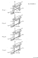
- FIGS. 1 to 4 each show a Sonnenschutzbehang or Screen 2, which is rolled up on a above the building opening (window or door) winding shaft 4 and has at its lower end a cover rail 6.
- a motor 8 is provided in the winding shaft 4.
- the components transmission and control are not drawn here.
- the end rail 6 is guided in two guide rails 10, which are attached to the left and right of the building opening.
- the reference numerals P1, P2, P3 and P4 show four positions of the end rail 6, P1 corresponding to the wound-up position and the positions P2, P3 and P4 being in the vicinity of the shut-down end position.
- FIG. 1 Screen 2 is shown in a middle position.
- the building opening is approximately half hidden, and the curtain 2 is closed by a rotational movement of the motor 8 down. This rotational movement for closing was triggered by pressing a switch, not shown.
- FIG. 2 shows the curtain 2 a little later, namely after a further access, after the end rail 6 has passed the position P2 and has reached the position P3.
- the motor 8 is stopped according to the invention by the controller.
- the hanging 2 then remains (position-controlled) stand.
- This position (position P3) is so far down that the locking cams of the locking mechanism of the end rail 6 are already below the building-fixed lugs that prevent "snapping" of the curtain.
- Fig. 3 shows the further course of the Zufahrhik.
- the circuit polts the current to the motor 8 after stopping in position P3, as a result of which the curtain 2 is rearranged again in part. Now - in this countermovement - grab the noses in the stationary locking elements and the fabric of the curtain 2 is stretched by the short further movement of the motor 8 in the direction of approach.
- the end rail In the position in FIG. 4 is shown, the end rail is in the position P2, the lock is locked and prevents the end rail 6 further booting.
- the controller stops the motor either position-controlled or when reaching a certain maximum torque.
- the fabric is stretched with a predetermined tension and is therefore against rattling and others Wind noise protected. This is also the end position for the shut down curtain 2.
- the sequence of shutdown and the short startup and tensioning is carried out according to the invention automatically and position or torque controlled, without the operator person at the switch 18 must remain responsive or switch. Due to the small distance between P2 and P3, only a short, factory-set travel path in the opposite direction (or a rotation up to a preset torque) is given, so that an excessive loading or stretching of the fabric of the curtain 2 is avoided.
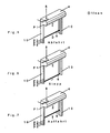
- FIGS. 5 to 7 show three different positions of the curtain 2 when driving (opening) by means of a controller according to the invention.
- Fig. 5 is shown the beginning of the Auffahrzi.
- the controller for the first time commands the motor 8 to drive “downwards", so that the closing rail 6 of the curtain 2 moves from position P2 to position P4, which is still slightly below the position P3 is located.
- the mechanism unlocks.
- the inhibiting cams are folded over so that they do not engage in the noses when driving past at positions P2 or P3, but slide over them.
- Fig. 6 shows the position of the end rail 6 of the curtain 2 in the lowest position P4.
- the controller stops the motor 8 (in this example by a position control) and polts via a relay or otherwise, the current is controlled so that the motor 8 changes its direction of rotation.
- the movements are not timed or even by the user, but automatically controlled.
- FIG. 7 It starts the actual upward movement. This is in FIG. 7 shown.
- the curtain 2 is wound up on its winding shaft 4 and releases the building opening.
- the end rail 6 moves up to the position P1, in which the motor 8 is stopped and the raising of the curtain 2 is completed. Again, a position control ("arrived at the top") or a torque control ("can not continue with reasonable force”) can be used again.
- the initial setting is easier than in the prior art. Since it is not working in reverse operation via torque changes or position detection, but over time constants, the individual time constants must be taught during initial setting (running time from top to bottom, running time from bottom to a few cm above the lock, running time slightly above the lock to the unlocking).
- the mechanic moves to the initial setting to the upper end position.
- the drive automatically detects the upper position P1.
- the fitter drives the drive via the position P3 into the lock.
- the circuit recognizes by means of torque change the lower position P2.
- Positions P3 and P4 are now set automatically by the drive. In the prior art, therefore, the fitters must therefore additionally set the path between position P1 and position P4.
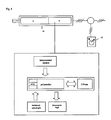
- FIG. 8 shows an embodiment of a controller according to the invention.
- An electromechanical unit for opening and closing a sunshade curtain (screen 2) consists of a motor gear unit 12 and a control unit 14, which are mounted together in a housing 16.
- This housing 16 may preferably be located in the winding shaft for the screen 2.
- the control unit 14 is drawn again enlarged and contains a microprocessor ( ⁇ -controller) with read-only memory (ROM) and a writable, non-volatile memory (E 2 Prom).
- the microprocessor has an input for the data of the incremental transducer, thus knows the position of the screen 2, and receives commands from the command response logic.
- the output of the microprocessor is connected to a current loop logic.
- a single travel command (“up” or “down”) issued at the switch 18 causes the control unit 14 to move the curtain to certain positions (P1 to P4) while changing the directions of rotation, as described above.
- the positions were previously communicated to the control unit 14 in connection with the sole teach-in of the end positions of the curtain and stored in the non-volatile memory (E 2 Prom).
- the control unit 14 causes the motor gear unit 12 to initiate a rotation command cycle. which consists of at least two rotations undefined duration with different direction of rotation. Its start and end conditions are position-dependent and torque-dependent.
Landscapes
- Engineering & Computer Science (AREA)
- Structural Engineering (AREA)
- Architecture (AREA)
- Civil Engineering (AREA)
- Operating, Guiding And Securing Of Roll- Type Closing Members (AREA)
Claims (7)
- Entraînement tubulaire asservi pour élément d'ombrage ou d'assombrissement, par exemple un rideau de protection solaire en matériau textile, en particulier un écran (2) ou un volet, l'élément d'ombrage ou d'assombrissement pouvant être enroulé sur un arbre d'enroulement (4) et présentant un rail de fermeture (6) ainsi qu'un mécanisme de verrouillage de la position déroulée, la commande étant dotée d'un donneur d'ordres (18) qui lance le déplacement d'enroulement ou de déroulement,
caractérisé en ce que
la commande présente une unité de commande (14) qui, partant de grandeurs de réglage de la position de l'élément et du couple de rotation de l'entraînement tubulaire, exécute pour un seul actionnement du donneur d'ordres au moins deux déplacements de l'élément d'ombrage dans des directions différentes, un compteur incrémentiel étant prévu pour déterminer la position. - Entraînement tubulaire selon la revendication 1, caractérisé en ce qu'il présente un moteur électrique (8) et en particulier un moteur tubulaire disposé dans l'arbre d'enroulement (4).
- Entraînement tubulaire selon l'une des revendications précédentes, caractérisé en ce que l'arbre d'enroulement (4) est disposé au-dessus de l'ouverture du bâtiment et en ce que l'élément (2) d'ombrage ou d'assombrissement est déplacé par la force de gravité lors du déroulement devant l'ouverture du bâtiment et par la force du moteur lors de l'enroulement.
- Entraînement tubulaire selon l'une des revendications précédentes, caractérisé en ce que des rails de guidage (10) du rail de fermeture (6) et/ou de l'élément (2) d'ombrage ou d'assombrissement sont prévus à gauche et à droite de l'ouverture du bâtiment.
- Entraînement tubulaire selon l'une des revendications précédentes, caractérisé en ce que le mécanisme de verrouillage est verrouillé ou se libère en cas de changement du sens de rotation.
- Entraînement tubulaire selon l'une des revendications précédentes, caractérisé en ce qu'un circuit d'évaluation et un relais d'inversion sont prévus pour la commande du moteur (8).
- Entraînement tubulaire selon l'une des revendications précédentes, caractérisé en ce que l'unité de commande (14) présente une mémoire non volatile (E 2 Prom) qui conserve des positions (P1-P4) du rail de fermeture de l'élément (2) d'ombrage ou d'assombrissement et une logique d'exécution d'un cycle d'ordres de rotation qui exécute au moins deux déplacements de rotation différents pour un seul ordre de commande.
Applications Claiming Priority (2)
| Application Number | Priority Date | Filing Date | Title |
|---|---|---|---|
| DE10162034 | 2001-12-17 | ||
| DE10162034 | 2001-12-17 |
Publications (3)
| Publication Number | Publication Date |
|---|---|
| EP1319795A2 EP1319795A2 (fr) | 2003-06-18 |
| EP1319795A3 EP1319795A3 (fr) | 2004-02-04 |
| EP1319795B1 true EP1319795B1 (fr) | 2014-04-02 |
Family
ID=7709578
Family Applications (1)
| Application Number | Title | Priority Date | Filing Date |
|---|---|---|---|
| EP02028289.3A Expired - Lifetime EP1319795B1 (fr) | 2001-12-17 | 2002-12-17 | Appareil d'entraînement de tubes avec système de commande dans une protection solaire ou un dispositif d'occultation |
Country Status (1)
| Country | Link |
|---|---|
| EP (1) | EP1319795B1 (fr) |
Families Citing this family (5)
| Publication number | Priority date | Publication date | Assignee | Title |
|---|---|---|---|---|
| FR2877109B1 (fr) * | 2004-10-25 | 2007-01-19 | Somfy Sas | Procede de perfectionnement d'un ecran motorise et ecran motorise pour sa mise en oeuvre |
| DE102007006396A1 (de) † | 2007-02-05 | 2008-08-07 | Provita Gmbh | Vorrichtung zur Stillstandssteuerung einer motorischen Antriebseinrichtung |
| FR3072411B1 (fr) * | 2017-10-16 | 2019-10-11 | Somfy Activites Sa | Procede de reglage d'une installation de volet roulant munie d'un verrou |
| FR3078358A1 (fr) * | 2018-02-26 | 2019-08-30 | Somfy Activites Sa | Procede de commande automatisee d'une installation de volet roulant |
| EP3470617B1 (fr) * | 2017-10-16 | 2020-09-23 | Somfy Activites Sa | Procede de commande automatisee d'une installation de volet roulant et installation d'ecran motorise |
Citations (1)
| Publication number | Priority date | Publication date | Assignee | Title |
|---|---|---|---|---|
| EP0845572A1 (fr) * | 1996-11-27 | 1998-06-03 | Finvetro S.r.l. | Dispositif pour contrôler et pour mouvoir un moyen d'obturation de la lumière dans une unité de double vitrage |
Family Cites Families (6)
| Publication number | Priority date | Publication date | Assignee | Title |
|---|---|---|---|---|
| DE3737707A1 (de) * | 1987-11-06 | 1989-05-24 | Clauss Markisen | Verriegelbare senkrechtmarkise |
| DE4442948A1 (de) * | 1993-12-04 | 1995-06-08 | Braselmann Klaus Andre | Vorrichtung zur Steuerung von beweglichen Einrichtungen wie Rolltoren o. dgl. |
| DE19519020A1 (de) * | 1995-05-24 | 1996-11-28 | Bosch Gmbh Robert | Vorrichtung zur elektronischen Steuerung der Bewegungen eines Rolladens |
| DE19615554A1 (de) * | 1996-04-19 | 1997-10-23 | Abb Patent Gmbh | Verfahren und Einrichtung zur Steuerung einer Verdunkelungsanlage |
| NL1007445C2 (nl) * | 1997-11-04 | 1999-05-06 | Windvast N V | Zonwering met blokkeringsinrichting. |
| JP3792088B2 (ja) | 1999-12-15 | 2006-06-28 | 文化シヤッター株式会社 | 閉鎖装置 |
-
2002
- 2002-12-17 EP EP02028289.3A patent/EP1319795B1/fr not_active Expired - Lifetime
Patent Citations (1)
| Publication number | Priority date | Publication date | Assignee | Title |
|---|---|---|---|---|
| EP0845572A1 (fr) * | 1996-11-27 | 1998-06-03 | Finvetro S.r.l. | Dispositif pour contrôler et pour mouvoir un moyen d'obturation de la lumière dans une unité de double vitrage |
Also Published As
| Publication number | Publication date |
|---|---|
| EP1319795A3 (fr) | 2004-02-04 |
| EP1319795A2 (fr) | 2003-06-18 |
Similar Documents
| Publication | Publication Date | Title |
|---|---|---|
| DE602005001488T2 (de) | Motorgetriebener Schirm und Verfahren zu seiner Betätigung | |
| EP0770757B2 (fr) | Méthode pour actionner des vélums ou des choses pareilles par moteur électrique | |
| EP1970235A2 (fr) | Store de fenêtre latérale doté d'un entraînement à corde | |
| EP1367192B1 (fr) | Store, en particulier store pour jardins d'hiver | |
| EP2060421A1 (fr) | Agencement de store doté d'un entraînement à friction réduite | |
| DE4230729A1 (de) | Vorrichtung zur antriebsabschaltung des motors elektrisch betriebener rollaeden, rolltore, markisen o. dgl. | |
| DE2529729A1 (de) | Vorrichtung zum ueberdecken einer automatisch arbeitenden arbeitsmaschine | |
| EP1739275A2 (fr) | Volet roulant avec dispositif anti-pincement éléctronique | |
| EP1319795B1 (fr) | Appareil d'entraînement de tubes avec système de commande dans une protection solaire ou un dispositif d'occultation | |
| DE4034614C2 (fr) | ||
| EP2450523A2 (fr) | Entraînement pour un dispositif d'assombrissement | |
| EP0534894B1 (fr) | Dispositif pour une déconnexion d'entraînement d'un moteur de volets roulants, de portes à rideaux, de stores et de choses similaires | |
| EP2103773A2 (fr) | Dispositif de protection, notamment moustiquaire | |
| DE69906314T2 (de) | Fenster-abschirmvorrichtung und eine universelle befestigungs- und parallelführungsvorrichtung für eine fenster-abschirmvorrichtung | |
| DE19861119B4 (de) | Rollladensteuerung | |
| WO2018134326A1 (fr) | Store pare-soleil muni d'un volet en partie fermé lorsque le rideau est déployé | |
| DE3225099A1 (de) | Verschlusseinrichtung | |
| DE10319893B4 (de) | Steuereinrichtung für Sonnenschutzrollos und verstellbare Fensterscheiben von Kraftfahrzeugen | |
| EP1083291B1 (fr) | Dispositif d'entraínement éléctrique pour volet roulant | |
| EP2138673B2 (fr) | Installation de protection solaire dotée d'un dispositif de retournement d'urgence | |
| EP1359284B1 (fr) | Dispositif de commande d'un volet roulant | |
| EP2186989A2 (fr) | Commande de moteur | |
| DE102011113151A1 (de) | Rauch- oder Brandschutzabdeckung zum Verschließen einer Gebäudeöffnung | |
| EP3088652B1 (fr) | Procédé de mise en marche de fermeture de bâtiment automatique, dispositif d'entraînement de fermeture de bâtiment destiné a être utilisé dans le procédé et fermeture de bâtiment automatique | |
| EP3798405B1 (fr) | Écran d'obscurcissement pour un store à lamelles |
Legal Events
| Date | Code | Title | Description |
|---|---|---|---|
| PUAI | Public reference made under article 153(3) epc to a published international application that has entered the european phase |
Free format text: ORIGINAL CODE: 0009012 |
|
| AK | Designated contracting states |
Designated state(s): AT BE BG CH CY CZ DE DK EE ES FI FR GB GR IE IT LI LU MC NL PT SE SI SK TR |
|
| AX | Request for extension of the european patent |
Extension state: AL LT LV MK RO |
|
| PUAL | Search report despatched |
Free format text: ORIGINAL CODE: 0009013 |
|
| AK | Designated contracting states |
Kind code of ref document: A3 Designated state(s): AT BE BG CH CY CZ DE DK EE ES FI FR GB GR IE IT LI LU MC NL PT SE SI SK TR |
|
| AX | Request for extension of the european patent |
Extension state: AL LT LV MK RO |
|
| 17P | Request for examination filed |
Effective date: 20040713 |
|
| AKX | Designation fees paid |
Designated state(s): AT BE BG CH CY CZ DE DK EE ES FI FR GB GR IE IT LI LU MC NL PT SE SI SK TR |
|
| 17Q | First examination report despatched |
Effective date: 20040927 |
|
| GRAP | Despatch of communication of intention to grant a patent |
Free format text: ORIGINAL CODE: EPIDOSNIGR1 |
|
| GRAS | Grant fee paid |
Free format text: ORIGINAL CODE: EPIDOSNIGR3 |
|
| 17Q | First examination report despatched |
Effective date: 20040927 |
|
| GRAJ | Information related to disapproval of communication of intention to grant by the applicant or resumption of examination proceedings by the epo deleted |
Free format text: ORIGINAL CODE: EPIDOSDIGR1 |
|
| GRAL | Information related to payment of fee for publishing/printing deleted |
Free format text: ORIGINAL CODE: EPIDOSDIGR3 |
|
| INTC | Intention to grant announced (deleted) | ||
| GRAP | Despatch of communication of intention to grant a patent |
Free format text: ORIGINAL CODE: EPIDOSNIGR1 |
|
| INTG | Intention to grant announced |
Effective date: 20130805 |
|
| GRAS | Grant fee paid |
Free format text: ORIGINAL CODE: EPIDOSNIGR3 |
|
| GRAA | (expected) grant |
Free format text: ORIGINAL CODE: 0009210 |
|
| STAA | Information on the status of an ep patent application or granted ep patent |
Free format text: STATUS: THE PATENT HAS BEEN GRANTED |
|
| AK | Designated contracting states |
Kind code of ref document: B1 Designated state(s): AT BE BG CH CY CZ DE DK EE ES FI FR GB GR IE IT LI LU MC NL PT SE SI SK TR |
|
| REG | Reference to a national code |
Ref country code: GB Ref legal event code: FG4D Free format text: NOT ENGLISH |
|
| REG | Reference to a national code |
Ref country code: CH Ref legal event code: EP Ref country code: AT Ref legal event code: REF Ref document number: 660271 Country of ref document: AT Kind code of ref document: T Effective date: 20140415 |
|
| REG | Reference to a national code |
Ref country code: IE Ref legal event code: FG4D Free format text: LANGUAGE OF EP DOCUMENT: GERMAN |
|
| REG | Reference to a national code |
Ref country code: DE Ref legal event code: R096 Ref document number: 50215902 Country of ref document: DE Effective date: 20140515 |
|
| REG | Reference to a national code |
Ref country code: SE Ref legal event code: TRGR |
|
| REG | Reference to a national code |
Ref country code: NL Ref legal event code: T3 |
|
| PG25 | Lapsed in a contracting state [announced via postgrant information from national office to epo] |
Ref country code: GR Free format text: LAPSE BECAUSE OF FAILURE TO SUBMIT A TRANSLATION OF THE DESCRIPTION OR TO PAY THE FEE WITHIN THE PRESCRIBED TIME-LIMIT Effective date: 20140703 Ref country code: CY Free format text: LAPSE BECAUSE OF FAILURE TO SUBMIT A TRANSLATION OF THE DESCRIPTION OR TO PAY THE FEE WITHIN THE PRESCRIBED TIME-LIMIT Effective date: 20140402 Ref country code: BG Free format text: LAPSE BECAUSE OF FAILURE TO SUBMIT A TRANSLATION OF THE DESCRIPTION OR TO PAY THE FEE WITHIN THE PRESCRIBED TIME-LIMIT Effective date: 20140702 Ref country code: FI Free format text: LAPSE BECAUSE OF FAILURE TO SUBMIT A TRANSLATION OF THE DESCRIPTION OR TO PAY THE FEE WITHIN THE PRESCRIBED TIME-LIMIT Effective date: 20140402 Ref country code: CZ Free format text: LAPSE BECAUSE OF FAILURE TO SUBMIT A TRANSLATION OF THE DESCRIPTION OR TO PAY THE FEE WITHIN THE PRESCRIBED TIME-LIMIT Effective date: 20140402 |
|
| PG25 | Lapsed in a contracting state [announced via postgrant information from national office to epo] |
Ref country code: ES Free format text: LAPSE BECAUSE OF FAILURE TO SUBMIT A TRANSLATION OF THE DESCRIPTION OR TO PAY THE FEE WITHIN THE PRESCRIBED TIME-LIMIT Effective date: 20140402 |
|
| PG25 | Lapsed in a contracting state [announced via postgrant information from national office to epo] |
Ref country code: PT Free format text: LAPSE BECAUSE OF FAILURE TO SUBMIT A TRANSLATION OF THE DESCRIPTION OR TO PAY THE FEE WITHIN THE PRESCRIBED TIME-LIMIT Effective date: 20140804 |
|
| REG | Reference to a national code |
Ref country code: DE Ref legal event code: R097 Ref document number: 50215902 Country of ref document: DE |
|
| PG25 | Lapsed in a contracting state [announced via postgrant information from national office to epo] |
Ref country code: SK Free format text: LAPSE BECAUSE OF FAILURE TO SUBMIT A TRANSLATION OF THE DESCRIPTION OR TO PAY THE FEE WITHIN THE PRESCRIBED TIME-LIMIT Effective date: 20140402 Ref country code: EE Free format text: LAPSE BECAUSE OF FAILURE TO SUBMIT A TRANSLATION OF THE DESCRIPTION OR TO PAY THE FEE WITHIN THE PRESCRIBED TIME-LIMIT Effective date: 20140402 Ref country code: DK Free format text: LAPSE BECAUSE OF FAILURE TO SUBMIT A TRANSLATION OF THE DESCRIPTION OR TO PAY THE FEE WITHIN THE PRESCRIBED TIME-LIMIT Effective date: 20140402 |
|
| PGFP | Annual fee paid to national office [announced via postgrant information from national office to epo] |
Ref country code: SE Payment date: 20141219 Year of fee payment: 13 Ref country code: CH Payment date: 20141219 Year of fee payment: 13 |
|
| PLBE | No opposition filed within time limit |
Free format text: ORIGINAL CODE: 0009261 |
|
| STAA | Information on the status of an ep patent application or granted ep patent |
Free format text: STATUS: NO OPPOSITION FILED WITHIN TIME LIMIT |
|
| PGFP | Annual fee paid to national office [announced via postgrant information from national office to epo] |
Ref country code: AT Payment date: 20141222 Year of fee payment: 13 Ref country code: NL Payment date: 20141219 Year of fee payment: 13 |
|
| 26N | No opposition filed |
Effective date: 20150106 |
|
| PGFP | Annual fee paid to national office [announced via postgrant information from national office to epo] |
Ref country code: IT Payment date: 20141219 Year of fee payment: 13 |
|
| REG | Reference to a national code |
Ref country code: DE Ref legal event code: R097 Ref document number: 50215902 Country of ref document: DE Effective date: 20150106 |
|
| PGFP | Annual fee paid to national office [announced via postgrant information from national office to epo] |
Ref country code: BE Payment date: 20141219 Year of fee payment: 13 |
|
| PG25 | Lapsed in a contracting state [announced via postgrant information from national office to epo] |
Ref country code: SI Free format text: LAPSE BECAUSE OF FAILURE TO SUBMIT A TRANSLATION OF THE DESCRIPTION OR TO PAY THE FEE WITHIN THE PRESCRIBED TIME-LIMIT Effective date: 20140402 Ref country code: LU Free format text: LAPSE BECAUSE OF FAILURE TO SUBMIT A TRANSLATION OF THE DESCRIPTION OR TO PAY THE FEE WITHIN THE PRESCRIBED TIME-LIMIT Effective date: 20141217 |
|
| GBPC | Gb: european patent ceased through non-payment of renewal fee |
Effective date: 20141217 |
|
| REG | Reference to a national code |
Ref country code: IE Ref legal event code: MM4A |
|
| PG25 | Lapsed in a contracting state [announced via postgrant information from national office to epo] |
Ref country code: GB Free format text: LAPSE BECAUSE OF NON-PAYMENT OF DUE FEES Effective date: 20141217 Ref country code: IE Free format text: LAPSE BECAUSE OF NON-PAYMENT OF DUE FEES Effective date: 20141217 |
|
| REG | Reference to a national code |
Ref country code: FR Ref legal event code: PLFP Year of fee payment: 14 |
|
| PG25 | Lapsed in a contracting state [announced via postgrant information from national office to epo] |
Ref country code: BE Free format text: LAPSE BECAUSE OF NON-PAYMENT OF DUE FEES Effective date: 20151231 Ref country code: MC Free format text: LAPSE BECAUSE OF FAILURE TO SUBMIT A TRANSLATION OF THE DESCRIPTION OR TO PAY THE FEE WITHIN THE PRESCRIBED TIME-LIMIT Effective date: 20140402 |
|
| REG | Reference to a national code |
Ref country code: CH Ref legal event code: PL |
|
| REG | Reference to a national code |
Ref country code: SE Ref legal event code: EUG |
|
| REG | Reference to a national code |
Ref country code: AT Ref legal event code: MM01 Ref document number: 660271 Country of ref document: AT Kind code of ref document: T Effective date: 20151217 |
|
| PG25 | Lapsed in a contracting state [announced via postgrant information from national office to epo] |
Ref country code: SE Free format text: LAPSE BECAUSE OF NON-PAYMENT OF DUE FEES Effective date: 20151218 |
|
| REG | Reference to a national code |
Ref country code: NL Ref legal event code: MM Effective date: 20160101 |
|
| PG25 | Lapsed in a contracting state [announced via postgrant information from national office to epo] |
Ref country code: LI Free format text: LAPSE BECAUSE OF NON-PAYMENT OF DUE FEES Effective date: 20151231 Ref country code: NL Free format text: LAPSE BECAUSE OF NON-PAYMENT OF DUE FEES Effective date: 20160101 Ref country code: CH Free format text: LAPSE BECAUSE OF NON-PAYMENT OF DUE FEES Effective date: 20151231 |
|
| PG25 | Lapsed in a contracting state [announced via postgrant information from national office to epo] |
Ref country code: AT Free format text: LAPSE BECAUSE OF NON-PAYMENT OF DUE FEES Effective date: 20151217 |
|
| REG | Reference to a national code |
Ref country code: FR Ref legal event code: PLFP Year of fee payment: 15 |
|
| PG25 | Lapsed in a contracting state [announced via postgrant information from national office to epo] |
Ref country code: IT Free format text: LAPSE BECAUSE OF NON-PAYMENT OF DUE FEES Effective date: 20151217 |
|
| PG25 | Lapsed in a contracting state [announced via postgrant information from national office to epo] |
Ref country code: TR Free format text: LAPSE BECAUSE OF NON-PAYMENT OF DUE FEES Effective date: 20151217 |
|
| REG | Reference to a national code |
Ref country code: FR Ref legal event code: PLFP Year of fee payment: 16 |
|
| PGFP | Annual fee paid to national office [announced via postgrant information from national office to epo] |
Ref country code: FR Payment date: 20211224 Year of fee payment: 20 Ref country code: DE Payment date: 20211231 Year of fee payment: 20 |
|
| REG | Reference to a national code |
Ref country code: DE Ref legal event code: R071 Ref document number: 50215902 Country of ref document: DE |