EP1319600B1 - Rotary sealing and stripping assembly for a packaging machine - Google Patents
Rotary sealing and stripping assembly for a packaging machine Download PDFInfo
- Publication number
- EP1319600B1 EP1319600B1 EP02258450A EP02258450A EP1319600B1 EP 1319600 B1 EP1319600 B1 EP 1319600B1 EP 02258450 A EP02258450 A EP 02258450A EP 02258450 A EP02258450 A EP 02258450A EP 1319600 B1 EP1319600 B1 EP 1319600B1
- Authority
- EP
- European Patent Office
- Prior art keywords
- bag material
- members
- bar
- machine
- drive
- Prior art date
- Legal status (The legal status is an assumption and is not a legal conclusion. Google has not performed a legal analysis and makes no representation as to the accuracy of the status listed.)
- Expired - Lifetime
Links
- 238000007789 sealing Methods 0.000 title claims abstract description 24
- 238000004806 packaging method and process Methods 0.000 title claims abstract description 20
- 238000011144 upstream manufacturing Methods 0.000 claims description 3
- 230000004048 modification Effects 0.000 description 3
- 238000012986 modification Methods 0.000 description 3
- 235000013305 food Nutrition 0.000 description 2
- 235000011888 snacks Nutrition 0.000 description 2
Images


Classifications
-
- B—PERFORMING OPERATIONS; TRANSPORTING
- B65—CONVEYING; PACKING; STORING; HANDLING THIN OR FILAMENTARY MATERIAL
- B65B—MACHINES, APPARATUS OR DEVICES FOR, OR METHODS OF, PACKAGING ARTICLES OR MATERIALS; UNPACKING
- B65B51/00—Devices for, or methods of, sealing or securing package folds or closures; Devices for gathering or twisting wrappers, or necks of bags
- B65B51/10—Applying or generating heat or pressure or combinations thereof
- B65B51/26—Devices specially adapted for producing transverse or longitudinal seams in webs or tubes
- B65B51/30—Devices, e.g. jaws, for applying pressure and heat, e.g. for subdividing filled tubes
- B65B51/306—Counter-rotating devices
Definitions
- the present invention relates to rotary packaging machines and more particularly but not exclusively to rotary packaging machines used to package snack foods.
- a rotary packaging machine Disclosed in USA Patent 4,663,917 is a rotary packaging machine.
- the machine includes a pair of sealing jaws that are rotatably driven about parallel spaced generally horizontal axes. Associated with the jaws are stripper members which strip the bag material to inhibit product being located between the sealing jaws. Also associated with the sealing jaws are closer bars that engage the tubular bag material to again inhibit product being located between the jaws.
- the sealing jaws engage the tubular bag material they are generally travelling at the same speed as the bag material. However since the jaws are corrugated the bag material upstream of the jaws is accelerated. This in turn causes the bag material to move between the closer bars to the extent that the bag material initially above the closer bars passes through the closer bars to be located immediately below the closer bars just prior to sealing. This can result in product above the closer bars, particularly in the case of snack foods where there are crumbs, being pulled past the closer bars. This in turn can result in the location of product, such as crumbs, in the area between the sealing jaws. This results in an inferior seal and frequently in the bag material being punctured.
- USA patent 6052971 there is described therein a packaging machine provided with "wiper means" in the form of overlapping engagement portions that strip the bag material and cause the bag material to move upwardly relative to the sealing jaws.
- USA patent 4566253 describes a packaging machine that includes a series of interacting rollers that move the bag material upwardly to thereby strip the bag material by causing the bag material to move between a pair of stripping jaws. The interacting rollers reciprocate lineally in a direction generally transverse of the bag material.
- USA patent 6189301 describes a packaging machine having squeezing bars that are caused to oscillate angularly through approximately 45° to engage the bag material to inhibit product passing through the bag material and being engaged by the sealing jaws. The squeezing bars are mounted separately to the sealing jaws and do not rotate therewith.
- Described in European Patent Publication 0666215A1 is a rotary packaging machine that employs stripper bars and closer bars.
- the closer bars engage the tubular bag material above the sealing jaws to inhibit product being located between the sealing jaws.
- the closer bars of the machine of this document merely close the bag material.
- the jaws engage the tubular bag material, frequently the tubular bag material is moved relative to the closing bars, which movement can result in product, such as crumbs moving past the closer bars and becoming engaged between the sealing jaws. Accordingly a faulty seal can result.
- the deflecting and closing members according to claim 1 include:
- the bar members deflect the tubular bag material laterally in one direction and laterally in the opposite direction to said one direction.
- the bar members are configured to also close the bag material; and said machine further includes strippers that engage the bag material downstream of the bar members in said direction to strip the bag material prior to sealing, said strippers being mounted on the drive members so that each drive member has mounted on it one of the bar members and one of the strippers.
- each deflector bracket is pivotally mounted on its respective drive member so that the bar member moves angularly relative to the respective one of the drive members
- said machine further includes a pair of stripper brackets that support the strippers, each stripper bracket being pivotally mounted on a respective one of the drive members so that the strippers move angularly relative to their respective drive members.
- the machine further includes first springs urging the bar members to a predetermined position from which the bar members are angularly moved relative to said drive members upon engagement with the bag material, and second springs urging the strippers to a predetermined position from which are angularly moved relative to the drive members upon engagement with the bag material.
- said machine includes a mounting member fixed to each drive member, with the stripper brackets and deflector brackets being pivotally attached to a respective one of the mounting members.
- one of the bar members is provided with a longitudinally standing projection and the other bar member with a longitudinally extending recess within which the projection is received with the bag material so as to be deflected thereby.
- one of the bar members includes a longitudinally extending recess and the other bar member a longitudinally extending projection to be received in said recess with said bag material so that said bag material is laterally deflected at three locations spaced along the bag material.
- one of the bar members is located upstream along the bag material relative to the other bar member.
- the deflecting and closing members include a pair of closing members which engage the tubular bag material to close the tubular bag material, and a deflecting member that engages the tubular bag material downstream of the closing members, which deflecting member laterally deflects the tubular bag material.
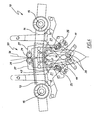
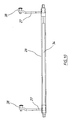
- FIGS 1 and 5 to 1 of the accompanying drawings there is schematically depicted a packaging machine 10.
- the machine 10 is a rotary packaging machine to which there is delivered tubular bag material 36 within which product is located.
- the machine 10 forms transverse seals in the tubular bag material 36 and transversely cuts the tubular bag material 36 to form discrete bags 37.
- the transverse seals are formed and the tubular bag material 36 cut by sealing heads 11 and 12 which are mounted on arms (driver members) 13 and 14. That is the heads 11 and 12 have a knife blade.
- the arms 13 and 14 extend radially from shafts 15 and 16, which shafts 15 and 16 are rotatably driven through repeated revolutions in synchronism in opposite rotational directions about spaced parallel generally horizontal axes.
- the shafts 15 and 16 have generally horizontal, parallel and transversely spaced longitudinal axes. In this embodiment, the axes are substantially stationary except for movement required for the purposes of ensuring correct contact between the sealing heads 11 and 12. However, one or both of the shafts 15 and 16 may be mounted for limited horizontal and/or limited vertical movement if so required.
- each bracket 19 is pivotally supported by means of a shaft 20 on a support (mounting) member 21.
- Each support member 21 in turn being mounted on its associated arm 13, 14 so as to be fixed with respect thereto.
- each bracket 19 and the member 21 Extending between each bracket 19 and the member 21 is a spring 22 urging the associated bracket 19 to engage a stop 23.
- the stops 23 define the rest positions of the stripper bars 17 and 18.
- Each stripper bar 17 and 18 includes an arcuate bag shield 24 and projections 25 between which bag "deflator" springs 26 extend.
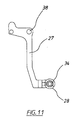
- a pair of support brackets 27 between which there extends tubular bag deflecting members which in this embodiment are in the form of tube closer bars 28 and 29.
- Extending between each bracket 27 and the member 21 is a spring 30 which passes round a pulley 31 to be secured at location 32 on the member 21.
- Each support 21 is urged by the spring 30 to engage a stop 33. Accordingly, the stops 33 define rest positions for the closer bars 28 and 29.
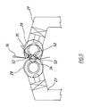
- the closer bar 28 has a longitudinally extending projection 34 that engages within a longitudinally extending recess 35 of the bar 29.
- the tubular bag material 36 When the projection 34 enters the recess 35, together with the tubular bag material 36, the tubular bag material 36 is caused to follow a tortuous path, that is it is first deflected in a direction transverse of the normal direction of travel of the tubular bag material 36, and then is subsequently deflected in the reverse direction. That is the bag material 36 is deflected at three longitudinally spaced locations 52.
- the brackets 27 are each pivotally supported by means of a shaft 38 on the associated support member 21. As the support members 21 are attached to and rotate with the arms 13 and 14, the bars 28 and 29 not only move angularly with the heads 11 and 12, but can also angularly movable relative to the heads 11 and 12 as a result of the brackets 27 being pivotally mounted on the support members 21.
- sealing heads 11 and 12 are essentially fixed relative to their associated arms 13 and 14. There is some limited movement to facilitate sealing.
- the above-described arrangement is also applicable to "flat jaw" rotary machines, that is, arrangements in which the heads 11 and 12 follow arcuate paths but are connected by rods so that their orientation does not change during their cycle.
- tube closer bars 28 and 29 may be employed (not necessarily having the recess 35 and projection 34) which are not aligned, that is, the bar 28 for example could be angularly ahead of the bar 29 so that they are no longer transversely aligned when engaged with the bag material 36.
- the tubular bag material 36 is again deflected in a first direction transverse of the normal direction of travel of the tubular bag material 36 and then deflected in the reverse direction.
- the stripper bars 17 and 18 advance down the tubular bag material 36 to perform a "stripping" function. That is the bars 17 and 18 advance down the tubular bag material 36 to reduce the volume occupied by the product being packaged. Thereafter, the heads 11 and 12 engage the tubular bag material 36 to form the transverse seal and to cut the bag 37 from the tubular bag material 36.
- the bag deflecting members that is, tube closer bars 28 and 29, are located immediately above the heads 11 and 12 and prevent product delivered to the interior of the tubular bag material 36 from falling to a position at which the product is located between the heads 11 and 12.
- the heads 11 and 12 have corrugated faces. These faces advance the tubular bag material 36, but not to the extent where product, such as crumbs, is pulled past the bars 28 and 29 and allowed to fall to a position between the heads 11 and 12.
- the bars 28 and 29 provide deflecting and closing members.
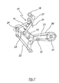
- the bars 28 and 29 are of a different configuration.
- the bars 28 and 29 include longitudinally extending projections 41 and 42 that are not transversely aligned as in the case of the projection 34 and recess 35.
- the projection 42 is located downstream, of the tubular bag material 36, relative to the projection 41.
- the projection 41 deflects the tubular bag material 36 transversely to the normal direction of travel of the tubular bag material 36 and the projection 42 deflects the tubular bag material 36 in the opposite direction.
- the projections 41 and 42 also act to close the tubular bag material 36 as well as deflect it. Accordingly, in this embodiment the projections 41 and 42 provide deflecting and closing members.
- a still further deflecting member 43 can be used.
- the deflecting member 43 is mounted directly on the arm 13 so as to rotate therewith.
- the member 43 engages the tubular bag material 36 in between the deflecting members 41 and 42 and the heads 11 and 12.
- the member 43 is fixed relative to the heads 11 and 12 while the projections 41 and 42 move relative to the heads 11 and 12, when the projections 41 and 42 are engaged with the tubular bag material 36.
- the projections 41 and 42 also act as tube closer bars. They are mounted in a similar manner to the bars 28 and 29.
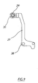
- the tube closer bars 28 and 29 arc each provided with a "C" shaped engagement member 44 or 45, so that each engagement member 44, 45 has a recess 46. Projecting into each recess 46 is a portion of the other engagement member 44, 45. Accordingly, the members 44 and 45 are not transversely aligned relative to the tubular bag material 36, that is, the engagement member 45 is located closer to the heads 11 and 12 than the engagement member 44.
- the engagement member acts as bag material deflecting and closing member.
- the tube closer bars 28 and 29 are of a circular transverse cross section so as not to have any projections or recesses. However, deflection of the tubular bag material 36 is performed by the member 43, as discussed previously.
- a single bag deflection member 43 may be employed with tube closer bars 28 and 29 (not necessarily having the projection 34 and recess 35).
- the bag deflection member 43 being mounted with one of the heads 11 or 12 so as to rotate therewith, but engage the bag material 36 to cause deflection thereof. Accordingly, the bag material deflecting and closing members are provided by the bars 28 and 29, and the member 43. It should be noted that the bars 28 and 29, while being mounted on the supports 21, move angularly relative to the heads 11 and 12 when the bars 28 and 29 are engaged.
- the tubular bag material 36 is deflected from its normal direction of travel by one or more bag material deflecting members.
- the bag material deflecting members are tube close bars 28 and 29 while in another embodiment a bag material deflecting member 43 is employed with a pair of tube closer bars 28 and 29.
- each of the above embodiments includes an assembly 50 which in a first operative configuration allows product to pass along the bag material 36, while in a second operative configuration at least substantially prevents product passing along the bag material past the deflecting members and being located between the jaws 11 and 12.
Landscapes
- Engineering & Computer Science (AREA)
- Mechanical Engineering (AREA)
- Package Closures (AREA)
- Containers And Plastic Fillers For Packaging (AREA)
- Basic Packing Technique (AREA)
- Auxiliary Devices For And Details Of Packaging Control (AREA)
Applications Claiming Priority (2)
| Application Number | Priority Date | Filing Date | Title |
|---|---|---|---|
| AUPR945501 | 2001-12-12 | ||
| AUPR945501 | 2001-12-12 |
Publications (2)
| Publication Number | Publication Date |
|---|---|
| EP1319600A1 EP1319600A1 (en) | 2003-06-18 |
| EP1319600B1 true EP1319600B1 (en) | 2006-08-02 |
Family
ID=3833074
Family Applications (1)
| Application Number | Title | Priority Date | Filing Date |
|---|---|---|---|
| EP02258450A Expired - Lifetime EP1319600B1 (en) | 2001-12-12 | 2002-12-06 | Rotary sealing and stripping assembly for a packaging machine |
Country Status (7)
| Country | Link |
|---|---|
| US (1) | US7159376B2 (sr) |
| EP (1) | EP1319600B1 (sr) |
| JP (1) | JP2003205916A (sr) |
| AT (1) | ATE334886T1 (sr) |
| BR (1) | BR0205246B1 (sr) |
| DE (1) | DE60213545T2 (sr) |
| ES (1) | ES2265477T3 (sr) |
Cited By (1)
| Publication number | Priority date | Publication date | Assignee | Title |
|---|---|---|---|---|
| US11345501B2 (en) | 2018-03-13 | 2022-05-31 | Tna Australia Pty Limited | Packaging machine |
Families Citing this family (15)
| Publication number | Priority date | Publication date | Assignee | Title |
|---|---|---|---|---|
| AU2002315906B2 (en) * | 2001-12-12 | 2008-05-29 | Tna Australia Pty Limited | Rotary Packaging Machines |
| ITMI20050230A1 (it) * | 2005-02-17 | 2006-08-18 | Altopack Spa | Dispositivo di saldatura e taglio trasversale per confezionatrici di materiale sfuso di forma allungata in moto lungo un piano orizzontale |
| EP2181042A4 (en) * | 2007-08-23 | 2013-09-11 | Tna Australia Pty Ltd | PACKAGING MACHINE FOR FLAT BOTTOM BAGS |
| JP5243105B2 (ja) * | 2008-05-23 | 2013-07-24 | 株式会社イシダ | 製袋包装機 |
| ES2428265T3 (es) * | 2008-10-20 | 2013-11-06 | Nestec S.A. | Dispositivos para desinflar sacos y procedimientos para desinflar sacos |
| DE102012004852A1 (de) | 2011-03-17 | 2012-09-20 | Tna Australia Pty Ltd. | Former für eine Verpackungsmaschine |
| AU2012258403B2 (en) | 2011-12-05 | 2016-07-07 | Tna Australia Pty Limited | A former shoulder |
| ITRM20120601A1 (it) | 2011-12-05 | 2013-06-06 | Tna Australia Pty Ltd | Formatore di spalla. |
| ITRM20120599A1 (it) | 2011-12-05 | 2013-06-06 | Tna Australia Pty Ltd | Gruppo di trascinamento del film. |
| AU2013267060C1 (en) | 2012-12-21 | 2017-11-16 | Tna Australia Pty Limited | A packaging machine former |
| AU2014227558B2 (en) | 2013-11-19 | 2018-02-08 | Tna Australia Pty Limited | Sealing jaws for a packaging machine |
| AU2014227559B2 (en) | 2013-11-19 | 2018-02-08 | Tna Australia Pty Limited | A film drive assembly for a packaging machine |
| JP6239957B2 (ja) * | 2013-12-03 | 2017-11-29 | 株式会社イシダ | 製袋包装機および製袋包装システム |
| MX2017010470A (es) | 2016-08-15 | 2018-09-19 | Tna Australia Pty Ltd | Unidad de empaque. |
| ES2663198A1 (es) | 2016-09-12 | 2018-04-11 | Tna Australia Pty Limited | Conducto de conformación |
Family Cites Families (31)
| Publication number | Priority date | Publication date | Assignee | Title |
|---|---|---|---|---|
| US1993442A (en) * | 1933-05-31 | 1935-03-05 | Florence M Greven | Process for packaging dry granular material |
| US2852898A (en) * | 1958-03-05 | 1958-09-23 | Super Valu Stores Inc | Bag filling and sealing machines |
| US3326097A (en) * | 1964-03-30 | 1967-06-20 | West Virginia Pulp & Paper Co | Apparatus for forming tube |
| IT954476B (it) | 1972-04-24 | 1973-08-30 | Dominici Antonio Flli | Procedimento e dispositivo per produrre contenitori d imballaggio riempiti e sigillati |
| GB1444374A (en) * | 1973-08-24 | 1976-07-28 | British Cellophane Ltd | Heat-sealing apparatus |
| CH587751A5 (sr) * | 1975-01-27 | 1977-05-13 | Sig Schweiz Industrieges | |
| US4391081A (en) | 1980-09-08 | 1983-07-05 | Hayssen Manufacturing Company | Method of and apparatus for forming, filling and sealing packages |
| US4532753A (en) | 1983-02-18 | 1985-08-06 | Hayssen Manufacturing Company | Method of and apparatus for forming, filling and sealing packages |
| US4566253A (en) | 1984-05-23 | 1986-01-28 | Kliklok Corporation | Packaging system with interdigitating film advance |
| US4663917A (en) | 1984-06-20 | 1987-05-12 | Taylor Alfred A | Packaging apparatus |
| US4563862A (en) | 1984-10-23 | 1986-01-14 | Kliklok Corporation | Package forming apparatus with combined holding and stripper mechanism |
| JPS62251325A (ja) | 1986-04-18 | 1987-11-02 | 呉羽化学工業株式会社 | 充填包装方法及び装置 |
| US4676051A (en) * | 1986-10-20 | 1987-06-30 | Moore Push-Pin Company | Method and apparatus for forming, filling and sealing bags made from a continuous plastic sheet |
| DE3732033A1 (de) | 1987-09-23 | 1989-04-13 | Rovema Gmbh | Siegelvorrichtung |
| US4922650A (en) * | 1987-12-14 | 1990-05-08 | Kikkoman Corporation | System for manufacturing solid medium |
| JPH07110647B2 (ja) * | 1988-06-28 | 1995-11-29 | 株式会社東京自働機械製作所 | 製袋充填包装装置 |
| US4999974A (en) | 1990-03-26 | 1991-03-19 | Hayssen Manufacturing Company | Method of and apparatus for forming filling and sealing packages |
| JPH07132907A (ja) | 1993-11-04 | 1995-05-23 | Kao Corp | 粉体入り容器の製造方法および製造装置 |
| JP2598879B2 (ja) | 1993-12-20 | 1997-04-09 | オリヒロ株式会社 | 竪型充填包装機 |
| AUPM374694A0 (en) | 1994-02-08 | 1994-03-03 | Taylor, Alfred Alexander | A packaging machine |
| JPH0840403A (ja) | 1994-07-26 | 1996-02-13 | Kao Corp | 粉体充填密封包袋製造方法及び装置 |
| JPH08175523A (ja) | 1994-12-23 | 1996-07-09 | Ishida Co Ltd | 製袋包装機 |
| WO1996032328A1 (en) | 1995-04-01 | 1996-10-17 | Molins Plc | Packaging machine with a stripping device |
| EP0842087B8 (en) * | 1995-06-30 | 2002-12-11 | Kliklok Corporation | Method for feeding products |
| EP0811557A3 (en) | 1996-06-04 | 1998-12-30 | ISHIDA CO., Ltd. | Transverse sealer for a packaging machine |
| JPH11180401A (ja) | 1997-12-24 | 1999-07-06 | Nippon Seiki Co Ltd | 充填包装機及びその制御方法 |
| JPH11321806A (ja) * | 1998-05-11 | 1999-11-24 | Ishida Co Ltd | 製袋包装機 |
| US6052971A (en) | 1998-11-09 | 2000-04-25 | Hayssen, Inc. | Offset stripper and stripping method for vertical form, fill and seal machine |
| JP2000226006A (ja) | 1999-02-03 | 2000-08-15 | Ishida Co Ltd | 連続製袋包装方法、及び製袋包装機 |
| DE29911847U1 (de) * | 1999-07-07 | 2000-11-23 | Vision Verpackungstechnik GmbH, 35305 Grünberg | Einrichtung zum Herstellen von mit Schüttgut gefüllten Schlauchbeuteln |
| US20020092271A1 (en) | 2001-01-18 | 2002-07-18 | Lloyd Kovacs | Finishing assembly and method for a vertical form, fill and seal machine |
-
2002
- 2002-12-06 ES ES02258450T patent/ES2265477T3/es not_active Expired - Lifetime
- 2002-12-06 AT AT02258450T patent/ATE334886T1/de not_active IP Right Cessation
- 2002-12-06 EP EP02258450A patent/EP1319600B1/en not_active Expired - Lifetime
- 2002-12-06 DE DE60213545T patent/DE60213545T2/de not_active Expired - Lifetime
- 2002-12-11 US US10/317,848 patent/US7159376B2/en not_active Expired - Lifetime
- 2002-12-11 BR BRPI0205246-6A patent/BR0205246B1/pt not_active IP Right Cessation
- 2002-12-12 JP JP2002360870A patent/JP2003205916A/ja active Pending
Cited By (1)
| Publication number | Priority date | Publication date | Assignee | Title |
|---|---|---|---|---|
| US11345501B2 (en) | 2018-03-13 | 2022-05-31 | Tna Australia Pty Limited | Packaging machine |
Also Published As
| Publication number | Publication date |
|---|---|
| ATE334886T1 (de) | 2006-08-15 |
| BR0205246A (pt) | 2004-07-20 |
| US20030136092A1 (en) | 2003-07-24 |
| ES2265477T3 (es) | 2007-02-16 |
| DE60213545D1 (de) | 2006-09-14 |
| JP2003205916A (ja) | 2003-07-22 |
| BR0205246B1 (pt) | 2011-04-05 |
| US7159376B2 (en) | 2007-01-09 |
| EP1319600A1 (en) | 2003-06-18 |
| DE60213545T2 (de) | 2007-08-09 |
Similar Documents
| Publication | Publication Date | Title |
|---|---|---|
| EP1319600B1 (en) | Rotary sealing and stripping assembly for a packaging machine | |
| US4663917A (en) | Packaging apparatus | |
| EP0666215B1 (en) | Stripper for pacaging machines | |
| US7451582B2 (en) | Clip machine | |
| US20050150188A1 (en) | Modular shrink-wrap machine | |
| US7076936B2 (en) | Film delivery unit for shrink wrap packaging system | |
| US20080066430A1 (en) | Continuous motion drive mechanism for a form, fill, and seal machine | |
| CN114007940B (zh) | 用于对纸卷进行包装的包装机器 | |
| US20100199614A1 (en) | Packaging machine for block bottom bags | |
| AU2002315906B2 (en) | Rotary Packaging Machines | |
| EP0999136A1 (en) | Packaging machine | |
| CN100478256C (zh) | 馈送包装材料纸带并切割成多段用的装置 | |
| EP0861785B1 (en) | Poker for unblocking the filling nozzle of a packaging machine | |
| EP4212316A1 (en) | A transverse welding and cutting assembly for a flow-pack packaging machine | |
| JP2009143620A (ja) | 自動充填包装装置 | |
| CA1266793A (en) | Bottom seal bag making machine | |
| EP1778548B1 (en) | Sealing and transversal cutting device for loose product packaging systems | |
| US3626797A (en) | Synchronous cutter mechanism | |
| US20140000216A1 (en) | Clipping machine | |
| EP1609720B1 (en) | Tubular bag making machine for the formation of bags with lateral shaping edges | |
| CN1648004A (zh) | 产生管状包装的方法和装置 | |
| US20080163589A1 (en) | Combined packaging machine | |
| AU686283B2 (en) | A packaging machine | |
| JP2010514630A (ja) | 独立した切断バー及び溶着バーを備えた包装機械 | |
| GB1590317A (en) | Machine for making bags from plastics material |
Legal Events
| Date | Code | Title | Description |
|---|---|---|---|
| PUAI | Public reference made under article 153(3) epc to a published international application that has entered the european phase |
Free format text: ORIGINAL CODE: 0009012 |
|
| AK | Designated contracting states |
Designated state(s): AT BE BG CH CY CZ DE DK EE ES FI FR GB GR IE IT LI LU MC NL PT SE SI SK TR |
|
| AX | Request for extension of the european patent |
Extension state: AL LT LV MK RO |
|
| 17P | Request for examination filed |
Effective date: 20030929 |
|
| 17Q | First examination report despatched |
Effective date: 20031126 |
|
| AKX | Designation fees paid |
Designated state(s): AT BE BG CH CY CZ DE DK EE ES FI FR GB GR IE IT LI LU MC NL PT SE SI SK TR |
|
| GRAP | Despatch of communication of intention to grant a patent |
Free format text: ORIGINAL CODE: EPIDOSNIGR1 |
|
| RIN1 | Information on inventor provided before grant (corrected) |
Inventor name: TAYLOR, ALFRED ALEXANDER |
|
| GRAS | Grant fee paid |
Free format text: ORIGINAL CODE: EPIDOSNIGR3 |
|
| GRAA | (expected) grant |
Free format text: ORIGINAL CODE: 0009210 |
|
| AK | Designated contracting states |
Kind code of ref document: B1 Designated state(s): AT BE BG CH CY CZ DE DK EE ES FI FR GB GR IE IT LI LU MC NL PT SE SI SK TR |
|
| PG25 | Lapsed in a contracting state [announced via postgrant information from national office to epo] |
Ref country code: SK Free format text: LAPSE BECAUSE OF FAILURE TO SUBMIT A TRANSLATION OF THE DESCRIPTION OR TO PAY THE FEE WITHIN THE PRESCRIBED TIME-LIMIT Effective date: 20060802 Ref country code: SI Free format text: LAPSE BECAUSE OF FAILURE TO SUBMIT A TRANSLATION OF THE DESCRIPTION OR TO PAY THE FEE WITHIN THE PRESCRIBED TIME-LIMIT Effective date: 20060802 Ref country code: LI Free format text: LAPSE BECAUSE OF FAILURE TO SUBMIT A TRANSLATION OF THE DESCRIPTION OR TO PAY THE FEE WITHIN THE PRESCRIBED TIME-LIMIT Effective date: 20060802 Ref country code: FI Free format text: LAPSE BECAUSE OF FAILURE TO SUBMIT A TRANSLATION OF THE DESCRIPTION OR TO PAY THE FEE WITHIN THE PRESCRIBED TIME-LIMIT Effective date: 20060802 Ref country code: CZ Free format text: LAPSE BECAUSE OF FAILURE TO SUBMIT A TRANSLATION OF THE DESCRIPTION OR TO PAY THE FEE WITHIN THE PRESCRIBED TIME-LIMIT Effective date: 20060802 Ref country code: CH Free format text: LAPSE BECAUSE OF FAILURE TO SUBMIT A TRANSLATION OF THE DESCRIPTION OR TO PAY THE FEE WITHIN THE PRESCRIBED TIME-LIMIT Effective date: 20060802 Ref country code: BE Free format text: LAPSE BECAUSE OF FAILURE TO SUBMIT A TRANSLATION OF THE DESCRIPTION OR TO PAY THE FEE WITHIN THE PRESCRIBED TIME-LIMIT Effective date: 20060802 Ref country code: AT Free format text: LAPSE BECAUSE OF FAILURE TO SUBMIT A TRANSLATION OF THE DESCRIPTION OR TO PAY THE FEE WITHIN THE PRESCRIBED TIME-LIMIT Effective date: 20060802 |
|
| REG | Reference to a national code |
Ref country code: GB Ref legal event code: FG4D |
|
| REG | Reference to a national code |
Ref country code: CH Ref legal event code: EP |
|
| REG | Reference to a national code |
Ref country code: IE Ref legal event code: FG4D |
|
| REF | Corresponds to: |
Ref document number: 60213545 Country of ref document: DE Date of ref document: 20060914 Kind code of ref document: P |
|
| PG25 | Lapsed in a contracting state [announced via postgrant information from national office to epo] |
Ref country code: SE Free format text: LAPSE BECAUSE OF FAILURE TO SUBMIT A TRANSLATION OF THE DESCRIPTION OR TO PAY THE FEE WITHIN THE PRESCRIBED TIME-LIMIT Effective date: 20061102 Ref country code: DK Free format text: LAPSE BECAUSE OF FAILURE TO SUBMIT A TRANSLATION OF THE DESCRIPTION OR TO PAY THE FEE WITHIN THE PRESCRIBED TIME-LIMIT Effective date: 20061102 Ref country code: BG Free format text: LAPSE BECAUSE OF FAILURE TO SUBMIT A TRANSLATION OF THE DESCRIPTION OR TO PAY THE FEE WITHIN THE PRESCRIBED TIME-LIMIT Effective date: 20061102 |
|
| PGFP | Annual fee paid to national office [announced via postgrant information from national office to epo] |
Ref country code: MC Payment date: 20061128 Year of fee payment: 5 |
|
| PGFP | Annual fee paid to national office [announced via postgrant information from national office to epo] |
Ref country code: FR Payment date: 20061208 Year of fee payment: 5 |
|
| PGFP | Annual fee paid to national office [announced via postgrant information from national office to epo] |
Ref country code: LU Payment date: 20061211 Year of fee payment: 5 |
|
| PGFP | Annual fee paid to national office [announced via postgrant information from national office to epo] |
Ref country code: IE Payment date: 20061213 Year of fee payment: 5 |
|
| PG25 | Lapsed in a contracting state [announced via postgrant information from national office to epo] |
Ref country code: PT Free format text: LAPSE BECAUSE OF FAILURE TO SUBMIT A TRANSLATION OF THE DESCRIPTION OR TO PAY THE FEE WITHIN THE PRESCRIBED TIME-LIMIT Effective date: 20070102 |
|
| REG | Reference to a national code |
Ref country code: CH Ref legal event code: PL |
|
| REG | Reference to a national code |
Ref country code: ES Ref legal event code: FG2A Ref document number: 2265477 Country of ref document: ES Kind code of ref document: T3 |
|
| EN | Fr: translation not filed | ||
| PLBE | No opposition filed within time limit |
Free format text: ORIGINAL CODE: 0009261 |
|
| STAA | Information on the status of an ep patent application or granted ep patent |
Free format text: STATUS: NO OPPOSITION FILED WITHIN TIME LIMIT |
|
| 26N | No opposition filed |
Effective date: 20070503 |
|
| PG25 | Lapsed in a contracting state [announced via postgrant information from national office to epo] |
Ref country code: GR Free format text: LAPSE BECAUSE OF FAILURE TO SUBMIT A TRANSLATION OF THE DESCRIPTION OR TO PAY THE FEE WITHIN THE PRESCRIBED TIME-LIMIT Effective date: 20061103 Ref country code: FR Free format text: LAPSE BECAUSE OF FAILURE TO SUBMIT A TRANSLATION OF THE DESCRIPTION OR TO PAY THE FEE WITHIN THE PRESCRIBED TIME-LIMIT Effective date: 20070511 |
|
| PG25 | Lapsed in a contracting state [announced via postgrant information from national office to epo] |
Ref country code: EE Free format text: LAPSE BECAUSE OF FAILURE TO SUBMIT A TRANSLATION OF THE DESCRIPTION OR TO PAY THE FEE WITHIN THE PRESCRIBED TIME-LIMIT Effective date: 20060802 |
|
| PG25 | Lapsed in a contracting state [announced via postgrant information from national office to epo] |
Ref country code: TR Free format text: LAPSE BECAUSE OF FAILURE TO SUBMIT A TRANSLATION OF THE DESCRIPTION OR TO PAY THE FEE WITHIN THE PRESCRIBED TIME-LIMIT Effective date: 20060802 Ref country code: MC Free format text: LAPSE BECAUSE OF NON-PAYMENT OF DUE FEES Effective date: 20071231 |
|
| PG25 | Lapsed in a contracting state [announced via postgrant information from national office to epo] |
Ref country code: IE Free format text: LAPSE BECAUSE OF NON-PAYMENT OF DUE FEES Effective date: 20071206 |
|
| PG25 | Lapsed in a contracting state [announced via postgrant information from national office to epo] |
Ref country code: CY Free format text: LAPSE BECAUSE OF FAILURE TO SUBMIT A TRANSLATION OF THE DESCRIPTION OR TO PAY THE FEE WITHIN THE PRESCRIBED TIME-LIMIT Effective date: 20060802 |
|
| PG25 | Lapsed in a contracting state [announced via postgrant information from national office to epo] |
Ref country code: LU Free format text: LAPSE BECAUSE OF NON-PAYMENT OF DUE FEES Effective date: 20071206 |
|
| PGFP | Annual fee paid to national office [announced via postgrant information from national office to epo] |
Ref country code: NL Payment date: 20191212 Year of fee payment: 18 Ref country code: DE Payment date: 20191203 Year of fee payment: 18 |
|
| PGFP | Annual fee paid to national office [announced via postgrant information from national office to epo] |
Ref country code: IT Payment date: 20191209 Year of fee payment: 18 |
|
| PGFP | Annual fee paid to national office [announced via postgrant information from national office to epo] |
Ref country code: ES Payment date: 20200102 Year of fee payment: 18 Ref country code: GB Payment date: 20191206 Year of fee payment: 18 |
|
| REG | Reference to a national code |
Ref country code: DE Ref legal event code: R119 Ref document number: 60213545 Country of ref document: DE |
|
| REG | Reference to a national code |
Ref country code: NL Ref legal event code: MM Effective date: 20210101 |
|
| GBPC | Gb: european patent ceased through non-payment of renewal fee |
Effective date: 20201206 |
|
| PG25 | Lapsed in a contracting state [announced via postgrant information from national office to epo] |
Ref country code: NL Free format text: LAPSE BECAUSE OF NON-PAYMENT OF DUE FEES Effective date: 20210101 |
|
| PG25 | Lapsed in a contracting state [announced via postgrant information from national office to epo] |
Ref country code: IT Free format text: LAPSE BECAUSE OF NON-PAYMENT OF DUE FEES Effective date: 20201206 |
|
| PG25 | Lapsed in a contracting state [announced via postgrant information from national office to epo] |
Ref country code: DE Free format text: LAPSE BECAUSE OF NON-PAYMENT OF DUE FEES Effective date: 20210701 Ref country code: GB Free format text: LAPSE BECAUSE OF NON-PAYMENT OF DUE FEES Effective date: 20201206 |
|
| REG | Reference to a national code |
Ref country code: ES Ref legal event code: FD2A Effective date: 20220208 |
|
| PG25 | Lapsed in a contracting state [announced via postgrant information from national office to epo] |
Ref country code: ES Free format text: LAPSE BECAUSE OF NON-PAYMENT OF DUE FEES Effective date: 20201207 |