EP1319483A2 - Zylinderkopfbohrer oder ähnliches Werkzeug mit Hartmetallschneiden - Google Patents
Zylinderkopfbohrer oder ähnliches Werkzeug mit Hartmetallschneiden Download PDFInfo
- Publication number
- EP1319483A2 EP1319483A2 EP02027397A EP02027397A EP1319483A2 EP 1319483 A2 EP1319483 A2 EP 1319483A2 EP 02027397 A EP02027397 A EP 02027397A EP 02027397 A EP02027397 A EP 02027397A EP 1319483 A2 EP1319483 A2 EP 1319483A2
- Authority
- EP
- European Patent Office
- Prior art keywords
- head
- shaft
- drill
- hard metal
- support part
- Prior art date
- Legal status (The legal status is an assumption and is not a legal conclusion. Google has not performed a legal analysis and makes no representation as to the accuracy of the status listed.)
- Granted
Links
Images

Classifications
-
- B—PERFORMING OPERATIONS; TRANSPORTING
- B27—WORKING OR PRESERVING WOOD OR SIMILAR MATERIAL; NAILING OR STAPLING MACHINES IN GENERAL
- B27G—ACCESSORY MACHINES OR APPARATUS FOR WORKING WOOD OR SIMILAR MATERIALS; TOOLS FOR WORKING WOOD OR SIMILAR MATERIALS; SAFETY DEVICES FOR WOOD WORKING MACHINES OR TOOLS
- B27G15/00—Boring or turning tools; Augers
-
- Y—GENERAL TAGGING OF NEW TECHNOLOGICAL DEVELOPMENTS; GENERAL TAGGING OF CROSS-SECTIONAL TECHNOLOGIES SPANNING OVER SEVERAL SECTIONS OF THE IPC; TECHNICAL SUBJECTS COVERED BY FORMER USPC CROSS-REFERENCE ART COLLECTIONS [XRACs] AND DIGESTS
- Y10—TECHNICAL SUBJECTS COVERED BY FORMER USPC
- Y10S—TECHNICAL SUBJECTS COVERED BY FORMER USPC CROSS-REFERENCE ART COLLECTIONS [XRACs] AND DIGESTS
- Y10S408/00—Cutting by use of rotating axially moving tool
- Y10S408/713—Tool having detachable cutting edge
-
- Y—GENERAL TAGGING OF NEW TECHNOLOGICAL DEVELOPMENTS; GENERAL TAGGING OF CROSS-SECTIONAL TECHNOLOGIES SPANNING OVER SEVERAL SECTIONS OF THE IPC; TECHNICAL SUBJECTS COVERED BY FORMER USPC CROSS-REFERENCE ART COLLECTIONS [XRACs] AND DIGESTS
- Y10—TECHNICAL SUBJECTS COVERED BY FORMER USPC
- Y10T—TECHNICAL SUBJECTS COVERED BY FORMER US CLASSIFICATION
- Y10T408/00—Cutting by use of rotating axially moving tool
- Y10T408/78—Tool of specific diverse material
-
- Y—GENERAL TAGGING OF NEW TECHNOLOGICAL DEVELOPMENTS; GENERAL TAGGING OF CROSS-SECTIONAL TECHNOLOGIES SPANNING OVER SEVERAL SECTIONS OF THE IPC; TECHNICAL SUBJECTS COVERED BY FORMER USPC CROSS-REFERENCE ART COLLECTIONS [XRACs] AND DIGESTS
- Y10—TECHNICAL SUBJECTS COVERED BY FORMER USPC
- Y10T—TECHNICAL SUBJECTS COVERED BY FORMER US CLASSIFICATION
- Y10T408/00—Cutting by use of rotating axially moving tool
- Y10T408/89—Tool or Tool with support
- Y10T408/907—Tool or Tool with support including detailed shank
-
- Y—GENERAL TAGGING OF NEW TECHNOLOGICAL DEVELOPMENTS; GENERAL TAGGING OF CROSS-SECTIONAL TECHNOLOGIES SPANNING OVER SEVERAL SECTIONS OF THE IPC; TECHNICAL SUBJECTS COVERED BY FORMER USPC CROSS-REFERENCE ART COLLECTIONS [XRACs] AND DIGESTS
- Y10—TECHNICAL SUBJECTS COVERED BY FORMER USPC
- Y10T—TECHNICAL SUBJECTS COVERED BY FORMER US CLASSIFICATION
- Y10T408/00—Cutting by use of rotating axially moving tool
- Y10T408/89—Tool or Tool with support
- Y10T408/909—Having peripherally spaced cutting edges
- Y10T408/9098—Having peripherally spaced cutting edges with means to retain Tool to support
Definitions
- the invention relates to a cylinder head drill with carbide cutting edges.
- Carbide cutting are desirable or necessary because drilling e.g. in the manufacture of Furniture parts, usually made in resin-bonded particle board, so that Tools made of tool steels without carbide cutting are only unsatisfactory Reach service life.
- the object of the invention is therefore a cylinder head drill or a similar tool To be trained so that it is inexpensive in quantities with the least possible effort is producible, but achieves the necessary precision.
- the concept according to the invention thus consists of the entire head of the cylinder head drill or tool made of hard metal, namely by injection molding using hard metal powder mixed with a wax as a plasticizer, and sintering the injection molded green blank while the stem is molded Head support part is made of tool steel.
- the carbide head and the Head support part of the shaft are with interlocking interlocking elements trained both centering the head with respect to the shaft when Placing the head on the shaft as well as a positive connection in the circumferential direction manufacture so that on the one hand also the correct rotational position of the head with respect to the shaft is ensured during assembly as well as when using the cylinder head drill the head is positively carried along by the shaft.
- the connection of head and shaft by soldering or welding can then be done without any special Effort.
- the cylinder head drill according to the invention consists of a shaft 1 (FIG. 1) and a head 2 placed thereon (FIGS. 2 and 3).
- the shaft 1 consists of a shaft part 11 with a molded-on front Head support part 12, which comprises two radial arms 13, which are approximately disc-shaped.
- the head support part 12 has two axial surface projections on its upper end face 14 15, namely one on each radial arm 13.
- the head support part 12 instructs a central countersink 16 on its end face 14.
- the shaft part 11 is cylindrical in the usual way and serves to clamp the Cylinder head drill.
- the shaft 1 is made entirely of tool steel.
- the head 2 which is made in one piece and overall from hard metal is, namely by injection molding with a serving as a plasticizer and binder Wax mixed carbide powder, and sintering the blank thus produced, whereby the wax is driven out completely.
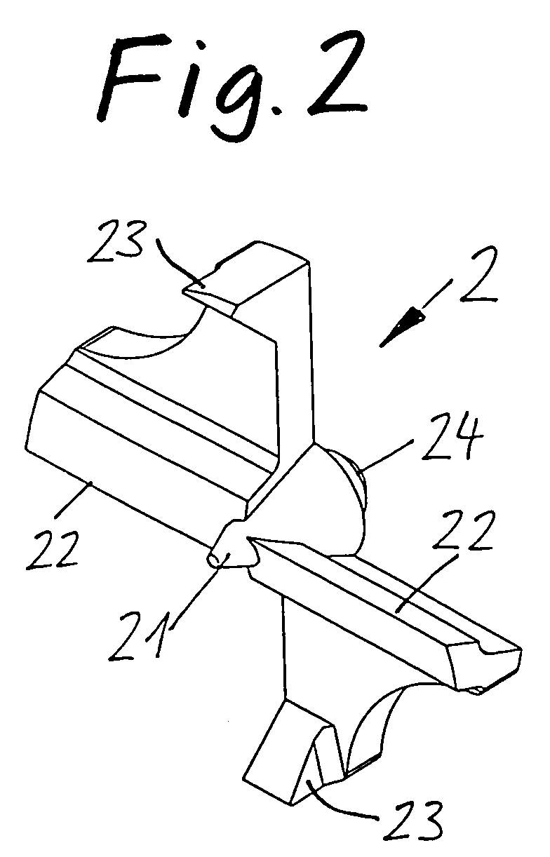
- the head 2 has a central drilling centering tip 21 on its upper side, further two of them opposite approximately radially extending main cutting edges 22 and two to each roughly 23 pre-cut for a circumferential pre-cut on.
- This cutting configuration is basically common in itself.
- the head On its underside (Fig. 3), the head has a central pin 24 which in the central countersink 16 of the shaft 1 fits.
- the head 2 On the undersides of it two diametrically opposed disk sector areas, on which the Cutting edges 22, 23 are formed, each with a recess 25 in the form of a flat Provide depression. These shallow depressions 25 are each exactly complementary to the surface projections 15 of the head support part 12 of the shaft 1 are formed.
- the head 2 can thus be placed on the head support part 12 of the shaft 1, the Pin 24 engages on the underside of the head as a centering pin in the countersink 16 of the shaft and the surface projections 15 on the head support part 12 of the shaft 1 into the flat ones Engage recesses 25 on the underside of the head.
- This will refer to the head the shaft is positioned exactly in the center and in the correct rotational position and can be done in a simple Process to be welded or soldered to the shaft without the need for devices necessary to establish and maintain the exact relative positioning are.
- this positive connection enables the transmission of the working torque from the shaft to the head so that this power transmission does not have the Solder or weld connection must be transferred.
Landscapes
- Life Sciences & Earth Sciences (AREA)
- Engineering & Computer Science (AREA)
- Mechanical Engineering (AREA)
- Wood Science & Technology (AREA)
- Forests & Forestry (AREA)
- Drilling Tools (AREA)
- Earth Drilling (AREA)
- Powder Metallurgy (AREA)
- Milling Processes (AREA)
Abstract
Description
- Fig. 1
- den Schaft mit Kopfträgerteil in perspektivi-scher Darstellung,
- Fig. 2
- den Kopf in perspektivischer Darstellung auf seine Oberseite gesehen, und
- Fig. 3
- den Kopf in perspektivischer Darstellung auf eine Unterseite gesehen.
Claims (4)
- Zylinderkopfbohrer oder ähnliches Werkzeug, das einen mit Hartmetallschneiden, (22, 23) versehenen Kopf (2) und einen Schaft (1) zum Einspannen aufweist, dadurch gekennzeichnet, dass Schaft (1) und Kopf (2) als gesonderte, stoffschlüssig miteinander verbundene Bauteile ausgebildet sind,
wobei der Kopf (2) vollständig als Sinterkörper aus Hartmetall ausgebildet ist,
dass weiter der Schaft (1) mit einem Kopfträgerteil (12) ausgebildet ist, auf welches der Kopf (2) stirnseitig aufgesetzt ist,
und dass der Kopfträgerteil (12) des Schafts (1) und der Kopf (2) mit miteinander zusammenwirkenden Formschlusselementen (15, 16, 24, 25) versehen sind, die den Kopf mit Bezug auf den Schaft sowohl zentrieren (16, 24) als auch drehpositionsmäßig positionieren (15, 25). - Zylinderkopfbohrer bzw. Werkzeug nach Anspruch 1, dadurch gekennzeichnet, dass die Formschlußelemente zum Zentrieren einen Zentrierzapfen (24) am einen der Teile Schaft (1) und Kopf (2) und eine Senkbohrung (16) am jeweils anderen Teil aufweisen.
- Zylinderkopfbohrer bzw. Werkzeug nach Anspruch 1 oder 2, wobei die Formschlusselemente zur drehpositionsmäßigen Positionierung miteinander zusammenwirkende Flächenvorsprünge 15 und dazu komplementäre flache Vertiefungen (25) an den beiden Teilen Schafft (1) und Kopf (2) aufweisen, die zueinander komplementär ausgebildet sind.
- Zylinderkopfbohrer bzw. Werkzeug nach Anspruch 3, dadurch gekennzeichnet, dass der Schaftträgerteil (12) des Schafts (1) plattenartige Elemente (13) aufweist, an denen die Flächenvorsprünge (15) gebildet sind, und dass die komplementären flachen Vertiefungen (25) an der Kopfunterseite gebildet sind.
Applications Claiming Priority (2)
| Application Number | Priority Date | Filing Date | Title |
|---|---|---|---|
| DE10161823 | 2001-12-15 | ||
| DE10161823A DE10161823A1 (de) | 2001-12-15 | 2001-12-15 | Zylinderkopfbohrer oder ähnliches Werkzeug mit Hartmetallschneiden |
Publications (3)
| Publication Number | Publication Date |
|---|---|
| EP1319483A2 true EP1319483A2 (de) | 2003-06-18 |
| EP1319483A3 EP1319483A3 (de) | 2005-02-02 |
| EP1319483B1 EP1319483B1 (de) | 2007-08-08 |
Family
ID=7709449
Family Applications (1)
| Application Number | Title | Priority Date | Filing Date |
|---|---|---|---|
| EP02027397A Expired - Lifetime EP1319483B1 (de) | 2001-12-15 | 2002-12-09 | Zylinderkopfbohrer mit Hartmetallschneiden |
Country Status (8)
| Country | Link |
|---|---|
| US (1) | US6986627B2 (de) |
| EP (1) | EP1319483B1 (de) |
| AT (1) | ATE369239T1 (de) |
| CA (1) | CA2414252C (de) |
| DE (2) | DE10161823A1 (de) |
| DK (1) | DK1319483T3 (de) |
| ES (1) | ES2290237T3 (de) |
| PT (1) | PT1319483E (de) |
Cited By (4)
| Publication number | Priority date | Publication date | Assignee | Title |
|---|---|---|---|---|
| WO2009121595A3 (de) * | 2008-04-03 | 2010-03-18 | Kennametal Inc. | Drehwerkzeug, insbesondere bohrwerkzeug |
| EP1990154A3 (de) * | 2007-05-11 | 2013-06-05 | BOEHLERIT GmbH & Co.KG. | Schneidwerkzeug |
| WO2014018235A3 (en) * | 2012-07-26 | 2014-03-20 | TDY Industries, LLC | Composite sintered powder metal articles |
| US8790439B2 (en) | 2008-06-02 | 2014-07-29 | Kennametal Inc. | Composite sintered powder metal articles |
Families Citing this family (6)
| Publication number | Priority date | Publication date | Assignee | Title |
|---|---|---|---|---|
| US6290728B1 (en) * | 1998-09-10 | 2001-09-18 | Percardia, Inc. | Designs for left ventricular conduit |
| US7150589B2 (en) * | 2003-10-01 | 2006-12-19 | Greenlee Textron Inc. | Deburring tool |
| US8235080B2 (en) * | 2008-11-17 | 2012-08-07 | Lee Valley Tools, Ltd. | Interlocking, adjustable edge-forming router bit |
| USD649569S1 (en) | 2009-09-10 | 2011-11-29 | Techtronic Power Tools Technology Limited | Wood boring bit |
| US8727679B2 (en) * | 2009-09-10 | 2014-05-20 | Techtronic Power Tools Technology Limited | Wood boring bit |
| US10835969B1 (en) | 2018-06-29 | 2020-11-17 | Andrew James Scaglione | Self-aligning counter bore cutting tool and method of operation |
Family Cites Families (19)
| Publication number | Priority date | Publication date | Assignee | Title |
|---|---|---|---|---|
| DE331207C (de) * | 1921-08-29 | 1921-01-04 | Rudolf Cerotzky | Vorrichtung fuer Bohrmaschinen und Drehbaenke zum Ausbohren von Loechern |
| US2259611A (en) * | 1941-03-19 | 1941-10-21 | George M Burger | Drill |
| DE2010291A1 (de) | 1970-03-05 | 1971-09-23 | Robert Bosch Gmbh, 7000 Stuttgart | Steuerung von Ein- und Auslaßventilen bei Brennkraftmaschinen durch Flüssigkeit |
| US4160616A (en) * | 1977-10-03 | 1979-07-10 | Winblad Michael E | Drill containing minimum cutting material |
| DE3309860A1 (de) * | 1983-02-08 | 1984-08-09 | Fa. Gottlieb Gühring, 7470 Albstadt | Bohrwerkzeug |
| US4580934A (en) * | 1983-12-12 | 1986-04-08 | Mccormick Wallace W | Hole sizing tool |
| US4762445A (en) * | 1985-06-03 | 1988-08-09 | Precorp, Inc. | Composite sintered twist drill |
| DE8808954U1 (de) * | 1987-06-15 | 1988-09-22 | Gustav Weber Schlagringwerkzeug-Fabrik, 5600 Wuppertal | Bohrer |
| DE9206657U1 (de) * | 1992-05-15 | 1993-09-16 | Töpfer, Rainer, 28870 Ottersberg | Rotationswerkzeug mit Hartmetalleinsätzen |
| US5399051A (en) * | 1993-08-02 | 1995-03-21 | Aken; Douglas G. | Interchangeable head boring or driving apparatus |
| WO1996027469A1 (de) * | 1995-03-03 | 1996-09-12 | Komet Präzisionswerkzeuge Robert Breuning Gmbh | Bohrwerkzeug |
| DE19543233A1 (de) * | 1995-11-07 | 1997-05-15 | Johne & Co Praezisionswerkzeug | Bohrwerkzeug mit auswechselbarer Spitze |
| IL120948A0 (en) * | 1997-05-29 | 1997-09-30 | Iscar Ltd | Cutting tool assembly |
| DE19832551A1 (de) * | 1998-07-21 | 2000-01-27 | Tigra Hartstoff Gmbh | Schaftfräser mit Hartmetallschneiden |
| DE10009721A1 (de) * | 2000-03-01 | 2001-09-06 | Komet Stahlhalter Werkzeuge | Maschinenreibahle und Reibkopf für eine Maschinenreibahle |
| AT4227U1 (de) * | 2000-03-03 | 2001-04-25 | Johann Eberhard Ges M B H | Bohrer |
| DE10013738A1 (de) * | 2000-03-20 | 2001-10-11 | Tigra Hartstoff Gmbh | Zylinderbohrer mit Hartmetallschneiden |
| DE20102914U1 (de) * | 2001-02-19 | 2001-05-03 | Berner GmbH, 74653 Künzelsau | Bohrer mit Bohrkopf aus Hartmetall |
| US6499919B2 (en) * | 2001-03-27 | 2002-12-31 | Tigra Harlstoff Gmbh | Cylindrical bit with hard metal cutting edges |
-
2001
- 2001-12-15 DE DE10161823A patent/DE10161823A1/de not_active Withdrawn
-
2002
- 2002-12-09 EP EP02027397A patent/EP1319483B1/de not_active Expired - Lifetime
- 2002-12-09 DK DK02027397T patent/DK1319483T3/da active
- 2002-12-09 AT AT02027397T patent/ATE369239T1/de active
- 2002-12-09 ES ES02027397T patent/ES2290237T3/es not_active Expired - Lifetime
- 2002-12-09 PT PT02027397T patent/PT1319483E/pt unknown
- 2002-12-09 DE DE50210633T patent/DE50210633D1/de not_active Expired - Lifetime
- 2002-12-13 CA CA2414252A patent/CA2414252C/en not_active Expired - Fee Related
- 2002-12-13 US US10/320,357 patent/US6986627B2/en not_active Expired - Fee Related
Cited By (7)
| Publication number | Priority date | Publication date | Assignee | Title |
|---|---|---|---|---|
| EP1990154A3 (de) * | 2007-05-11 | 2013-06-05 | BOEHLERIT GmbH & Co.KG. | Schneidwerkzeug |
| WO2009121595A3 (de) * | 2008-04-03 | 2010-03-18 | Kennametal Inc. | Drehwerkzeug, insbesondere bohrwerkzeug |
| KR101255670B1 (ko) * | 2008-04-03 | 2013-04-17 | 케나메탈 아이엔씨. | 기계 가공을 위한 회전 공구 |
| KR101255567B1 (ko) * | 2008-04-03 | 2013-04-23 | 케나메탈 아이엔씨. | 멀티-피스 보링 공구 |
| US8790439B2 (en) | 2008-06-02 | 2014-07-29 | Kennametal Inc. | Composite sintered powder metal articles |
| WO2014018235A3 (en) * | 2012-07-26 | 2014-03-20 | TDY Industries, LLC | Composite sintered powder metal articles |
| CN104582876A (zh) * | 2012-07-26 | 2015-04-29 | 钴碳化钨硬质合金公司 | 烧结粉末金属复合材料制品 |
Also Published As
| Publication number | Publication date |
|---|---|
| ATE369239T1 (de) | 2007-08-15 |
| DE50210633D1 (de) | 2007-09-20 |
| ES2290237T3 (es) | 2008-02-16 |
| DE10161823A1 (de) | 2003-06-26 |
| CA2414252C (en) | 2011-08-23 |
| PT1319483E (pt) | 2007-10-17 |
| EP1319483A3 (de) | 2005-02-02 |
| CA2414252A1 (en) | 2003-06-15 |
| DK1319483T3 (da) | 2007-12-03 |
| US6986627B2 (en) | 2006-01-17 |
| EP1319483B1 (de) | 2007-08-08 |
| US20030118415A1 (en) | 2003-06-26 |
Similar Documents
| Publication | Publication Date | Title |
|---|---|---|
| EP0813459B1 (de) | Bohrwerkzeug | |
| DE3105268C2 (de) | ||
| DE60025810T2 (de) | Bohrer | |
| DE102011012144B4 (de) | Werkzeughalter sowie Werkzeugsystem mit einem Werkzeughalter und einem Werkzeug | |
| EP0142611B1 (de) | Bohrwerkzeug zur Herstellung von Hinterschneidungen in vorgefertigten Bohrungen | |
| EP3898049A1 (de) | Bearbeitungssegment für ein bearbeitungswerkzeug | |
| DE19810192A1 (de) | Bohrwerkzeug | |
| EP1943409B1 (de) | Rundschaftmeissel mit meisselhalter | |
| AT4227U1 (de) | Bohrer | |
| EP1319483B1 (de) | Zylinderkopfbohrer mit Hartmetallschneiden | |
| EP1083294B1 (de) | Bohrwerkzeug | |
| DE102004022747A1 (de) | Spanwerkzeug mit geometrisch bestimmten Schneiden für Drehantrieb | |
| DE2917664C2 (de) | Drehbohrmeißel für Tiefbohrungen | |
| DE69610820T2 (de) | Topfschleifscheibe und schleifscheibenhalter | |
| DE346689C (de) | Als Bohr- und Fraeskopf verwendbares rotierendes Schneidwerkzeug | |
| DE3705717A1 (de) | Dosensenker oder hohlbohrkrone sowie herstellungsverfahren hierfuer | |
| EP0775546B1 (de) | Werkzeughaltevorrichtung | |
| EP3659748B1 (de) | Trägerkörper für ein schleif- oder ein schneidwerkzeug | |
| EP4015108A1 (de) | Verfahren zur herstellung eines bearbeitungssegmentes | |
| DE19545084C1 (de) | Drehantreibbares Werkzeug | |
| EP1136209A2 (de) | Zylinderbohrer mit Hartmetallschneiden | |
| DE3615940A1 (de) | Verfahren zum einbringen tiefer loecher in ein werkstueck | |
| DE3909077C2 (de) | Fräsbohrwerkzeug mit einem Schaft zur Herstellung von kreisrunden Ausnehmungen in Vollmaterial | |
| EP1520647A1 (de) | Elektrodenfräskopf und Flankenfräsmesser | |
| DE202005020931U1 (de) | Bohrer für metallische Werkstoffe |
Legal Events
| Date | Code | Title | Description |
|---|---|---|---|
| PUAI | Public reference made under article 153(3) epc to a published international application that has entered the european phase |
Free format text: ORIGINAL CODE: 0009012 |
|
| AK | Designated contracting states |
Designated state(s): AT BE BG CH CY CZ DE DK EE ES FI FR GB GR IE IT LI LU MC NL PT SE SI SK TR |
|
| AX | Request for extension of the european patent |
Extension state: AL LT LV MK RO |
|
| PUAL | Search report despatched |
Free format text: ORIGINAL CODE: 0009013 |
|
| AK | Designated contracting states |
Kind code of ref document: A3 Designated state(s): AT BE BG CH CY CZ DE DK EE ES FI FR GB GR IE IT LI LU MC NL PT SE SI SK TR |
|
| AX | Request for extension of the european patent |
Extension state: AL LT LV MK RO |
|
| RIC1 | Information provided on ipc code assigned before grant |
Ipc: 7B 23B 51/00 B Ipc: 7B 27G 15/00 A |
|
| 17P | Request for examination filed |
Effective date: 20050512 |
|
| AKX | Designation fees paid |
Designated state(s): AT BE BG CH CY CZ DE DK EE ES FI FR GB GR IE IT LI LU MC NL PT SE SI SK TR |
|
| GRAP | Despatch of communication of intention to grant a patent |
Free format text: ORIGINAL CODE: EPIDOSNIGR1 |
|
| RTI1 | Title (correction) |
Free format text: DRILL WITH CYLINDRICAL HEAD WITH HARD METAL CUTTERS |
|
| GRAS | Grant fee paid |
Free format text: ORIGINAL CODE: EPIDOSNIGR3 |
|
| GRAA | (expected) grant |
Free format text: ORIGINAL CODE: 0009210 |
|
| AK | Designated contracting states |
Kind code of ref document: B1 Designated state(s): AT BE BG CH CY CZ DE DK EE ES FI FR GB GR IE IT LI LU MC NL PT SE SI SK TR |
|
| REG | Reference to a national code |
Ref country code: GB Ref legal event code: FG4D Free format text: NOT ENGLISH |
|
| REG | Reference to a national code |
Ref country code: CH Ref legal event code: EP |
|
| REG | Reference to a national code |
Ref country code: IE Ref legal event code: FG4D Free format text: LANGUAGE OF EP DOCUMENT: GERMAN |
|
| REF | Corresponds to: |
Ref document number: 50210633 Country of ref document: DE Date of ref document: 20070920 Kind code of ref document: P |
|
| REG | Reference to a national code |
Ref country code: PT Ref legal event code: SC4A Free format text: AVAILABILITY OF NATIONAL TRANSLATION Effective date: 20071004 |
|
| REG | Reference to a national code |
Ref country code: DK Ref legal event code: T3 |
|
| ET | Fr: translation filed | ||
| PG25 | Lapsed in a contracting state [announced via postgrant information from national office to epo] |
Ref country code: BG Free format text: LAPSE BECAUSE OF FAILURE TO SUBMIT A TRANSLATION OF THE DESCRIPTION OR TO PAY THE FEE WITHIN THE PRESCRIBED TIME-LIMIT Effective date: 20071108 Ref country code: FI Free format text: LAPSE BECAUSE OF FAILURE TO SUBMIT A TRANSLATION OF THE DESCRIPTION OR TO PAY THE FEE WITHIN THE PRESCRIBED TIME-LIMIT Effective date: 20070808 Ref country code: NL Free format text: LAPSE BECAUSE OF FAILURE TO SUBMIT A TRANSLATION OF THE DESCRIPTION OR TO PAY THE FEE WITHIN THE PRESCRIBED TIME-LIMIT Effective date: 20070808 |
|
| NLV1 | Nl: lapsed or annulled due to failure to fulfill the requirements of art. 29p and 29m of the patents act | ||
| REG | Reference to a national code |
Ref country code: ES Ref legal event code: FG2A Ref document number: 2290237 Country of ref document: ES Kind code of ref document: T3 |
|
| GBV | Gb: ep patent (uk) treated as always having been void in accordance with gb section 77(7)/1977 [no translation filed] |
Effective date: 20070808 |
|
| REG | Reference to a national code |
Ref country code: IE Ref legal event code: FD4D |
|
| PG25 | Lapsed in a contracting state [announced via postgrant information from national office to epo] |
Ref country code: GR Free format text: LAPSE BECAUSE OF FAILURE TO SUBMIT A TRANSLATION OF THE DESCRIPTION OR TO PAY THE FEE WITHIN THE PRESCRIBED TIME-LIMIT Effective date: 20071109 |
|
| PG25 | Lapsed in a contracting state [announced via postgrant information from national office to epo] |
Ref country code: CZ Free format text: LAPSE BECAUSE OF FAILURE TO SUBMIT A TRANSLATION OF THE DESCRIPTION OR TO PAY THE FEE WITHIN THE PRESCRIBED TIME-LIMIT Effective date: 20070808 Ref country code: SK Free format text: LAPSE BECAUSE OF FAILURE TO SUBMIT A TRANSLATION OF THE DESCRIPTION OR TO PAY THE FEE WITHIN THE PRESCRIBED TIME-LIMIT Effective date: 20070808 Ref country code: IE Free format text: LAPSE BECAUSE OF FAILURE TO SUBMIT A TRANSLATION OF THE DESCRIPTION OR TO PAY THE FEE WITHIN THE PRESCRIBED TIME-LIMIT Effective date: 20070808 Ref country code: GB Free format text: LAPSE BECAUSE OF FAILURE TO SUBMIT A TRANSLATION OF THE DESCRIPTION OR TO PAY THE FEE WITHIN THE PRESCRIBED TIME-LIMIT Effective date: 20070808 |
|
| PLBE | No opposition filed within time limit |
Free format text: ORIGINAL CODE: 0009261 |
|
| STAA | Information on the status of an ep patent application or granted ep patent |
Free format text: STATUS: NO OPPOSITION FILED WITHIN TIME LIMIT |
|
| BERE | Be: lapsed |
Owner name: TIGRA HARTSTOFF G.M.B.H. Effective date: 20071231 |
|
| PG25 | Lapsed in a contracting state [announced via postgrant information from national office to epo] |
Ref country code: SE Free format text: LAPSE BECAUSE OF FAILURE TO SUBMIT A TRANSLATION OF THE DESCRIPTION OR TO PAY THE FEE WITHIN THE PRESCRIBED TIME-LIMIT Effective date: 20071108 |
|
| 26N | No opposition filed |
Effective date: 20080509 |
|
| PG25 | Lapsed in a contracting state [announced via postgrant information from national office to epo] |
Ref country code: MC Free format text: LAPSE BECAUSE OF NON-PAYMENT OF DUE FEES Effective date: 20071231 |
|
| PG25 | Lapsed in a contracting state [announced via postgrant information from national office to epo] |
Ref country code: BE Free format text: LAPSE BECAUSE OF NON-PAYMENT OF DUE FEES Effective date: 20071231 |
|
| PG25 | Lapsed in a contracting state [announced via postgrant information from national office to epo] |
Ref country code: EE Free format text: LAPSE BECAUSE OF FAILURE TO SUBMIT A TRANSLATION OF THE DESCRIPTION OR TO PAY THE FEE WITHIN THE PRESCRIBED TIME-LIMIT Effective date: 20070808 |
|
| PGFP | Annual fee paid to national office [announced via postgrant information from national office to epo] |
Ref country code: CH Payment date: 20081222 Year of fee payment: 7 Ref country code: DK Payment date: 20081219 Year of fee payment: 7 |
|
| PGFP | Annual fee paid to national office [announced via postgrant information from national office to epo] |
Ref country code: ES Payment date: 20081219 Year of fee payment: 7 |
|
| PG25 | Lapsed in a contracting state [announced via postgrant information from national office to epo] |
Ref country code: SI Free format text: LAPSE BECAUSE OF FAILURE TO SUBMIT A TRANSLATION OF THE DESCRIPTION OR TO PAY THE FEE WITHIN THE PRESCRIBED TIME-LIMIT Effective date: 20070808 |
|
| PG25 | Lapsed in a contracting state [announced via postgrant information from national office to epo] |
Ref country code: CY Free format text: LAPSE BECAUSE OF FAILURE TO SUBMIT A TRANSLATION OF THE DESCRIPTION OR TO PAY THE FEE WITHIN THE PRESCRIBED TIME-LIMIT Effective date: 20070808 |
|
| PG25 | Lapsed in a contracting state [announced via postgrant information from national office to epo] |
Ref country code: TR Free format text: LAPSE BECAUSE OF FAILURE TO SUBMIT A TRANSLATION OF THE DESCRIPTION OR TO PAY THE FEE WITHIN THE PRESCRIBED TIME-LIMIT Effective date: 20070808 |
|
| REG | Reference to a national code |
Ref country code: CH Ref legal event code: PL |
|
| REG | Reference to a national code |
Ref country code: DK Ref legal event code: EBP |
|
| PG25 | Lapsed in a contracting state [announced via postgrant information from national office to epo] |
Ref country code: CH Free format text: LAPSE BECAUSE OF NON-PAYMENT OF DUE FEES Effective date: 20091231 Ref country code: LI Free format text: LAPSE BECAUSE OF NON-PAYMENT OF DUE FEES Effective date: 20091231 |
|
| PG25 | Lapsed in a contracting state [announced via postgrant information from national office to epo] |
Ref country code: DK Free format text: LAPSE BECAUSE OF NON-PAYMENT OF DUE FEES Effective date: 20100104 |
|
| PGFP | Annual fee paid to national office [announced via postgrant information from national office to epo] |
Ref country code: AT Payment date: 20101220 Year of fee payment: 9 Ref country code: FR Payment date: 20110107 Year of fee payment: 9 |
|
| PGFP | Annual fee paid to national office [announced via postgrant information from national office to epo] |
Ref country code: LU Payment date: 20101222 Year of fee payment: 9 Ref country code: PT Payment date: 20101125 Year of fee payment: 9 |
|
| REG | Reference to a national code |
Ref country code: ES Ref legal event code: FD2A Effective date: 20110323 |
|
| PGFP | Annual fee paid to national office [announced via postgrant information from national office to epo] |
Ref country code: DE Payment date: 20100922 Year of fee payment: 9 Ref country code: IT Payment date: 20101228 Year of fee payment: 9 |
|
| PG25 | Lapsed in a contracting state [announced via postgrant information from national office to epo] |
Ref country code: ES Free format text: LAPSE BECAUSE OF NON-PAYMENT OF DUE FEES Effective date: 20110310 |
|
| PG25 | Lapsed in a contracting state [announced via postgrant information from national office to epo] |
Ref country code: ES Free format text: LAPSE BECAUSE OF NON-PAYMENT OF DUE FEES Effective date: 20091210 |
|
| REG | Reference to a national code |
Ref country code: PT Ref legal event code: MM4A Free format text: LAPSE DUE TO NON-PAYMENT OF FEES Effective date: 20120611 |
|
| PG25 | Lapsed in a contracting state [announced via postgrant information from national office to epo] |
Ref country code: PT Free format text: LAPSE BECAUSE OF NON-PAYMENT OF DUE FEES Effective date: 20120611 |
|
| REG | Reference to a national code |
Ref country code: FR Ref legal event code: ST Effective date: 20120831 |
|
| PG25 | Lapsed in a contracting state [announced via postgrant information from national office to epo] |
Ref country code: DE Free format text: LAPSE BECAUSE OF NON-PAYMENT OF DUE FEES Effective date: 20120703 |
|
| REG | Reference to a national code |
Ref country code: DE Ref legal event code: R119 Ref document number: 50210633 Country of ref document: DE Effective date: 20120703 |
|
| PG25 | Lapsed in a contracting state [announced via postgrant information from national office to epo] |
Ref country code: IT Free format text: LAPSE BECAUSE OF NON-PAYMENT OF DUE FEES Effective date: 20111209 |
|
| REG | Reference to a national code |
Ref country code: AT Ref legal event code: MM01 Ref document number: 369239 Country of ref document: AT Kind code of ref document: T Effective date: 20111209 |
|
| PG25 | Lapsed in a contracting state [announced via postgrant information from national office to epo] |
Ref country code: AT Free format text: LAPSE BECAUSE OF NON-PAYMENT OF DUE FEES Effective date: 20111209 |
|
| PG25 | Lapsed in a contracting state [announced via postgrant information from national office to epo] |
Ref country code: FR Free format text: LAPSE BECAUSE OF NON-PAYMENT OF DUE FEES Effective date: 20120102 |
|
| PG25 | Lapsed in a contracting state [announced via postgrant information from national office to epo] |
Ref country code: LU Free format text: LAPSE BECAUSE OF NON-PAYMENT OF DUE FEES Effective date: 20111209 |