EP1318352B1 - Einrichtung zum Verbinden zweier Abschnitte einer Luft-Abgas-Leitung - Google Patents
Einrichtung zum Verbinden zweier Abschnitte einer Luft-Abgas-Leitung Download PDFInfo
- Publication number
- EP1318352B1 EP1318352B1 EP02026202A EP02026202A EP1318352B1 EP 1318352 B1 EP1318352 B1 EP 1318352B1 EP 02026202 A EP02026202 A EP 02026202A EP 02026202 A EP02026202 A EP 02026202A EP 1318352 B1 EP1318352 B1 EP 1318352B1
- Authority
- EP
- European Patent Office
- Prior art keywords
- pipe bend
- arms
- outer pipe
- bend
- inner pipe
- Prior art date
- Legal status (The legal status is an assumption and is not a legal conclusion. Google has not performed a legal analysis and makes no representation as to the accuracy of the status listed.)
- Expired - Lifetime
Links
- UGFAIRIUMAVXCW-UHFFFAOYSA-N Carbon monoxide Chemical compound [O+]#[C-] UGFAIRIUMAVXCW-UHFFFAOYSA-N 0.000 claims 3
- 239000003546 flue gas Substances 0.000 claims 3
- 230000000717 retained effect Effects 0.000 claims 1
- 238000007789 sealing Methods 0.000 description 8
- 238000003780 insertion Methods 0.000 description 5
- 230000037431 insertion Effects 0.000 description 5
- 238000007689 inspection Methods 0.000 description 5
- 238000002485 combustion reaction Methods 0.000 description 4
- 230000000295 complement effect Effects 0.000 description 3
- 238000009434 installation Methods 0.000 description 3
- 238000010276 construction Methods 0.000 description 2
- 238000001746 injection moulding Methods 0.000 description 2
- 239000007787 solid Substances 0.000 description 2
- 241000284417 Odezia atrata Species 0.000 description 1
- 230000015572 biosynthetic process Effects 0.000 description 1
- 230000000694 effects Effects 0.000 description 1
- 230000002349 favourable effect Effects 0.000 description 1
- 230000007704 transition Effects 0.000 description 1
Images


Classifications
-
- F—MECHANICAL ENGINEERING; LIGHTING; HEATING; WEAPONS; BLASTING
- F23—COMBUSTION APPARATUS; COMBUSTION PROCESSES
- F23J—REMOVAL OR TREATMENT OF COMBUSTION PRODUCTS OR COMBUSTION RESIDUES; FLUES
- F23J13/00—Fittings for chimneys or flues
- F23J13/04—Joints; Connections
-
- F—MECHANICAL ENGINEERING; LIGHTING; HEATING; WEAPONS; BLASTING
- F23—COMBUSTION APPARATUS; COMBUSTION PROCESSES
- F23J—REMOVAL OR TREATMENT OF COMBUSTION PRODUCTS OR COMBUSTION RESIDUES; FLUES
- F23J13/00—Fittings for chimneys or flues
- F23J13/02—Linings; Jackets; Casings
- F23J13/025—Linings; Jackets; Casings composed of concentric elements, e.g. double walled
-
- F—MECHANICAL ENGINEERING; LIGHTING; HEATING; WEAPONS; BLASTING
- F23—COMBUSTION APPARATUS; COMBUSTION PROCESSES
- F23J—REMOVAL OR TREATMENT OF COMBUSTION PRODUCTS OR COMBUSTION RESIDUES; FLUES
- F23J13/00—Fittings for chimneys or flues
- F23J13/08—Doors or covers specially adapted for smoke-boxes, flues, or chimneys
-
- F—MECHANICAL ENGINEERING; LIGHTING; HEATING; WEAPONS; BLASTING
- F23—COMBUSTION APPARATUS; COMBUSTION PROCESSES
- F23J—REMOVAL OR TREATMENT OF COMBUSTION PRODUCTS OR COMBUSTION RESIDUES; FLUES
- F23J2211/00—Flue gas duct systems
- F23J2211/10—Balanced flues (combining air supply and flue gas exhaust)
- F23J2211/101—Balanced flues (combining air supply and flue gas exhaust) with coaxial duct arrangement
Definitions
- the invention relates to a device for connecting two mutually angularly extending portions of an air-exhaust pipe.
- Air exhaust ducts are used for room air independent combustion equipment, such as for boilers, in particular for condensing boilers.
- the air-exhaust line connects the combustion device with the chimney head.
- the internal exhaust gas duct guides the exhaust gas to the chimney head, and the outer air duct, which forms an annular space with the exhaust gas duct, supplies the combustion device with combustion air sucked from the atmosphere.
- the air exhaust duct must be accessible for regular inspections.
- the chimney sweeper must have the opportunity to inspect both the air duct and the exhaust system. The inspection preferably takes place at the deflection points of the air-exhaust line.
- the invention has for its object to provide a convenient, yet reliable inspection, in a space-saving manner.
- the cap of the outer pipe bend is removed.
- the inclined opening of the outer pipe bend is accessible. It provides direct insight into both branches of the air duct, which run at an angle to each other.
- the lid which closes the neck of the inner pipe bend, accessible. It can be removed and allows direct insight into that branch of the exhaust system, which forms the continuation of the neck. In the running in the angle branch of the exhaust system is still possible without an additional aid oblique insight.
- the slanted opening of the outer pipe bend offers the possibility of "twisting" the inner pipe bend into the outer pipe bend.
- the outer pipe bend must therefore not be overly large dimensions to allow insertion of the inner pipe bend.
- the two pipe bends each have a spigot end and a socket end, which allow the installation of the connecting device in the air-exhaust line.
- the device is preferably installed at the deflection point at which the vertical line section coming from the boiler is deflected into the horizontal line section leading to the chimney.
- the vertically downwardly directed arms of the pipe elbows are designed as insertion ends.
- the other arms, which preferably protrude at an angle of slightly more than 90 °, are designed as sleeve ends. Due to the gradient, condensate that has settled in the exhaust pipe can be diverted to the boiler.
- the neck of the inner pipe bend is practically on the axis of the socket end of the inner pipe bend, but is also slightly inclined to allow the drainage of condensate. After removal of the lid becomes the direct View released in the horizontal branch of the exhaust system.
- the caps of the outer pipe bend is located substantially on the axis of the socket end of the outer pipe bend. After removing the cap, the annular air ducts are visible in both directions.
- connection device can be arranged at the transition to the line section running vertically in the chimney.
- angle between the arms of the pipe bends may differ significantly more than 90 °, as it is required for the achievement of a gradient for the condensate.
- the plane in which the opening of the outer pipe bend is perpendicular to the plane which is spanned by the axes of the two arms of the outer pipe bend. It is particularly advantageous that the plane in which the opening of the outer pipe bend is formed with the axes of the two arms of the outer pipe bend equal angles preferably of substantially 45 °. The opening is thus symmetrical to both arms of the outer pipe bend.
- the cap which closes the opening of the outer pipe bend, forms a tubular, closed at the end rearward continuation of one of the arms of the outer pipe bend. It is particularly advantageous that the cap receives the neck of the inner pipe bend. This offers optimal installation and assembly conditions.
- a sealing ring is preferably inserted between the cap and the web, which generates the frictional force for holding the connector.
- the web has a circumferential groove into which the sealing ring is inserted. He then gets under by attaching the cap Pressing.
- the sealing function of the ring is of secondary importance, since the outer pipe bend and the cap are components of the air duct.
- a flow guide is inserted, which deflects the exhaust gas flow from one arm of the inner pipe bend in the other arm. Since the neck of the inner pipe bend is at an angle, often substantially perpendicular to the inflow direction of the exhaust gas, the exhaust gas flow without the flow guide would practically impinge on a vertical obstacle. This would lead to considerable turbulence and consequently to a corresponding pressure loss. Despite the inspection opening so the inner pipe bend acts like a smooth pipe bend. The reduction in the pressure loss caused by the flow guide corresponds to an additional chimney height or exhaust pipe length of approximately three to ten meters, depending on the application.
- the flow guide is preferably held by the lid which closes the neck in the latter.
- the flow guide can form part of the lid.
- the lid assumes a defined closure position, since otherwise the flow guide in turn would form a flow obstacle.
- a nose on the outer surface of the flow guide which engages in a groove on the inner surface of the nozzle. If the intervention does not take place, then the flow guide element can not be inserted sufficiently deep into the connection piece. It hinders the placement, preferably the Screw on the cover and signalize the assembly error.
- the groove on the inner surface of the nozzle is preferably formed continuously, so that any condensate can be removed.
- a development of the invention is characterized in that the flow guide is rotatably connected to the lid which closes the neck of the inner pipe bend.
- the flow guide can therefore be inserted together with the lid in the neck of the inner pipe bend, after which the lid is rotatably locked to the nozzle, for example via a thread or a bayonet lock.
- the end position of the lid has no influence on the angular position of the flow element. Rather, this angular position is determined by a positive engagement of the flow element in the nozzle.
- the advantage of this construction is that the cover and the flow guide can be installed and removed together, yet in a simple manner correct positioning of the flow is ensured, both with respect to the angular position and with respect to the insertion.
- the flow guide can be readily formed as a solid body.
- an embodiment of the flow guide as outwardly open hollow body.
- In the interior of the hollow body is preferably a web which serves as a handle for pulling out the flow guide. If the flow-guiding element is designed as a solid body, a corresponding handle is placed on its outer surface.
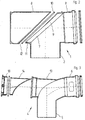
- the device of Figure 1 has an outer pipe bend 1, which is provided with a vertical arm 2 in the form of a spigot end and with a substantially horizontal arm 3 in the form of a socket end.
- the outer pipe bend 1 includes an inner pipe bend 4, which is also provided with a vertical arm 5 in the form of a male end and a substantially horizontal arm 6 in the form of a socket end.
- the device serves to connect a vertical, leading to a condensing boiler section of an air-exhaust pipe with a substantially horizontal leading to a chimney pipe section. The latter has a slight slope to return condensate to the boiler.
- the line sections are not shown in FIG.
- the outer pipe bend 1 is provided with an opening 7 in the rearward continuation of its two arms 2 and 3. This lies in a plane which forms an angle of substantially 45 ° with the two axes of the arms 2 and 3.
- the plane in which the opening 7 is perpendicular to the plane which is spanned by the axes of the two arms 2 and 3 extends.
- a cap 8 which is attachable to a web 9, with the interposition of a sealing ring 10 which is received by a groove 11 of the web 9.
- the sealing effect of the sealing ring 10 is of secondary importance, since the cap 8 does not close the exhaust system of the air-exhaust pipe, but their air flow.
- the sealing ring 10 serves to secure the plug connection between the cap 8 and the web 9 under prestress.
- the inner edge 12 is chamfered.
- the cap 8 makes practical a rearward continuation of the arm 3 of the outer pipe bend. 1
- the inner pipe bend 4 has, according to FIG. 3, a connecting piece 13 which forms a rearward continuation of the arm 3.
- the nozzle 13 serves to receive a flow guiding element 14, the formation of which is clearer from FIG.
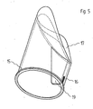
- the flow guide 14 is designed as a rear open hollow body and has a circumferential flange 15, with which it is supported on a complementary shoulder in the interior of the nozzle 13. In the lower area it is provided with a wedge-shaped projection 16 which engages in a complementary, not shown in Figure 3 groove on the inner surface of the nozzle 13. In this way, an insertion of the flow guide 14 in the socket 13 of the inner tube bend 4 only in a defined angular position is possible. This is of crucial importance because the flow guide 14 is provided with a toroidal deflection 17. Their shape is best shown in the perspective view of Figure 5.
- the modified embodiment shown there differs from that of Figure 4 only in that the cylindrical portion is formed longer and that the wedge-shaped projection 16 is not over the entire length of the cylindrical Section extends.
- the flow guide 14 is used in the mounted position to smoothly transfer the exhaust flow from the arm 5 of the inner pipe bend 4 in the arm 6 and thereby avoid the otherwise occurring pressure losses.
- the flow guide 14 In the mounted position, the flow guide 14 is held by a cover 18, the opening of the nozzle 13th the inner pipe bend 4 occlusive.
- the lid 18 can only be screwed into the socket 13 when the flow guide 14 is inserted sufficiently deep into the nozzle, that is, engages with its projection 16 in the complementary groove and accordingly assumes its predetermined angular position.
- the inclined opening 7 of the outer pipe bend 1 allows easy installation of the inner pipe bend 4.
- the latter can be “screwed” through the opening 7 in the outer pipe bend 1 ". Additional space by enlargement of the outer pipe bend 1 is not required.
- the pipe 13 of the inner pipe bend 4 is located inside the cap 8 of the outer pipe bend 1.
- the cap 8 is subtracted from the outer pipe bend 1. Then the annular air ducts are freely visible both in the horizontal and in the vertical line section. Also, the lid 18 of the inner tube bend 4 is optimally accessible. He can be effortlessly unscrewed by hand, whereupon the flow guide 14 can be pulled out of the nozzle 13 without difficulty. Then the adjoining the arm 6 of the inner pipe bend 4 horizontal portion of the exhaust system is directly visible. Only the subsequent to the arm 5 vertical section requires the use of a mirror, which, however, belongs to the standard equipment of the chimney sweep.
- a particularly advantageous feature of the connecting device is that all components, with the exception of the sealing elements, can be made by injection molding of plastic.
Landscapes
- Engineering & Computer Science (AREA)
- Mechanical Engineering (AREA)
- General Engineering & Computer Science (AREA)
- Quick-Acting Or Multi-Walled Pipe Joints (AREA)
- Pipe Accessories (AREA)
- Massaging Devices (AREA)
- Cylinder Crankcases Of Internal Combustion Engines (AREA)
- Magnetic Resonance Imaging Apparatus (AREA)
- Exhaust Silencers (AREA)
Description
- Die Erfindung betrifft eine Einrichtung zum Verbinden zweier im Winkel zueinander verlaufender Abschnitte einer Luft-Abgas-Leitung.
- Luft-Abgas-Leitungen werden für raumluftunabhängige Verbrennungseinrichtungen verwendet, beispielsweise für Heizkessel, und zwar insbesondere für Brennwertgeräte. Dabei verbindet die Luft-Abgas-Leitung die Verbrennungseinrichtung mit dem Kaminkopf. Die innen liegende Abgasführung leitet das Abgas zum Kaminkopf, und die außen liegende Luftführung, die mit der Abgasführung einen Ringraum bildet, versorgt die Verbrennungeinrichtung mit aus der Atmosphäre angesaugter Verbrennungsluft.
- Eine solche Luft-Abgas-Leitung ist zum Beispiel aus der EP 1 089 038 A bekannt.
- Die Luft-Abgas-Leitung muß für regelmäßige Inspektionen zugänglich sein. Dabei muß der Kaminkehrer die Möglichkeit haben, sowohl die Luftführung als auch die Abgasführung zu inspizieren. Die Inspektion findet vorzugsweise an den Umlenkstellen der Luft-Abgas-Leitung statt.
- Der Erfindung liegt die Aufgabe zugrunde, eine bequeme und dennoch zuverlässige Inspektion zu ermöglichen, und zwar auf platzsparende Weise.
- Hierzu ist die Verbindugnseinrichtung nach der Erfindung versehen mit
- einem der Abgasführung zugeordneten inneren Rohrbogen, der in rückwärtiger Fortsetzung eines seiner Arme einen Stutzen aufweist, welcher von einem abnehmbaren Deckel verschlossen ist, und
- einem der Luftführung zugeordneten äußeren Rohrbogen, der den inneren Rohrbogen aufnimmt und in rückwärtiger Fortsetzung seiner beiden Arme eine Öffnung aufweist, die von einer abnehmbaren Kappe verschlossen ist, wobei die Öffnung des äußeren Rohrbogens in einer Ebene liegt, die geneigt zu den Achsen der beiden Arme des äußeren Rohrbogens verläuft.
- Zu Zwecken der Inspektion wird die Kappe des äußeren Rohrbogens abgenommen. Dadurch wird die schräg liegende Öffnung des äußeren Rohrbogens zugänglich. Sie eröffnet den direkten Einblick in beide im Winkel zueinander verlaufende Zweige der Luftführung. Außerdem wird der Deckel, der den Stutzen des inneren Rohrbogens verschließt, zugänglich. Er kann abgenommen werden und ermöglicht den direkten Einblick in denjenigen Zweig der Abgasführung, der die Fortsetzung des Stutzens bildet. In den im Winkel dazu verlaufenden Zweig der Abgasführung ist ohne weitere Hilfsmittel immer noch ein schräger Einblick möglich.
- Von wesentlicher Bedeutung ist, daß das Einfügen des inneren Rohrbogens in den äußeren Rohrbogen'keinerlei Schwierigkeiten bereitet. Die schräg liegende Öffnung des äußeren Rohrbogens bietet die Möglichkeit, den inneren Rohrbogen in den äußeren Rohrbogen "einzudrehen". Der äußere Rohrbogen muß also nicht übermäßig groß dimensioniert sein, um ein Einsetzen des inneren Rohrbogens zu ermöglichen.
- Die beiden Rohrbögen weisen jeweils ein Einsteckende und ein Muffenende auf, die den Einbau der Verbindungseinrichtung in die Luft-Abgas-Leitung ermöglichen. Die Einrichtung wird vorzugsweise an derjenigen Umlenkstelle eingebaut, an der der vom Kessel kommende vertikale Leitungsabschnitt in den zum Kamin führenden horizontalen Leitungsabschnitt umgelenkt wird. Dementsprechend sind die vertikal nach unten gerichteten Arme der Rohrbögen als Einsteckenden ausgebildet. Die anderen Arme, die vorzugsweise in einem Winkel von etwas mehr als 90° abstehen, sind als Muffenenden ausgebildet. Aufgrund des Gefälles kann Kondensat, das sich in der Abgasleitung niedergeschlagen hat, zum Kessel abgeleitet werden.
- Der Stutzen des inneren Rohrbogens liegt praktisch auf der Achse des Muffenendes des inneren Rohrbogens, ist allerdings auch geringfügig geneigt, um den Abfluß von Kondensat zu ermöglichen. Nach Abnahme des Deckels wird der direkte Blick in den horizontalen Zweig der Abgasführung freigegeben.
- Auch die Kappen des äußeren Rohrbogens liegt im wesentlichen auf der Achse des Muffenendes des äußeren Rohrbogens. Nach Abnehmen der Kappe sind die ringförmigen Luftführungen in beiden Richtungen einsehbar.
- Andere Anordnungen und Orientierungen der Verbindungseinrichtung sind ohne weiteres möglich. Beispielsweise kann die Einrichtung am Übergang zum vertikal im Kamin verlaufenden Leitungsabschnitt angeordnet werden. Auch kann der Winkel zwischen den Armen der Rohrbögen wesentlich deutlicher von 90° abweichen, als es für die Erzielung eines Gefälles für das Kondensat erforderlich ist.
- Vorzugsweise verläuft die Ebene, in der die Öffnung des äußeren Rohrbogens liegt, senkrecht zu derjenigen Ebene, die von den Achsen der beiden Arme des äußeren Rohrbogens aufgespannt wird. Dabei ist es besonders vorteilhaft, daß die Ebene, in der die Öffnung des äußeren Rohrbogens liegt, mit den Achsen der beiden Arme des äußeren Rohrbogens gleich Winkel vorzugsweise von im wesentlichen 45° bildet. Die Öffnung liegt also symmetrisch zu beiden Armen des äußeren Rohrbogens.
- Ein weiteres vorteilhaftes Merkmal besteht darin, daß die Kappe, die die Öffnung des äußeren Rohrbogens verschließt, eine rohrförmige, am Ende geschlossene rückwärtige Fortsetzung eines der Arme des äußeren Rohrbogens bildet. Dabei ist es besonders vorteilhaft, daß die Kappe den Stutzen des inneren Rohrbogens aufnimmt. Dies bietet optimale Einbau- und Montagebedingungen.
- Konstruktiv besonders günstig ist es, die Kappe auf einen Steg aufzustecken, der um den Rand der Öffnung des äußeren Rohrbogens herumläuft. Dabei wird zwischen die Kappe und den Steg vorzugsweise ein Dichtring eingelegt, der die Reibkraft zum Halten der Steckverbindung erzeugt. Der Steg weist eine umlaufende Nut auf, in die der Dichtring eingelegt wird. Er gelangt dann durch das Aufstecken der Kappe unter Pressung. Die Dichtfunktion des Ringes ist von sekundärer Bedeutung, da der äußere Rohrbogen und die Kappe Bestandteile der Luftführung sind.
- In wesentlicher Weiterbildung der Erfindung wird vorgeschlagen, daß in den Stutzen des inneren Rohrbogens ein Strömungsleitelement eingesteckt ist, das die Abgasströmung aus dem einen Arm des inneren Rohrbogens in dessen anderen Arm umlenkt. Da der Stutzen des inneren Rohrbogens im Winkel, häufig im wesentlichen senkrecht zur Zuströmrichtung des Abgases liegt, würde die Abgasströmung ohne das Strömungsleitelement praktisch auf ein senkrechtes Hindernis prallen. Dies würde zu erheblichen Turbulenzen und folglich zu einem entsprechenden Druckverlust führen. Trotz der Inspektionsöffnung wirkt also der innere Rohrbogen wie ein glatter Rohrkrümmer. Die durch das Strömungsleitelement bewirkte Verminderung des Druckverlustes entspricht einer zusätzlichen Kaminhöhe bzw. Abgasleitungslänge von zirka drei bis zehn Metern, je nach Anwendungsfall.
- Besonders günstige Strömungsverhältnisse ergeben sich dadurch, daß das Strömungsleitelement eine toroidale Umlenkfläche aufweist.
- Das Strömungsleitelement wird vorzugsweise von dem Deckel, der den Stutzen verschließt, in letzterem gehalten. Dabei kann das Strömungsleitelement einen Bestandteil des Deckels bilden. Dies setzt allerdings voraus, daß der Deckel eine definierte Verschlußposition einnimmt, da anderfalls das Strömungsleitelement seinerseits ein Strömungshindernis bilden würde. Vorteilhafter ist es, das Strömungsleitelement als gesondertes Bauteil auszubilden. Dabei wird vorzugsweise dafür gesorgt, daß die Winkelposition des Strömungsleitelements innerhalb des Stutzens fixiert ist. Hierzu dient insbesondere eine Nase auf der Außenfläche des Strömungsleitelements, die in eine Nut auf der Innenfläche des Stutzens eingreift. Findet der Eingriff nicht statt, so läßt sich das Strömungsleitelement nicht ausreichend tief in den Stutzen einstecken. Es behindert das Aufsetzen, vorzugsweise das Aufschrauben des Deckels und signalisiert dadurch den Montagefehler. Die Nut auf der Innenfläche des Stutzens ist vorzugsweise durchgehend ausgebildet, so daß etwaiges Kondensat abgeführt werden kann.
- Eine Weiterbildung der Erfindung ist dadurch gekennzeichnet, daß das Strömungsleitelement drehbar mit dem Deckel, der den Stutzen des inneren Rohrbogens verschließt, verbunden ist. Das Strömungsleitelement kann also zusammen mit dem Deckel in den Stutzen des inneren Rohrbogens eingeschoben werden, woraufhin der Deckel mit dem Stutzen drehverriegelt wird, beispielsweise über ein Gewinde oder einen Bajonettverschluß. Die Endposition des Deckels hat dabei keinen Einfluß auf die Winkelposition des Strömungselements. Diese Winkelposition bestimmt sich vielmehr über einen formschlüssigen Eingriff des Strömungselements in den Stutzen. Der Vorteil dieser Konstruktion besteht darin, daß der Deckel und das Strömungsleitelement gemeinsam ein- und ausgebaut werden können, wobei dennoch in einfacher Weise eine korrekte Positionierung des Strömungsleitelements gewährleistet ist, und zwar sowohl bezüglich der Winkelposition als auch bezüglich der Einstecktiefe.
- Das Strömungsleitelement kann ohne weiteres als Vollkörper ausgebildet sein. Vorteilhafter, da materialsparender und im Spritzgießverfahren herstellbar, ist eine Ausbildung des Strömungsleitelementes als nach außen offener Hohlkörper. Im Inneren des Hohlkörpers befindet sich vorzugsweise ein Steg, der als Handhabe zum Herausziehen des Strömungsleitelements dient. Ist das Strömungsleitelement als Vollkörper ausgebildet, bringt man eine entsprechende Handhabe auf seiner Außenfläche an.
- Die Erfindung wird im folgenden anhand bevorzugter Auführungsbeispiele im Zusammenhang mit der beiliegenden Zeichnung näher erläutert. Die Zeichnung zeigt in:
- Figur 1 in schematischer Darstellung einen axialen Vertikalschnitt durch eine Einrichtung nach der Erfindung in zusammengebautem Zustand;
- Figur 2 eine äußere Baugruppe der Einrichtung nach Figur 1 in auseinandergezogener Position;
- Figur 3 eine innere Baugruppe der Einrichtung nach Figur 1 in auseinandergezogener Position;
- Figur 4 ein Einzelteil der Baugruppe nach Figur 3 in vergrößertem Maßstab;
- Figur 5 eine abgewandelte Ausführungsform des Einzelteils nach Figur 4.
- Die Einrichtung nach Figur 1 weist einen äußeren Rohrbogen 1 auf, der mit einem vertikalen Arm 2 in Form eines Einsteckendes und mit einem im wesentlichen horizontalen Arm 3 in Form eines Muffenendes versehen ist. Der äußere Rohrbogen 1 enthält einen inneren Rohrbogen 4, der ebenfalls mit einem vertikalen Arm 5 in Form eines Einsteckendes und einem im wesentlichen horizontalen Arm 6 in Form eines Muffenendes versehen ist. Die Einrichtung dient dazu, einen vertikalen, zu einem Brennwert-Heizkessel führenden Abschnitt einer Luft-Abgas-Leitung mit einem im wesentlichen horizontalen, zu einem Kamin führenden Leitungsabschnitt zu verbinden. Letzterer weist ein geringes Gefälle auf, um Kondensat zum Kessel zurückzuführen. Die Leitungsabschnitte sind in Figur 1 nicht dargestellt.
- Wie aus Figur 2 ersichtlich, ist der äußere Rohrbogen 1 in rückwärtiger Fortsetzung seiner beiden Arme 2 und 3 mit einer Öffnung 7 versehen. Diese liegt in einer Ebene, die mit den beiden Achsen der Arme 2 und 3 einen Winkel von im wesentlichen 45° bildet. Außerdem verläuft die Ebene, in der die Öffnung 7 liegt, senkrecht zu derjenigen Ebene, die von den Achsen der beiden Arme 2 und 3 aufgespannt wird.
- Zum Verschließen der Öffnung 7 dient eine Kappe 8, die auf einen Steg 9 aufsteckbar ist, und zwar unter Zwischenschaltung eines Dichtrings 10, der von einer Nut 11 des Steges 9 aufgenommen wird. Die Dichtwirkung des Dichtrings 10 ist von sekundärer Bedeutung, da die Kappe 8 nicht die Abgasführung der Luft-Abgas-Leitung verschließt, sondern deren Luftführung. Hingegen dient der Dichtring 10 dazu, die Steckverbindung zwischen der Kappe 8 und dem Steg 9 unter Vorspannung zu sichern. Um das Aufstecken der Kappe 8 zu vereinfachen, ist deren Innenrand 12 abgeschrägt. Die Kappe 8 bildet praktische eine rückwärtige Fortsetzung des Arms 3 des äußeren Rohrbogens 1.
- Der innere Rohrbogen 4 weist gemäß Figur 3 einen Stutzen 13 auf, der eine rückwärtige Fortsetzung des Arms 3 bildet. Der Stutzen 13 dient zur Aufnahme eines Strömungsleitelements 14, dessen Ausbildung deutlicher aus Figur 4 hervorgeht. Das Strömungsleitelement 14 ist als rückwärtig offener Hohlkörper ausgebildet und weist einen umlaufenden Flansch 15 auf, mit dem er sich an einer komplementären Schulter im Inneren des Stutzens 13 abstützt. Im unteren Bereich ist er mit einem keilförmigen Vorsprung 16 versehen, der in eine komplementäre, in Figur 3 nicht dargestellt Nut auf der Innenfläche des Stutzens 13 eingreift. Auf diese Weise ist ein Einstecken des Strömungsleitelements 14 in den Stutzen 13 des inneren Rohrbogens 4 nur in definierter Winkelposition möglich. Dies ist deshalb von ausschlaggebender Bedeutung, weil das Strömungsleitelement 14 mit einer toroidalen Umlenkfläche 17 versehen ist. Deren Gestalt ergibt sich am besten aus der perspektivischen Darstellung nach Figur 5. Die dort gezeigte abgewandelte Ausführungsform unterscheidet sich von der nach Figur 4 lediglich dadurch, daß der zylindrische Abschnitt länger ausgebildet ist und daß der keilförmige Vorsprung 16 sich nicht über die gesamte Länge des zylindrischen Abschnitts erstreckt.
- Das Strömungsleitelement 14 dient in montierter Lage dazu, die Abgaströmung sanft aus dem Arm 5 des inneren Rohrbogens 4 in dessen Arm 6 überzuleiten und dadurch die sonst auftretenden Druckverluste zu vermeiden.
- In montierter Lage wird das Strömungsleitelement 14 von einem Deckel 18 gehalten, der die Öffnung des Stutzens 13 des inneren Rohrbogens 4 verschließ. Der Deckel 18 kann in den Stutzen 13 nur dann eingeschraubt werden, wenn das Strömungsleitelement 14 ausreichend tief in den Stutzen eingesteckt ist, das heißt, mit seinem Vorsprung 16 in die komplementäre Nut eingreift und dementsprechend seine vorgegebene Winkelposition einnimmt.
- Zum Herausziehen des Strömungsleitelements 15 dient ein im Inneren ausgebildeter Ansatz 19, der mit zwei Fingern ergriffen werden kann.
- Die geneigte Öffnung 7 des äußeren Rohrbogens 1 ermöglicht einen problemlosen Einbau des inneren Rohrbogens 4. Letzterer kann durch die Öffnung 7 hindurch in den äußeren Rohrbogen 1 "eingedreht" werden. Zusätzlicher Platz durch Vergrößerung des äußeren Rohrbogens 1 ist nicht erforderlich. In montierter Lage befindet sich der Stutzen 13 des inneren Rohrbogens 4 innerhalb der Kappe 8 des äußeren Rohrbogens 1.
- Soll die Luft-Abgas-Leitung inspiziert werden, so wird die Kappe 8 vom äußeren Rohrbogen 1 abgezogen. Sodann sind sowohl im horizontalen als auch im vertikalen Leitungsabschnitt die ringförmigen Luftführungen frei einsehbar. Auch ist der Deckel 18 des inneren Rohrbogens 4 optimal zugänglich. Er kann mühelos mit der Hand abgeschraubt werden, woraufhin sich das Strömungsleitelement 14 ohne Schwierigkeiten aus dem Stutzen 13 herausziehen läßt. Sodann ist der an den Arm 6 des inneren Rohrbogens 4 anschließende horizontale Abschnitt der Abgasführung direkt einsehbar. Lediglich der an den Arm 5 anschließende vertikale Abschnitt bedarf des Einsatzes eines Spiegels, der allerdings zur Standardausrüstung des Kaminkehrers gehört.
- Ein besonders vorteilhaftes Merkmal der Verbindungseinrichtung besteht darin, daß sämtliche Bauteile, mit Ausnahme der Dichtelemente, im Spritzgießverfahren aus Kunststoff hergestellt werden können.
- Im Rahmen der Erfindung sind durchaus Abwandlungsmöglichkeiten gegeben. So kann die Orientierung der schrägen Öffnung des äußeren Rohrbogens anders gewählt werden, wobei allerdings die dargestellte Ausrichtung derzeit als optimal angesehen wird. Ferner können die Einsteck- und Kupplungsenden der Rohrbögen miteinander vertauscht werden, beispielsweise auch nur für einen der beiden Rohrbögen. Eine weitere Abwandlunsmöglichkeit bietet der innere Rohrbogen. Er kann als T-Stück gestaltet sein, wobei der Arm 6 direkt in den Stutzen 13 übergeht. Dabei entfällt allerdings die Möglichkeit, den Stutzen 13 mit Gefälle zum Ableiten von Kondensat zu versehen. Der Winkel zwischen den Armen der Rohrbögen kann durchaus stark von 90° abweichen.
Claims (10)
- Einrichtung zum Verbinden zweier im Winkel zueinander verlaufender Abschnitte einer Luft-Abgas-Leitung, mit- einem der Abgasführung zugeordneten inneren Rohrbogen (4), der in rückwärtiger Fortsetzung eines (6) seiner Arme (5,6) einen Stutzen (13) aufweist, welcher von einem abnehmbaren Deckel (18) verschlossen ist, und- einem der Luftführung zugeordneten äußeren Rohrbogen (1), der den inneren Rohrbogen (4) aufnimmt und in rückwärtiger Fortsetzung seiner beiden Arme (2,3) eine Öffnung (7) aufweist, die von einer abnehmbaren Kappe (8) verschlossen ist, wobei die Öffnung (7) des äußeren Rohrbogens (1) in einer Ebene liegt, die geneigt zu den Achsen der beiden Arme (2,3) des äußeren Rohrbogens (1) verläuft.
- Einrichtung nach Anspruch 1, dadurch gekennzeichnet, daß die Ebene, in der die Öffnung (7) des äußeren Rohrbogens (1) liegt, senkrecht zu derjenigen Ebene verläuft, die von den Achsen der beiden Arme (2,3) des äußeren Rohrbogens (1) aufgespannt wird.
- Einrichtung nach Anspruch 1 oder 2, dadurch gekennzeichnet, daß die Ebene, in der die Öffnung (7) des äußeren Rohrbogens (1) liegt, mit den Achsen der beiden Arme (2,3) des äußeren Rohrbogens (1) gleiche Winkel vorzugsweise von im wesentlichen 45° bildet.
- Einrichtung nach einem der Ansprüche 1 bis 3, dadurch gekennzeichnet, daß die Kappe (8), die die Öffnung des äußeren Rohrbogens (1) verschließt, eine rohrförmige, am Ende geschlossene rückwärtige Fortsetzung eines (3) der Arme (2,3) des äußeren Rohrbogens (1) bildet.
- Einrichtung nach einem der Ansprüche 1 bis 4, dadurch gekennzeichnet, daß die Kappe (8) den Stutzen (13) des inneren Rohrbogens (4) aufnimmt, wobei der Stutzen (13) des inneren Rohrbogens (4) vorzugsweise ein Gefälle zum Ableiten von Kondensat aufweist.
- Einreichung nach einem der Ansprüche 1 bis 5, dadurch gekennzeichnet, daß in den Stutzen (13) des inneren Rohrbogens (4) ein Strömungsleitelement (14) eingesteckt ist, das die Abgasströmung aus dem einen Arm (5) des inneren Rohrbogens (4) in dessen anderen Arm (6) umlenkt.
- Einrichtung nach Anspruch 6, dadurch gekennzeichnet, daß das Strömungsleitelement (14) eine toroidale Umlenkfläche (17) aufweist.
- Einrichtung nach Anspruch 6 oder 7, dadurch gekennzeichnet, daß das Strömungsleitelement (14) von dem Deckel (18), der den Stutzen (13) verschließt, in letzterem gehalten wird.
- Einrichtung nach einem der Ansprüche 6 bis 8, dadurch gekennzeichnet, daß die Winkelposition des Strömungsleitelements (14) innerhalb des Stutzens (13) fixiert ist.
- Einrichtung nach einem der Ansprüche 6 bis 9, dadurch gekennzeichnet, daß das Strömungsleitelement (14) drehbar mit dem Deckel (18), der den Stutzen (13) des inneren Rohrbogens (4) verschließt, verbunden ist.
Applications Claiming Priority (2)
| Application Number | Priority Date | Filing Date | Title |
|---|---|---|---|
| DE10159564 | 2001-12-05 | ||
| DE10159564A DE10159564C1 (de) | 2001-12-05 | 2001-12-05 | Einrichtung zum Verbinden zweier Abschnitte einer Luft-Abgas-Leitung |
Publications (3)
| Publication Number | Publication Date |
|---|---|
| EP1318352A2 EP1318352A2 (de) | 2003-06-11 |
| EP1318352A3 EP1318352A3 (de) | 2003-12-10 |
| EP1318352B1 true EP1318352B1 (de) | 2006-08-02 |
Family
ID=7708023
Family Applications (1)
| Application Number | Title | Priority Date | Filing Date |
|---|---|---|---|
| EP02026202A Expired - Lifetime EP1318352B1 (de) | 2001-12-05 | 2002-11-26 | Einrichtung zum Verbinden zweier Abschnitte einer Luft-Abgas-Leitung |
Country Status (3)
| Country | Link |
|---|---|
| EP (1) | EP1318352B1 (de) |
| AT (1) | ATE335168T1 (de) |
| DE (2) | DE10159564C1 (de) |
Families Citing this family (5)
| Publication number | Priority date | Publication date | Assignee | Title |
|---|---|---|---|---|
| DE102012106707B3 (de) * | 2012-07-24 | 2013-11-07 | Dieter Bächle | Abgas-/Verbrennungsluft-Rohrsystem |
| DE202016101125U1 (de) * | 2016-03-02 | 2017-06-06 | Dieter Bächle | Rohreinheit zur Luftversorgung sowie Abführung von Abgasen von Verbrennungseinrichtungen |
| EP3406972A1 (de) * | 2017-05-24 | 2018-11-28 | Vaillant GmbH | Koaxiales abgasrohr mit messöffnung |
| DE102019119859B4 (de) * | 2019-07-23 | 2021-02-11 | Welipa Ag | Montagemodul zur Anordnung einer Schachteinführung, Schachteinführungseinheit sowie Verfahren |
| CN112594757A (zh) * | 2021-01-08 | 2021-04-02 | 深圳市新厨帮科技有限公司 | 一种节能型整体厨房组件 |
Family Cites Families (7)
| Publication number | Priority date | Publication date | Assignee | Title |
|---|---|---|---|---|
| DE1681792U (de) * | 1954-06-11 | 1954-08-19 | Else Bechmann | Ofenrohr fuer waschoefen. |
| US5012793A (en) * | 1989-10-05 | 1991-05-07 | The Field Controls Company | Power vented direct vent system |
| DE9113570U1 (de) * | 1991-10-31 | 1992-01-02 | Ruka Metallverarbeitung Gmbh & Co., 7067 Pluederhausen | Rohrbogen |
| DE4303954C2 (de) * | 1993-02-10 | 1994-11-24 | Burgmann Dichtungswerk Feodor | Anordnung zur Befestigung eines Ansatzstutzens an einer Anschlußöffnung in einem Rohrabschnitt eines keramischen Innenrohrs eines Schornsteins |
| DE4331194C1 (de) * | 1993-09-14 | 1994-10-06 | Braas Gmbh | Doppelwandiges Rohrleitungssystem |
| NL1013167C2 (nl) * | 1999-09-29 | 2001-03-30 | Ubbink Nederland Bv | Uitmondingsconstructie voor gevel-gastoestellen. |
| DE20022107U1 (de) * | 2000-12-30 | 2001-03-01 | REHAU AG + Co., 95111 Rehau | Vorrichtung für den Einsatz in Abgasanlagen |
-
2001
- 2001-12-05 DE DE10159564A patent/DE10159564C1/de not_active Expired - Fee Related
-
2002
- 2002-11-26 DE DE50207706T patent/DE50207706D1/de not_active Expired - Lifetime
- 2002-11-26 EP EP02026202A patent/EP1318352B1/de not_active Expired - Lifetime
- 2002-11-26 AT AT02026202T patent/ATE335168T1/de active
Also Published As
| Publication number | Publication date |
|---|---|
| ATE335168T1 (de) | 2006-08-15 |
| DE10159564C1 (de) | 2003-06-26 |
| DE50207706D1 (de) | 2006-09-14 |
| EP1318352A2 (de) | 2003-06-11 |
| EP1318352A3 (de) | 2003-12-10 |
Similar Documents
| Publication | Publication Date | Title |
|---|---|---|
| DE4020171C1 (de) | ||
| DE10203521A1 (de) | Schnellverschlusskupplung | |
| DE102007006588A1 (de) | Schnellverschlusskupplung | |
| DE4029792A1 (de) | Anordnung zur befestigung einer handbrause | |
| DE19519073B4 (de) | Vorrichtung zur Verbindung von Rohrleitungsabschnitten untereinander | |
| DE4308367A1 (de) | Verbindungsvorrichtung | |
| DE102016223355A1 (de) | Verbindungsvorrichtung | |
| DE10159564C1 (de) | Einrichtung zum Verbinden zweier Abschnitte einer Luft-Abgas-Leitung | |
| DE102012005930A1 (de) | Steckverbindungsanordnung | |
| EP3327884B1 (de) | Rohreinführung | |
| DE19621613A1 (de) | Bausatz zum Erstellen einer Abgasleitung | |
| DE3322797C1 (de) | Schlauchanschluß | |
| EP0170042B1 (de) | Kupplung | |
| EP1717380B1 (de) | Anschlussvorrichtung zum Anschliessen eines Sanitärartikels | |
| DE10159558C1 (de) | Einrichtung zum Verbinden von Rohrleitungsabschnitten | |
| DE3346614C2 (de) | ||
| DE19717333B4 (de) | Mehrteiliges Gehäuse für eine Heizungs- und/oder Klimaanlage eines Kraftfahrzeugs | |
| DE102008051269A1 (de) | Entleerungseinrichtung | |
| EP0931685A1 (de) | Verriegelungsvorrichtung für eine einem Tankeinfüllstutzen zugeordnete Verschlussklappe | |
| EP0074034A2 (de) | Einbauhilfe für ein Einsatzteil in einen Abwasser-Sammel-behälter | |
| WO2021009093A1 (de) | Ablaufstutzen zum getrennten auslassen von flüssigkeiten unterschiedlicher dichte | |
| EP0677722A2 (de) | Rohrleitungs-Pass-Stück, insbesondere für opto-elektronische Volumenstrom-Messungen in Rohrleitungen | |
| EP3214353A1 (de) | Rohreinheit zur luftversorgung sowie abführung von abgasen von verbrennungseinrichtungen | |
| EP0146156A2 (de) | Kunststoffkabelumhüllung | |
| DE19907051A1 (de) | Reinigungsgerät |
Legal Events
| Date | Code | Title | Description |
|---|---|---|---|
| PUAI | Public reference made under article 153(3) epc to a published international application that has entered the european phase |
Free format text: ORIGINAL CODE: 0009012 |
|
| AK | Designated contracting states |
Designated state(s): AT BE BG CH CY CZ DE DK EE ES FI FR GB GR IE IT LI LU MC NL PT SE SK TR |
|
| AX | Request for extension of the european patent |
Extension state: AL LT LV MK RO SI |
|
| PUAL | Search report despatched |
Free format text: ORIGINAL CODE: 0009013 |
|
| AK | Designated contracting states |
Kind code of ref document: A3 Designated state(s): AT BE BG CH CY CZ DE DK EE ES FI FR GB GR IE IT LI LU MC NL PT SE SK TR |
|
| AX | Request for extension of the european patent |
Extension state: AL LT LV MK RO SI |
|
| 17P | Request for examination filed |
Effective date: 20040108 |
|
| AKX | Designation fees paid |
Designated state(s): AT BE BG CH CY CZ DE DK EE ES FI FR GB GR IE IT LI LU MC NL PT SE SK TR |
|
| GRAP | Despatch of communication of intention to grant a patent |
Free format text: ORIGINAL CODE: EPIDOSNIGR1 |
|
| GRAS | Grant fee paid |
Free format text: ORIGINAL CODE: EPIDOSNIGR3 |
|
| GRAA | (expected) grant |
Free format text: ORIGINAL CODE: 0009210 |
|
| AK | Designated contracting states |
Kind code of ref document: B1 Designated state(s): AT BE BG CH CY CZ DE DK EE ES FI FR GB GR IE IT LI LU MC NL PT SE SK TR |
|
| PG25 | Lapsed in a contracting state [announced via postgrant information from national office to epo] |
Ref country code: IT Free format text: LAPSE BECAUSE OF FAILURE TO SUBMIT A TRANSLATION OF THE DESCRIPTION OR TO PAY THE FEE WITHIN THE PRESCRIBED TIME-LIMIT;WARNING: LAPSES OF ITALIAN PATENTS WITH EFFECTIVE DATE BEFORE 2007 MAY HAVE OCCURRED AT ANY TIME BEFORE 2007. THE CORRECT EFFECTIVE DATE MAY BE DIFFERENT FROM THE ONE RECORDED. Effective date: 20060802 Ref country code: FI Free format text: LAPSE BECAUSE OF FAILURE TO SUBMIT A TRANSLATION OF THE DESCRIPTION OR TO PAY THE FEE WITHIN THE PRESCRIBED TIME-LIMIT Effective date: 20060802 Ref country code: CZ Free format text: LAPSE BECAUSE OF FAILURE TO SUBMIT A TRANSLATION OF THE DESCRIPTION OR TO PAY THE FEE WITHIN THE PRESCRIBED TIME-LIMIT Effective date: 20060802 Ref country code: SK Free format text: LAPSE BECAUSE OF FAILURE TO SUBMIT A TRANSLATION OF THE DESCRIPTION OR TO PAY THE FEE WITHIN THE PRESCRIBED TIME-LIMIT Effective date: 20060802 Ref country code: IE Free format text: LAPSE BECAUSE OF FAILURE TO SUBMIT A TRANSLATION OF THE DESCRIPTION OR TO PAY THE FEE WITHIN THE PRESCRIBED TIME-LIMIT Effective date: 20060802 |
|
| REG | Reference to a national code |
Ref country code: GB Ref legal event code: FG4D Free format text: NOT ENGLISH |
|
| RAP2 | Party data changed (patent owner data changed or rights of a patent transferred) |
Owner name: CENTROTHERM SYSTEMTECHNIK GMBH |
|
| REG | Reference to a national code |
Ref country code: CH Ref legal event code: EP |
|
| REG | Reference to a national code |
Ref country code: IE Ref legal event code: FG4D Free format text: LANGUAGE OF EP DOCUMENT: GERMAN |
|
| REF | Corresponds to: |
Ref document number: 50207706 Country of ref document: DE Date of ref document: 20060914 Kind code of ref document: P |
|
| NLT2 | Nl: modifications (of names), taken from the european patent patent bulletin |
Owner name: CENTROTHERM SYSTEMTECHNIK GMBH Effective date: 20060823 |
|
| PG25 | Lapsed in a contracting state [announced via postgrant information from national office to epo] |
Ref country code: DK Free format text: LAPSE BECAUSE OF FAILURE TO SUBMIT A TRANSLATION OF THE DESCRIPTION OR TO PAY THE FEE WITHIN THE PRESCRIBED TIME-LIMIT Effective date: 20061102 Ref country code: BG Free format text: LAPSE BECAUSE OF FAILURE TO SUBMIT A TRANSLATION OF THE DESCRIPTION OR TO PAY THE FEE WITHIN THE PRESCRIBED TIME-LIMIT Effective date: 20061102 Ref country code: SE Free format text: LAPSE BECAUSE OF FAILURE TO SUBMIT A TRANSLATION OF THE DESCRIPTION OR TO PAY THE FEE WITHIN THE PRESCRIBED TIME-LIMIT Effective date: 20061102 |
|
| PG25 | Lapsed in a contracting state [announced via postgrant information from national office to epo] |
Ref country code: ES Free format text: LAPSE BECAUSE OF FAILURE TO SUBMIT A TRANSLATION OF THE DESCRIPTION OR TO PAY THE FEE WITHIN THE PRESCRIBED TIME-LIMIT Effective date: 20061113 |
|
| GBT | Gb: translation of ep patent filed (gb section 77(6)(a)/1977) |
Effective date: 20061023 |
|
| PG25 | Lapsed in a contracting state [announced via postgrant information from national office to epo] |
Ref country code: MC Free format text: LAPSE BECAUSE OF NON-PAYMENT OF DUE FEES Effective date: 20061130 |
|
| PG25 | Lapsed in a contracting state [announced via postgrant information from national office to epo] |
Ref country code: PT Free format text: LAPSE BECAUSE OF FAILURE TO SUBMIT A TRANSLATION OF THE DESCRIPTION OR TO PAY THE FEE WITHIN THE PRESCRIBED TIME-LIMIT Effective date: 20070102 |
|
| ET | Fr: translation filed | ||
| REG | Reference to a national code |
Ref country code: IE Ref legal event code: FD4D |
|
| PLBE | No opposition filed within time limit |
Free format text: ORIGINAL CODE: 0009261 |
|
| STAA | Information on the status of an ep patent application or granted ep patent |
Free format text: STATUS: NO OPPOSITION FILED WITHIN TIME LIMIT |
|
| 26N | No opposition filed |
Effective date: 20070503 |
|
| PG25 | Lapsed in a contracting state [announced via postgrant information from national office to epo] |
Ref country code: GR Free format text: LAPSE BECAUSE OF FAILURE TO SUBMIT A TRANSLATION OF THE DESCRIPTION OR TO PAY THE FEE WITHIN THE PRESCRIBED TIME-LIMIT Effective date: 20061103 |
|
| PG25 | Lapsed in a contracting state [announced via postgrant information from national office to epo] |
Ref country code: EE Free format text: LAPSE BECAUSE OF FAILURE TO SUBMIT A TRANSLATION OF THE DESCRIPTION OR TO PAY THE FEE WITHIN THE PRESCRIBED TIME-LIMIT Effective date: 20060802 |
|
| PG25 | Lapsed in a contracting state [announced via postgrant information from national office to epo] |
Ref country code: TR Free format text: LAPSE BECAUSE OF FAILURE TO SUBMIT A TRANSLATION OF THE DESCRIPTION OR TO PAY THE FEE WITHIN THE PRESCRIBED TIME-LIMIT Effective date: 20060802 |
|
| PG25 | Lapsed in a contracting state [announced via postgrant information from national office to epo] |
Ref country code: CY Free format text: LAPSE BECAUSE OF FAILURE TO SUBMIT A TRANSLATION OF THE DESCRIPTION OR TO PAY THE FEE WITHIN THE PRESCRIBED TIME-LIMIT Effective date: 20060802 |
|
| REG | Reference to a national code |
Ref country code: FR Ref legal event code: PLFP Year of fee payment: 14 |
|
| PGFP | Annual fee paid to national office [announced via postgrant information from national office to epo] |
Ref country code: GB Payment date: 20151118 Year of fee payment: 14 Ref country code: DE Payment date: 20151130 Year of fee payment: 14 Ref country code: CH Payment date: 20151118 Year of fee payment: 14 Ref country code: IT Payment date: 20151125 Year of fee payment: 14 Ref country code: LU Payment date: 20151119 Year of fee payment: 14 |
|
| PGFP | Annual fee paid to national office [announced via postgrant information from national office to epo] |
Ref country code: AT Payment date: 20151119 Year of fee payment: 14 Ref country code: FR Payment date: 20151119 Year of fee payment: 14 Ref country code: NL Payment date: 20151118 Year of fee payment: 14 Ref country code: BE Payment date: 20151118 Year of fee payment: 14 |
|
| PG25 | Lapsed in a contracting state [announced via postgrant information from national office to epo] |
Ref country code: BE Free format text: LAPSE BECAUSE OF NON-PAYMENT OF DUE FEES Effective date: 20161130 |
|
| REG | Reference to a national code |
Ref country code: DE Ref legal event code: R119 Ref document number: 50207706 Country of ref document: DE |
|
| REG | Reference to a national code |
Ref country code: CH Ref legal event code: PL |
|
| REG | Reference to a national code |
Ref country code: NL Ref legal event code: MM Effective date: 20161201 |
|
| REG | Reference to a national code |
Ref country code: AT Ref legal event code: MM01 Ref document number: 335168 Country of ref document: AT Kind code of ref document: T Effective date: 20161126 |
|
| GBPC | Gb: european patent ceased through non-payment of renewal fee |
Effective date: 20161126 |
|
| PG25 | Lapsed in a contracting state [announced via postgrant information from national office to epo] |
Ref country code: LI Free format text: LAPSE BECAUSE OF NON-PAYMENT OF DUE FEES Effective date: 20161130 Ref country code: CH Free format text: LAPSE BECAUSE OF NON-PAYMENT OF DUE FEES Effective date: 20161130 |
|
| REG | Reference to a national code |
Ref country code: FR Ref legal event code: ST Effective date: 20170731 |
|
| PG25 | Lapsed in a contracting state [announced via postgrant information from national office to epo] |
Ref country code: AT Free format text: LAPSE BECAUSE OF NON-PAYMENT OF DUE FEES Effective date: 20161126 |
|
| PG25 | Lapsed in a contracting state [announced via postgrant information from national office to epo] |
Ref country code: NL Free format text: LAPSE BECAUSE OF NON-PAYMENT OF DUE FEES Effective date: 20161201 Ref country code: LU Free format text: LAPSE BECAUSE OF NON-PAYMENT OF DUE FEES Effective date: 20161130 |
|
| PG25 | Lapsed in a contracting state [announced via postgrant information from national office to epo] |
Ref country code: IT Free format text: LAPSE BECAUSE OF NON-PAYMENT OF DUE FEES Effective date: 20161126 Ref country code: FR Free format text: LAPSE BECAUSE OF NON-PAYMENT OF DUE FEES Effective date: 20161130 |
|
| PG25 | Lapsed in a contracting state [announced via postgrant information from national office to epo] |
Ref country code: GB Free format text: LAPSE BECAUSE OF NON-PAYMENT OF DUE FEES Effective date: 20161126 Ref country code: DE Free format text: LAPSE BECAUSE OF NON-PAYMENT OF DUE FEES Effective date: 20170601 |
|
| REG | Reference to a national code |
Ref country code: BE Ref legal event code: MM Effective date: 20161130 |