EP1318088A1 - Spannvorrichtung und Umsetzvorrichtung mit einer derartigen Spannvorrichtung - Google Patents
Spannvorrichtung und Umsetzvorrichtung mit einer derartigen Spannvorrichtung Download PDFInfo
- Publication number
- EP1318088A1 EP1318088A1 EP02027201A EP02027201A EP1318088A1 EP 1318088 A1 EP1318088 A1 EP 1318088A1 EP 02027201 A EP02027201 A EP 02027201A EP 02027201 A EP02027201 A EP 02027201A EP 1318088 A1 EP1318088 A1 EP 1318088A1
- Authority
- EP
- European Patent Office
- Prior art keywords
- belt
- axis
- clamping device
- belts
- carrier
- Prior art date
- Legal status (The legal status is an assumption and is not a legal conclusion. Google has not performed a legal analysis and makes no representation as to the accuracy of the status listed.)
- Granted
Links
Images


Classifications
-
- B—PERFORMING OPERATIONS; TRANSPORTING
- B65—CONVEYING; PACKING; STORING; HANDLING THIN OR FILAMENTARY MATERIAL
- B65G—TRANSPORT OR STORAGE DEVICES, e.g. CONVEYORS FOR LOADING OR TIPPING, SHOP CONVEYOR SYSTEMS OR PNEUMATIC TUBE CONVEYORS
- B65G47/00—Article or material-handling devices associated with conveyors; Methods employing such devices
- B65G47/52—Devices for transferring articles or materials between conveyors i.e. discharging or feeding devices
Definitions
- the invention relates to a device for clamping at least two in Belt length invariant, with a first belt around one is guided around the first axis, which repeats an actuating movement in one essentially orthogonal to the axis direction of the first axis running adjusting direction, and wherein the first belt and a second belts are guided around a common second axis, the biasing directions of the first belt and the second Belt in the area of the second axis one of 0 ° and 180 ° enclose different angles with each other.
- first and second belts will be under the tension direction understood the direction of action of the respective pretensioning force Apply belt on the second axle.
- a generic tensioning device is found, for example, in the Bosch GmbH sold under the name HQ2 / S lifting cross unit Use.
- Such lifting cross units serve in one Conveyor system for workpieces or workpiece carriers, which on a first conveyor line transported workpieces or workpiece carriers to stop, to withdraw from the funds of the first conveyor line and to a second one that is usually orthogonal to the first conveyor line Transfer conveyor line.
- the lifting cross unit comprises a lifting unit with integrated lifting device, for example a pneumatic cylinder, and one or more guide rods.
- an actuator of Power device such as the piston rod of the pneumatic cylinder, and a guide plate is firmly connected to the guide rods, on the one Multiple axes for the storage of idler pulleys are provided.
- the common axis of the HQ2 / S lifting cross unit also makes Adjusting belt and drive belt with the lifting movement, so that in Do not follow the tension of the adjusting straps as a result of this lifting movement changes, but the tension of the drive belt. It is therefore one Tensioning device provided in the form of tensioning rollers, which at the Assembly of the entire device can be adjusted. The change in length the belt is not balanced, i.e. the tension is depending Different stroke positions. When using an additional, springy stored tensioning roller, the belt tension can be essentially constant being held.
- lifting cross unit HQ1 / O there is a further lifting cross unit from Bosch GmbH referenced, namely the lifting cross unit HQ1 / O.
- the Drive belt formed by a round cord of polyurethane, so that it on the lifting movement as well as on manufacturing and assembly tolerances an elastic stretch, i.e. can react by changing the length.
- a tensioning device solved type in which the second axis a Spring unit is assigned, which they in the sense of tensioning the first Belt and the second belt pretensioned and which one Adjustment movement of the first axis a compensating movement of the second Axis from the by the axis direction of the second axis with the Preload directions of the first belt and the second belt, respectively before the start of the actuating movement.
- the compensating movement according to the invention can both the distance of the first axis from the second axis as well as the distance of the second Axis from the drive axis of the second belt essentially be kept constant. This takes into account the length invariance the belt so that the pretension of the belt in the Can be kept essentially constant.
- the change in the preload of the Spring unit can, for example, by using a preloaded Coil spring, be it a helical compression spring or a coil tension spring, or a gas spring with reference to the total diameter of the piston comparatively thin piston rod kept to a minimum become.
- Another advantage of the invention is the simplification of the structure of the Clamping device and thus to see the entire transfer device, which can be achieved by using the invention an additional tension pulley can be dispensed with.
- the first axis (or the plurality of first axes) on one relative to a base unit adjustable frame is mounted, and that the second axis (or the Plurality of second axes) is mounted on a carrier which on the Frame is guided relative to this, whereby the Spring unit at one end on the frame and at the other end on the carrier supported.
- This enables a particularly compact and therefore space-saving construction not only the clamping device, but the entire transfer device.
- the carrier on the drive axle of the second belt or the housing of the drive motor for the second belt or alternatively on the Base unit feasible to store.
- a base plate that can be attached or attached to the frame the clamping device and / or the carrier made of sheet metal, preferably Sheet metal, is made.
- the base plate and / or the Carrier as punched or cut (for example by means of a Lasers) and bent sheet metal part if desired.
- At least one bearing of the second axis as one-sided open recess is formed. This can be done in normal operation
- the second axle falls out of this bearing due to the preload of the first belt and / or by pretensioning the second belt can be prevented, and in a simple manner by appropriate Orientation of the open side of the recess.
- an associated guide recess may be provided.
- a guide bar can be made by bending a sheet metal web.
- the guide bar is essentially orthogonal to Preload direction of the second belt before the actuation movement begins runs, and that the guide recess in terms of dimensions the guide bar that penetrates them with such a large excess is that the beam is substantially parallel to the second axis extending axis is pivotable.
- the straps can preferably be one to achieve length invariance Have insert made of tensile material, for example an insert made of tensile glass fiber material, tensile plastic fibers or metal, especially steel wires. But not just this length invariant Training, but also the training of the belt as a timing belt can in addition to the durability of the straps, the precision of the movement of the improve the first belt.
- the tensioning device as a whole, but also the base plate or / and the carrier as individual parts of the tensioning device is proposed that on the base plate and / or the carrier a holding mandrel for Holding the coil spring is provided and / or that on the base plate or / and the carrier at least one stop to limit the Relative movement between the base plate and carrier is provided.
- the invention further relates to one Device for moving workpieces or workpiece carriers with a tensioning device according to the invention.
- a transfer device according to the invention is generally designated 10. Such transfer devices are known in the prior art and are therefore not to be described in detail here.
- the transfer device 10 is used to transfer workpieces or workpiece carriers from a first conveyor section T 1 to a second conveyor section T 2 .
- the conveyor belts of the first conveyor section T 1 are dash-dotted in FIG. 1 and those of the second conveyor section T 2 are dash-dotted lines.
- the transfer device 10 comprises a lifting plate 12 which can be displaced, in particular raised and lowered, in the adjusting direction S by means of a lifting device 14, for example a pneumatic cylinder. In this way, the workpieces or workpiece carriers can be brought out of engagement with the conveyor belts of the first conveyor section T 1 .
- Deflection rollers 16 are mounted on the lifting plate 12 so as to be rotatable about axes A 1 and A 2 , the axial directions of these axes A 1 and A 2 running essentially parallel to the running direction of the conveyor belts of the first conveyor section T 1 .
- Adjustment belts 18 are guided around these deflection rollers 16, which are driven after the lifting of the workpieces or workpiece carriers from the first conveyor path T 1 in order to move the workpiece or the workpiece carriers transversely to the running direction of the conveyor belts of the first conveyor path T 1 and thus with the To bring treadmills of the second conveyor line T 2 into engagement.
- the axes A 1 and A 2 together form a first axis A in the sense of the present invention.
- a drive belt 24 is guided around the pinion 20, which is rotatably mounted on an axis B or with a rotatable shaft B are non-rotatably connected.
- a Another pinion 22 is arranged around which a drive belt 24 is guided is.
- the drive belt 24 can by means of a not shown in Fig. 1 Drive unit, for example a geared motor, can be driven.
- the gear motor can in turn be activated or controlled by a control unit. be deactivated by suitable sensors of the position of the workpieces or workpiece carrier receives corresponding sensor signals, and these are processed according to a predetermined algorithm.
- the adjusting straps 18 and the drive belt 24 preferably as a toothed belt with glass fiber insert are trained. On the one hand, this allows the desired Precision of the control of the movement of the adjusting belt 18 ensured become. On the other hand, such are essentially distinguished length-invariant straps with a high durability.
- the lifting device 14 has a base plate 26 with a higher-level assembly (not shown in FIG. 1) connected is. Furthermore, the control element 28 can be seen in FIG. 1 a power device of the lifting device 14 and two guide rods 30, which are used to guide the lifting plate 12 in the setting direction S.
- the axis B common to the belts 18 and 24 is in a tensioning device 32 stored, their structure and function detailed below to be explained:
- the clamping device 32 comprises a base plate 34, which over the Guide rods 30 is connected to the lifting plate 12.
- the base plate 34 is a punched or cut (for example by means of a Lasers) and bent sheet metal part. In particular, it includes three tabs from the sheet metal plane according to that shown in Fig. 1 Orientation are bent down, namely two guide rails 36 and a retaining web 38 for a helical compression spring 40.
- the clamping device 32 comprises a carrier 42, in which the axis B is stored.
- the carrier 42 is also a stamped or cut and bent sheet metal part. In particular, they are both, the bearing recesses 44 for the B axis Temple ends 42a from the sheet metal plane according to that shown in FIG. 1 Orientation bent downwards.
- the Helical compression spring 40 is supported at one end on the base plate 34 and at the other end on the carrier 42 and thus both the adjusting straps 18 and, as will be explained in more detail below, the Drive belt 24 before.
- the relative movement of base plate 34 and Carrier 42 is limited by a stop 38a.
- the spring 40 urges the carrier 42 downward with a force F 40 .
- the adjusting belts 18 are tensioned, which produces the counterforce F 18 acting on the axis B.
- the corresponding counterforce is exerted on the carrier 42 by the guide strips 36 of the base plate 34. It is easy to see in this connection that the precise position of the guide strips 36 or the guide recesses 46 in the plane of the base leg 42b of the carrier 42 is not important.
- the embodiment shown in FIG. 1 has two adjusting belts 18 and a drive belt 24.
- all belts 18 and 24 are pretensioned essentially with the same force.
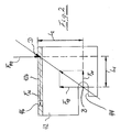
- the lengths L 1 and L 2 of the lever arms of the pretensioning forces F 18 and F 24 and the number of the respective belt types should be inversely proportional to each other.
- the length L 1 of the lever arm of the adjusting belts 18 should therefore be chosen to be half as long as the length L 2 of the lever arm of the drive belt 24 pointed out that this relationship is not realized in the representation according to FIG. 2.
- the bearing recess 44 in which the axis B is mounted is designed to be open on one side. Nevertheless, the axis B is held securely in this bearing recess 44, since neither the pretension force F 18 of the adjusting belt 18 nor the pretension force F 24 of the drive belt 24 has a component pointing out of this recess 44.
- the adjusting belt 18 and the drive belt 24 run essentially orthogonally to one another.
- the transfer device 10 is now actuated in order to lift a workpiece or a workpiece carrier from the conveyor belts of the conveyor section T 1 , ie if the lifting device 14 is extended in order to raise the lifting plate 12, the axis B also becomes due to the length invariance of the adjusting belt 18 raised. Since the drive axis C of the drive belt 24 is arranged in a stationary manner, and the drive belt 24 is also substantially length-invariant, the axis B in the simplest case, outlined in FIG. 3, executes a circular movement K around the drive axis C when the lifting plate 12 is raised.
- the entire tensioning device 32 is first, to be more precise the base plate 34 thereof via the guide rods from the lifting plate 12 taken. Furthermore, the guide strips 36 and Guide recesses 46 a linear compensatory movement in the direction of adjustment S. Finally, the guide recesses 46 are compared to dimension the cross-section of the guide strips 36 in such an oversize, that the carrier 42 not only linearly along the guide strips 36 can move up or down, but also about axis D can pivot without the risk of tilting or Blocking of the guide strips 36 in the guide recesses 46 existed. What is essential about this swiveling movement is that it is a component running orthogonal to the direction of adjustment S. be noted is that only the linear and the pivoting compensatory movement too a change in the bias of the spring 40 leads.
- the circular movement K is thus superimposed on a linear one Entraining movement (in direction S), as well as a linear (in Actuating direction S) and a pivoting (around axis D) compensating movement approximated.
- This way the length of the straps is needed 18 and 24 not to be changed during the lifting movement H of the lifting plate 12.
- Only the pretension of the belts 18 and 24 changes to the extent in which the spring force of the spring 40 also varies. This change in spring force but is due to the fact that they are only from the compensatory movements is caused, but not by the entire movement the base plate 34 of the clamping device 32, anyway small, and can furthermore, without further ado, by using a preloaded spring be minimized.
Landscapes
- Engineering & Computer Science (AREA)
- Mechanical Engineering (AREA)
- Devices For Conveying Motion By Means Of Endless Flexible Members (AREA)
- Structure Of Belt Conveyors (AREA)
Abstract
Description
- Fig. 1
- eine perspektivische Ansicht einer Umsetzvorrichtung, die mit einer erfindungsgemäßen Spannvorrichtung ausgestattet ist;
- Fig. 2
- eine schematische Seitenansicht des Trägers der erfindungsgemäßen Spannvorrichtung zur Erläuterung der an diesem Träger angreifenden Kräfte; und
- Fig. 3
- eine schematische Darstellung des Verlaufs der ersten und zweiten Riemen zur Erläuterung des grundlegenden Funktionsprinzips der erfindungsgemäßen Spannvorrichtung.
Claims (13)
- Vorrichtung (32) zum Spannen wenigstens zweier, im Wesentlichen längeninvarianter Riemen (18, 24),
wobei ein erster Riemen (18) um eine erste Achse (A) herumgeführt ist, welche wiederholt eine Stellbewegung in einer zur Achsrichtung der ersten Achse (A) im Wesentlichen orthogonal verlaufenden Stellrichtung (S) ausführt, und
wobei der erste Riemen (18) und ein zweiter Riemen (24) um eine gemeinsame zweite Achse (B) herumgeführt sind, wobei die Vorspannrichtungen (V18, V24) des ersten Riemens (18) und des zweiten Riemens (24) im Bereich der zweiten Achse (B) einen von 0° und 180° verschiedenen Winkel miteinander einschließen,
dadurch gekennzeichnet, dass der zweiten Achse (B) eine Federeinheit (40) zugeordnet ist, welche sie im Sinne des Spannens des ersten Riemens (18) und des zweiten Riemens (24) vorspannt und welche bei einer Stellbewegung der ersten Achse (A) eine Ausgleichsbewegung der zweiten Achse (B) aus den durch die Achsrichtung der zweiten Achse (B) mit den Vorspannrichtungen (V18, V24) des ersten Riemens (18) und des zweiten Riemens (24) jeweils vor Beginn der Stellbewegung aufgespannten Ebenen heraus zulässt. - Spannvorrichtung nach Anspruch 1,
dadurch gekennzeichnet, dass die erste Achse (A) an einem relativ zu einer Basiseinheit (26) verstellbaren Rahmen (12/30) gelagert ist, und dass die zweite Achse (B) an einem Träger (42) gelagert ist, der an dem Rahmen (12/30) relativ zu diesem verlagerbar geführt ist, wobei die Federeinheit (40) einenends mittelbar oder unmittelbar an dem Rahmen (12/30) und andernends mittelbar oder unmittelbar an dem Träger (42) abgestützt ist. - Spannvorrichtung nach Anspruch 2,
dadurch gekennzeichnet, dass eine an dem Rahmen (12/30) befestigbare bzw. befestigte Grundplatte (34) der Spannvorrichtung oder/und der Träger (42) aus Blech, vorzugsweise Metallblech, gefertigt ist. - Spannvorrichtung nach einem der Ansprüche 1 bis 3,
dadurch gekennzeichnet, dass wenigstens ein Lager der zweiten Achse (B) als einseitig offene Ausnehmung (44) ausgebildet ist. - Spannvorrichtung nach einem der Ansprüche 2 bis 4,
dadurch gekennzeichnet, dass an einem (34) der Teile, Grundplatte oder Träger, wenigstens eine Führungsleiste (36) und am jeweils anderen Teil (42), Träger oder Grundplatte, jeweils eine zugehörige Führungsausnehmung (46) vorgesehen ist. - Spannvorrichtung nach Anspruch 5,
dadurch gekennzeichnet, dass die Führungsleiste (46) im Wesentlichen orthogonal zur Vorspannrichtung (V24) des zweiten Riemens (24) vor Beginn der Stellbewegung verläuft, und dass die Führungsausnehmung (46) bezüglich der Abmessungen der sie durchsetzenden Führungsleiste (36) mit so großem Übermaß bemessen ist, dass der Träger (42) um eine zur zweiten Achse (B) im Wesentlichen parallel verlaufende Achse (D) verschwenkbar ist. - Spannvorrichtung nach einem der Ansprüche 1 bis 6,
dadurch gekennzeichnet, dass die Riemen (18, 24) eine Einlage aus zugfestem Material, insbesondere Glasfaser-Material, aufweisen. - Spannvorrichtung nach einem der Ansprüche 1 bis 7,
dadurch gekennzeichnet, dass die Riemen (18, 24) Zahnriemen sind. - Spannvorrichtung nach einem der Ansprüche 1 bis 8,
dadurch gekennzeichnet, dass die Federeinheit wenigstens eine Schraubendruckfeder (40) oder/und wenigstens eine Schraubenzugfeder oder/und wenigstens eine Gasfeder umfasst. - Spannvorrichtung nach einem der Ansprüche 1 bis 9,
dadurch gekennzeichnet, dass an der Grundplatte (34) oder/und dem Träger (42) ein Haltedorn (38) zum Halten der Schraubenfeder (40) vorgesehen ist. - Spannvorrichtung nach einem der Ansprüche 1 bis 10,
dadurch gekennzeichnet, dass an der Grundplatte (34) oder/und dem Träger (42) wenigstens ein Anschlag (38a) zur Begrenzung der Relativbewegung zwischen Grundplatte (34) und Träger (42) vorgesehen ist. - Spannvorrichtung nach einem der Ansprüche 1 bis 11,
dadurch gekennzeichnet, dass die Lage des Angriffs der Federeinheit (40) am Träger (42) relativ zur Lage der zweiten Achse (B) unter Berücksichtigung der Vorspannrichtungen (V18, V24) des wenigstens einen ersten Riemens (18) und des wenigstens einen zweiten Riemens (24) sowie unter Berücksichtigung der Anzahl erster Riemen (18) und der Anzahl zweiter Riemen (24) derart gewählt ist, dass die Vorspannkraft aller Riemen (18, 24) im Wesentlichen gleich groß ist. - Vorrichtung (10) zum Umsetzen von Werkstücken bzw. Werkstückträgern, umfassend eine Spannvorrichtung (32) nach einem der vorhergehenden Ansprüche.
Applications Claiming Priority (2)
| Application Number | Priority Date | Filing Date | Title |
|---|---|---|---|
| DE10159838 | 2001-12-06 | ||
| DE10159838A DE10159838C1 (de) | 2001-12-06 | 2001-12-06 | Umsetzvorrichtung mit einer Spannvorrichtung |
Publications (2)
| Publication Number | Publication Date |
|---|---|
| EP1318088A1 true EP1318088A1 (de) | 2003-06-11 |
| EP1318088B1 EP1318088B1 (de) | 2004-04-21 |
Family
ID=7708192
Family Applications (1)
| Application Number | Title | Priority Date | Filing Date |
|---|---|---|---|
| EP02027201A Expired - Lifetime EP1318088B1 (de) | 2001-12-06 | 2002-12-05 | Spannvorrichtung und Umsetzvorrichtung mit einer derartigen Spannvorrichtung |
Country Status (3)
| Country | Link |
|---|---|
| US (1) | US6884193B2 (de) |
| EP (1) | EP1318088B1 (de) |
| DE (2) | DE10159838C1 (de) |
Cited By (1)
| Publication number | Priority date | Publication date | Assignee | Title |
|---|---|---|---|---|
| DE102018204644A1 (de) | 2018-03-27 | 2019-10-02 | Robert Bosch Gmbh | Hub- und Fördervorrichtung und Streckenförderer mit der Hub- und Fördervorrichtung |
Families Citing this family (3)
| Publication number | Priority date | Publication date | Assignee | Title |
|---|---|---|---|---|
| DE202011000071U1 (de) | 2011-01-12 | 2012-04-17 | Usk Karl Utz Sondermaschinen Gmbh | Transportsystem für insbesondere plattenförmige Werkstücke wie Wafer/Solarzellen und dergleichen |
| DE102013215753A1 (de) * | 2013-08-09 | 2015-02-12 | Robert Bosch Gmbh | Vorrichtung zum Umsetzen von Werkstückträgern mit Gleitführung |
| DE102015122363B4 (de) * | 2015-12-21 | 2020-03-12 | Festo Ag & Co. Kg | Zahnriemenspannsystem |
Citations (5)
| Publication number | Priority date | Publication date | Assignee | Title |
|---|---|---|---|---|
| US3067851A (en) * | 1961-03-07 | 1962-12-11 | Bostitch Inc | Article feeding device |
| DE3012355A1 (de) * | 1980-03-29 | 1981-10-08 | Robert Bosch Gmbh, 7000 Stuttgart | Vorrichtung zum umsetzen bei transportbaendern |
| DE4124763A1 (de) * | 1991-07-23 | 1993-01-28 | Mannesmann Ag | Ablenkvorrichtung fuer stueckgut |
| DE4439106C1 (de) * | 1994-11-02 | 1996-05-30 | Bosch Gmbh Robert | Vorrichtung zum Umsetzen von Förderteilen |
| DE19603554A1 (de) * | 1996-02-01 | 1997-08-07 | Bosch Gmbh Robert | Vorrichtung zum Umsetzen von Werkstücken bzw. Werkstückträgern |
Family Cites Families (8)
| Publication number | Priority date | Publication date | Assignee | Title |
|---|---|---|---|---|
| DE131278C (de) | ||||
| US3494210A (en) | 1968-10-29 | 1970-02-10 | Massey Ferguson Ind Ltd | Automatic belt tensioner |
| DD131278B1 (de) * | 1977-03-14 | 1980-08-27 | Gotthard Lange | Riemenspanneinrichtung fuer stufenlos einstellbare keil |
| US4648774A (en) * | 1983-02-28 | 1987-03-10 | Methods, Inc. | Load/unload apparatus for disc-like workpieces |
| USRE34311E (en) * | 1984-08-30 | 1993-07-13 | Texas Instruments Incorporated | Semiconductor slice cassette transport unit |
| JPS6374581A (ja) * | 1986-09-17 | 1988-04-05 | トキコ株式会社 | 電動ロボツト |
| DE3731280A1 (de) * | 1987-09-17 | 1989-03-30 | Maho Ag | Werkzeugwechsler fuer universal-fraes- und bohrmaschinen |
| US6354167B1 (en) * | 2000-06-26 | 2002-03-12 | The United States Of America As Represented By The Secretary Of The Navy | Scara type robot with counterbalanced arms |
-
2001
- 2001-12-06 DE DE10159838A patent/DE10159838C1/de not_active Expired - Fee Related
-
2002
- 2002-12-03 US US10/308,444 patent/US6884193B2/en not_active Expired - Lifetime
- 2002-12-05 DE DE50200371T patent/DE50200371D1/de not_active Expired - Lifetime
- 2002-12-05 EP EP02027201A patent/EP1318088B1/de not_active Expired - Lifetime
Patent Citations (5)
| Publication number | Priority date | Publication date | Assignee | Title |
|---|---|---|---|---|
| US3067851A (en) * | 1961-03-07 | 1962-12-11 | Bostitch Inc | Article feeding device |
| DE3012355A1 (de) * | 1980-03-29 | 1981-10-08 | Robert Bosch Gmbh, 7000 Stuttgart | Vorrichtung zum umsetzen bei transportbaendern |
| DE4124763A1 (de) * | 1991-07-23 | 1993-01-28 | Mannesmann Ag | Ablenkvorrichtung fuer stueckgut |
| DE4439106C1 (de) * | 1994-11-02 | 1996-05-30 | Bosch Gmbh Robert | Vorrichtung zum Umsetzen von Förderteilen |
| DE19603554A1 (de) * | 1996-02-01 | 1997-08-07 | Bosch Gmbh Robert | Vorrichtung zum Umsetzen von Werkstücken bzw. Werkstückträgern |
Cited By (2)
| Publication number | Priority date | Publication date | Assignee | Title |
|---|---|---|---|---|
| DE102018204644A1 (de) | 2018-03-27 | 2019-10-02 | Robert Bosch Gmbh | Hub- und Fördervorrichtung und Streckenförderer mit der Hub- und Fördervorrichtung |
| US10669100B2 (en) | 2018-03-27 | 2020-06-02 | Robert Bosch Gmbh | Lifting and conveying device and section conveyor having the lifting and conveying device |
Also Published As
| Publication number | Publication date |
|---|---|
| DE10159838C1 (de) | 2003-07-17 |
| US6884193B2 (en) | 2005-04-26 |
| US20030109341A1 (en) | 2003-06-12 |
| EP1318088B1 (de) | 2004-04-21 |
| DE50200371D1 (de) | 2004-05-27 |
Similar Documents
| Publication | Publication Date | Title |
|---|---|---|
| DE60223877T2 (de) | Spannungsregelvorrichtung für Kettensäge | |
| DE68904389T2 (de) | Gurtspanner. | |
| DE102010019284B4 (de) | Riementrieb zur Umsetzung einer Drehbewegung in eine Linearbewegung | |
| EP3028964B1 (de) | Rollenmodul mit förderrollen und mitnahmerollen | |
| EP2842889A1 (de) | Vorrichtung zum Umsetzen von Werkstückträgern mit Gleitführung | |
| DE19805878A1 (de) | Vorrichtung zum Reduzieren der Kettenspannung | |
| EP0732476B1 (de) | Antriebseinrichtung | |
| EP1318088B1 (de) | Spannvorrichtung und Umsetzvorrichtung mit einer derartigen Spannvorrichtung | |
| DE3534446A1 (de) | Brennkraftmaschine mit zwei nebeneinander angeordneten nockenwellen | |
| DE102004032514A1 (de) | Spulenrahmen Be- und Entlastungsvorrichtung für eine Spuleinrichtung einer Kreuzspulen herstellenden Textilmaschine | |
| DE1952478B2 (de) | Automatische Riemenspannvorrichtung für ein stufenlos einstellbares Keilriemengetriebe | |
| EP0386551B1 (de) | Verstelleinrichtung | |
| EP2735535B1 (de) | Fadenführereinheit, Bewegungsdämpfer für eine Fadenführereinheit sowie Verfahren zum Herstellen des Bewegungsdämpfers | |
| DE68917780T2 (de) | Automatische Spannvorrichtung für ein in einer biegsamen Hülle geführtes Zugkabel. | |
| DE3327266A1 (de) | Verschiebungsmessinstrument | |
| EP0941429A1 (de) | Antrieb, vorzugsweise torantrieb | |
| DE2720673B2 (de) | Vorrichtung zum ungleichförmigen Spannen eines Gummituches in einer Offsetdruckmaschine | |
| DE69313615T2 (de) | Mit einem Kabel betätigte Fahrzeugfesterhebervorrichtung | |
| EP0853201A1 (de) | Vorrichtung zum automatischen, stufenweisen Seillängenausgleich eines Bowdenzugsystems | |
| DE10242291A1 (de) | Messerhalter mit mechanischer Schnittkrafteinstellung | |
| DE3932798A1 (de) | Riemenspanner | |
| DE102014219417B4 (de) | Antriebseinrichtung mit Elektromotor für ein Gurtschloss einer Sicherheitsgurteinrichtung | |
| DE69803929T2 (de) | Transportvorrichtung für leiterrahmen und transportanordnung | |
| EP1081463B1 (de) | Wegmesssystem | |
| DE3940047C2 (de) | Riemenandrückvorrichtung, insbesondere an einer Offen-End-Spinnmaschine |
Legal Events
| Date | Code | Title | Description |
|---|---|---|---|
| PUAI | Public reference made under article 153(3) epc to a published international application that has entered the european phase |
Free format text: ORIGINAL CODE: 0009012 |
|
| AK | Designated contracting states |
Designated state(s): AT BE BG CH CY CZ DE DK EE ES FI FR GB GR IE IT LI LU MC NL PT SE SI SK TR |
|
| AX | Request for extension of the european patent |
Extension state: AL LT LV MK RO |
|
| GRAP | Despatch of communication of intention to grant a patent |
Free format text: ORIGINAL CODE: EPIDOSNIGR1 |
|
| 17P | Request for examination filed |
Effective date: 20030611 |
|
| GRAS | Grant fee paid |
Free format text: ORIGINAL CODE: EPIDOSNIGR3 |
|
| AKX | Designation fees paid |
Designated state(s): CH DE FR LI |
|
| GRAA | (expected) grant |
Free format text: ORIGINAL CODE: 0009210 |
|
| AK | Designated contracting states |
Kind code of ref document: B1 Designated state(s): CH DE FR LI |
|
| REG | Reference to a national code |
Ref country code: CH Ref legal event code: NV Representative=s name: A. BRAUN, BRAUN, HERITIER, ESCHMANN AG PATENTANWAE Ref country code: CH Ref legal event code: EP |
|
| REG | Reference to a national code |
Ref country code: IE Ref legal event code: FG4D Free format text: GERMAN |
|
| REF | Corresponds to: |
Ref document number: 50200371 Country of ref document: DE Date of ref document: 20040527 Kind code of ref document: P |
|
| REG | Reference to a national code |
Ref country code: IE Ref legal event code: FD4D |
|
| ET | Fr: translation filed | ||
| PLBE | No opposition filed within time limit |
Free format text: ORIGINAL CODE: 0009261 |
|
| STAA | Information on the status of an ep patent application or granted ep patent |
Free format text: STATUS: NO OPPOSITION FILED WITHIN TIME LIMIT |
|
| 26N | No opposition filed |
Effective date: 20050124 |
|
| REG | Reference to a national code |
Ref country code: CH Ref legal event code: PFA Owner name: BOSCH REXROTH AKTIENGESELLSCHAFT Free format text: BOSCH REXROTH AKTIENGESELLSCHAFT#LAUTENSCHLAGER STR. 17#70173 STUTTGART (DE) -TRANSFER TO- BOSCH REXROTH AKTIENGESELLSCHAFT#LAUTENSCHLAGER STR. 17#70173 STUTTGART (DE) |
|
| REG | Reference to a national code |
Ref country code: CH Ref legal event code: PCAR Free format text: NEW ADDRESS: HOLBEINSTRASSE 36-38, 4051 BASEL (CH) |
|
| REG | Reference to a national code |
Ref country code: FR Ref legal event code: PLFP Year of fee payment: 14 |
|
| REG | Reference to a national code |
Ref country code: FR Ref legal event code: PLFP Year of fee payment: 15 |
|
| REG | Reference to a national code |
Ref country code: FR Ref legal event code: PLFP Year of fee payment: 16 |
|
| PGFP | Annual fee paid to national office [announced via postgrant information from national office to epo] |
Ref country code: FR Payment date: 20211220 Year of fee payment: 20 |
|
| PGFP | Annual fee paid to national office [announced via postgrant information from national office to epo] |
Ref country code: CH Payment date: 20211222 Year of fee payment: 20 |
|
| PGFP | Annual fee paid to national office [announced via postgrant information from national office to epo] |
Ref country code: DE Payment date: 20220224 Year of fee payment: 20 |
|
| REG | Reference to a national code |
Ref country code: DE Ref legal event code: R071 Ref document number: 50200371 Country of ref document: DE |
|
| REG | Reference to a national code |
Ref country code: CH Ref legal event code: PL |