EP1316490B1 - Direction électrique pour véhicules - Google Patents
Direction électrique pour véhicules Download PDFInfo
- Publication number
- EP1316490B1 EP1316490B1 EP02025477A EP02025477A EP1316490B1 EP 1316490 B1 EP1316490 B1 EP 1316490B1 EP 02025477 A EP02025477 A EP 02025477A EP 02025477 A EP02025477 A EP 02025477A EP 1316490 B1 EP1316490 B1 EP 1316490B1
- Authority
- EP
- European Patent Office
- Prior art keywords
- vehicle
- handles
- steering
- control
- driver
- Prior art date
- Legal status (The legal status is an assumption and is not a legal conclusion. Google has not performed a legal analysis and makes no representation as to the accuracy of the status listed.)
- Expired - Lifetime
Links
- 238000006073 displacement reaction Methods 0.000 claims description 21
- 230000033001 locomotion Effects 0.000 claims description 8
- 230000009977 dual effect Effects 0.000 claims description 3
- 230000001133 acceleration Effects 0.000 description 6
- 238000005516 engineering process Methods 0.000 description 4
- 238000010586 diagram Methods 0.000 description 3
- 238000012937 correction Methods 0.000 description 2
- 230000002459 sustained effect Effects 0.000 description 2
- 241001282135 Poromitra oscitans Species 0.000 description 1
- 206010048232 Yawning Diseases 0.000 description 1
- 230000005540 biological transmission Effects 0.000 description 1
- 238000012508 change request Methods 0.000 description 1
- 230000006835 compression Effects 0.000 description 1
- 238000007906 compression Methods 0.000 description 1
- 230000001627 detrimental effect Effects 0.000 description 1
- 210000000056 organ Anatomy 0.000 description 1
- 210000003813 thumb Anatomy 0.000 description 1
Images

Classifications
-
- B—PERFORMING OPERATIONS; TRANSPORTING
- B62—LAND VEHICLES FOR TRAVELLING OTHERWISE THAN ON RAILS
- B62D—MOTOR VEHICLES; TRAILERS
- B62D1/00—Steering controls, i.e. means for initiating a change of direction of the vehicle
- B62D1/02—Steering controls, i.e. means for initiating a change of direction of the vehicle vehicle-mounted
-
- B—PERFORMING OPERATIONS; TRANSPORTING
- B62—LAND VEHICLES FOR TRAVELLING OTHERWISE THAN ON RAILS
- B62D—MOTOR VEHICLES; TRAILERS
- B62D5/00—Power-assisted or power-driven steering
- B62D5/001—Mechanical components or aspects of steer-by-wire systems, not otherwise provided for in this maingroup
- B62D5/005—Mechanical components or aspects of steer-by-wire systems, not otherwise provided for in this maingroup means for generating torque on steering wheel or input member, e.g. feedback
-
- B—PERFORMING OPERATIONS; TRANSPORTING
- B62—LAND VEHICLES FOR TRAVELLING OTHERWISE THAN ON RAILS
- B62D—MOTOR VEHICLES; TRAILERS
- B62D7/00—Steering linkage; Stub axles or their mountings
- B62D7/06—Steering linkage; Stub axles or their mountings for individually-pivoted wheels, e.g. on king-pins
- B62D7/14—Steering linkage; Stub axles or their mountings for individually-pivoted wheels, e.g. on king-pins the pivotal axes being situated in more than one plane transverse to the longitudinal centre line of the vehicle, e.g. all-wheel steering
- B62D7/15—Steering linkage; Stub axles or their mountings for individually-pivoted wheels, e.g. on king-pins the pivotal axes being situated in more than one plane transverse to the longitudinal centre line of the vehicle, e.g. all-wheel steering characterised by means varying the ratio between the steering angles of the steered wheels
- B62D7/1509—Steering linkage; Stub axles or their mountings for individually-pivoted wheels, e.g. on king-pins the pivotal axes being situated in more than one plane transverse to the longitudinal centre line of the vehicle, e.g. all-wheel steering characterised by means varying the ratio between the steering angles of the steered wheels with different steering modes, e.g. crab-steering, or steering specially adapted for reversing of the vehicle
Definitions
- the present invention relates to the control of change of trajectory of a motor vehicle.
- the steering control of a passenger car is mostly done by means of a steering wheel.
- the driver rotates the steering wheel one way or the other to steer the vehicle in one direction or another. In this way, the driver gives a yawing motion to the vehicle.
- electric control means for all the actuators of a motor vehicle, including the steering. This technology is known by the Anglo-Saxon name "steer by wire”.
- the actuator control technology by electrical connection is to replace by electrical connections the current links usually hydraulic or mechanical between the control and the actuators.
- the steering control available to the driver of the vehicle may be a traditional steering wheel or a joystick like broomstick.
- At the wheels there is an electric actuator, preferably individual wheel by wheel.
- the orders printed by the driver of the vehicle on his control means are sent to the actuators by an electrical connection, all being placed under the control of a trajectory controller loaded with adequate programs to be able to drive the actuators appropriately.
- the advantage of this technology is that it is ideally matched with the progress of the electronics, which allows more and more sophisticated servo-control and which makes it possible to place the steering of the wheels not only under the control of the manual control but also under the control of a security system. For example, it is possible to print on the steering wheels an angle which takes into account not only the driver's control of the vehicle, but which also takes into account dynamic parameters observed on the vehicle.
- the first need is to take a turn and, in this case, it is necessary to print a lace acceleration to the vehicle, followed by a phase where the yaw rate varies little, then a yaw rate deceleration at the end of the turn, in order to obtain a different direction of movement after the maneuver compared to what it was before the maneuver.
- the present invention therefore aims to provide an electrical system for acting on the path of a vehicle of which all the wheels are steered, the steering angle being imposed individually and selectively on each of the steering wheels by a dedicated electric actuator, said electrical system comprising a control member for acting on the trajectory of the vehicle, said control member being at the disposal of the driver, comprising a trajectory controller determining for each of the steering wheels a wheel steering angle according to at least one signal delivered by the vehicle trajectory control member and as a function of at least one signal representative of the effective trajectory of the vehicle.
- the trajectory controller is programmed to ensure consistency between the trajectory desired by the driver, by its actions on the control member, and the effective trajectory as it can be observed by adequate sensors (for example a longitudinal speed sensor, a transverse acceleration sensor, a yaw sensor).
- the present invention also aims, independently of the previous objective, to make available to the driver of the vehicle a specific command, to cause a transverse translation of the vehicle constant heading, this command being independent of the control of change of direction of the vehicle, ie independent of the yaw control (change of course).
- US Patent 5,492,348 proposes a steering control offering four different modes for steering.
- the patent application DE 44 04 594 proposes a joystick-type control device that can act on the steering and on the transverse displacement separately, but this type of control is very different from a steering wheel.
- the objective is to offer a command that is as little confusing as possible for a driver already accustomed to using a steering wheel to act on the trajectory of his vehicle, while providing a potential for progress.
- the present invention retains the use of a first member of the "flying" type for printing direction changes to the vehicle.
- a change of direction corresponds to a change of course.
- the steering commands of the vehicle are done conventionally, that is to say by printing a rotation to this first body.
- the present invention proposes to equip the control device with a second specific member for printing the vehicle with a transversal displacement at constant heading (ie without lace).
- the invention also relates to a control device available to the driver to act on the path of a vehicle with all the wheels are directed by a dual control acting separately on the yawning and the transverse displacement pure, the transmission of the displacement orders being done electrically, the device comprising a first control member for printing a yaw movement to the vehicle, the first member essentially comprising a rotary shaft integral with two handles disposed at a distance from the rotary shaft, said rotary shaft being provided with at least one sensor ... rotation angle and a return means in a straight line position, and having a second member for printing the vehicle a transverse displacement without lace.
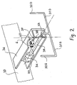
- FIG 1 there is shown a driver seat 1, a dashboard 2 and the control device of the trajectory 3 proposed by the invention.
- a central portion 30 connected to a shaft 33 (see Figure 2), the central portion 30 may contain an air bag as usual steering wheels.
- two branches 31G and 31D, extended by two handles 32G and 32D, are arranged at a distance from the rotary shaft 33 and preferably substantially symmetrical with respect thereto.
- the rotary shaft 33 is provided with at least one rotation angle sensor 34 and a return means 35 in the straight-line position.
- a box 36 belonging to the rigid structure 10 of the vehicle terminates in a base 37, the base forming bearings for an axle 38 rotatably mounted on the ends of the base 37.
- This axle 38 is also integral with the shaft.
- a link 4 equipped with a force sensor 40 extension / compression connects the sheath 39 to box 36.
- the driver's action is identical to what he would do with an existing passenger car today. It turns the handles 32G and 32D clockwise to turn right, and counterclockwise to turn left, as shown by the arrows F1 in Figure 1.
- the rotation is limited to a value much less than + 90 ° or -90 °.
- the rotation covers for example the range from -30 ° to + 30 °
- the handles 32G and 32D are essentially the first controller.
- the 32G and 32D handles are a strong action lever comparable to a traditional steering wheel where the driver prints an angle variation corresponding to a demand for variation of the yaw rate.
- the control device available to the driver comprises a second member for acting on the path of the vehicle, through which it can express a demand for transverse displacement constant cap.
- this second member comprises at least one force sensor arranged to detect a bias tending to weigh on said handles around a tilting axis substantially perpendicular to the rotary shaft, said tilting axis being preferably substantially within the plane of symmetry of the first member.
- the shaft 33 is arranged rather horizontally, ie as the steering column of the current passenger vehicles.
- this effort does not cause any displacement, but there is preferably a minimum threshold to be exceeded before modifying the trajectory. This effort is measured by the sensor 40.
- a minimum threshold to be exceeded before modifying the trajectory.
- This effort is measured by the sensor 40.
- the second member for acting on the path of the vehicle comprises at least one sensitive trigger, for example one on each handle, actuating one the transverse displacement constant cap in one direction and the other the transverse displacement constant cap in the other direction, depending on the amplitude of the pressure exerted on the trigger.
- the orientation of the shaft 33 is rather horizontal, contrary to what has been indicated above.
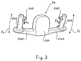
- FIG 3 we see an embodiment of a control of the trajectory 3b according to this second embodiment of the invention '.
- Several parts are very similar to what is found in the first embodiment, namely a central portion 30b, two branches 31bG and 31bD, extended by two handles 32bG and 32bD.
- a trigger 4bG and respectively 4bD disposed at a location chosen to be easily actuated voluntarily by the thumb, without the risk of being involuntarily actuated for example during a rotation of the control 3b.
- the action of the driver is identical to what was explained above.
- the driver acts on either of the triggers 4bG or 4bD.
- the trigger 4bG or 4bD For example, to move the vehicle transversely to the left, he squeezes the trigger 4bG, while to move the vehicle transversely to the right, he presses the trigger 4bD.
- This action on either of the triggers 4bG or 4bD can of course be combined with a rotation of the control 3b to combine a certain degree of transverse displacement and a course change request.
- the command printed by the driver (arrows F2 in FIG. 1 or action F3 on one of the keys 4bG or 4bD in FIG. 3) is translated in such a way that all the wheels of the vehicle turn in the same direction and at the same angle. More generally, in the case of a request for transverse translation without a request for a course change, whether or not the vehicle is making a change of course, the variation of the steering angle is identical on all the wheels of the vehicle. Therefore, the command printed by the driver (arrows F2 in FIG. 1 or action F3 on one of the keys 4bG or 4bD in FIG.
- both the rotation schematized by the arrows F1 as the control shown schematically by the arrows F2 or F3 are sent to a trajectory controller (not shown) loaded with adequate programs to to be able to drive the electric actuators at the steering wheels, preferably individually wheel by wheel.
- a trajectory controller (not shown) loaded with adequate programs to to be able to drive the electric actuators at the steering wheels, preferably individually wheel by wheel.
- the reduction between the rotation of the handles 32G and 32D (control according to the arrows F1) and the steering of the wheels is variable depending on the longitudinal movement speed of the vehicle, which the trajectory controller can easily take into account.
- the trajectory controller may superimpose any corrections determined by a trajectory control function such as that provided by an ESP system, and / or as that resulting from a dialogue with a means for controlling traffic outside the vehicle and / or a dialogue with a means of locating the GPS-type vehicle.
- the trajectory corrector determines the steering angle for each of the wheels accordingly.
- the steering angle of each wheel comprises a component resulting from the orders printed by the driver of the vehicle on his control means and a correction component.
- the pilot When traveling at a sustained speed, the pilot expresses requests for a change of trajectory with or without variation of the yaw rate, the two of course being able to be combined, for example, for an overtaking in a turn.
- the present invention makes it possible to offer control latitude of additional trajectories while maintaining the usual means of controlling the change of direction of the vehicle.
- the driver not used to this additional command may very well not use it and act only by printing rotations driving.
- an actuator for each steered wheel In an electrical system for acting on the path of a multiple steered wheel vehicle, preferably, there is an actuator for each steered wheel.
- a controller selectively imposes an appropriate steering angle for each of the steered wheels based at least on the location of said steered wheel on the vehicle, the vehicle speed and the requested course change.
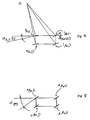
- Figure 4 illustrates the case of a yaw movement at a sustained speed.
- the location of the various steering wheels is indicated on the vehicle: left front steering wheel 1AvG, right front steering wheel 1AvD, left rear steering wheel 1ArG and right rear steering wheel 1ArD.
- left front steering wheel 1AvG right front steering wheel 1AvD
- left rear steering wheel 1ArG left rear steering wheel 1ArD
- right rear steering wheel 1ArD right rear steering wheel
- the trajectory controller controlling the steering angle selectively wheel by wheel can, from at least one signal delivered by the control device (for example a signal representative of the steering wheel angle imposed by the vehicle driver) and taking into account other relevant parameters (such as the longitudinal speed of movement of the vehicle), determine the spatial location of the instantaneous center of rotation ideal for the vehicle. This instantaneous center of rotation is identified by the point ⁇ .
- the trajectory controller calculates the steering angle of each of the wheels so that the plane of the wheel is substantially perpendicular to the line connecting the center of the wheel considered instantaneous center of rotation of the vehicle ⁇
- the trajectory controller is loaded with the appropriate programs to perform this calculation.
- Figure 5 illustrates the case of a change of trajectory by transverse displacement at constant heading. This time, we see that all the wheels point at the same angle ⁇ (T) .
- the invention also extends to an electric steering system for a vehicle of which only some wheels are steered. Compared to FIG. 4, the difference is of course that the angle ⁇ Ar is zero on the left and on the right. But this is only a particular case of the system explained above, in which the trajectory controller, steering the steering angle selectively wheel by wheel to the steering axle can, from the steering angle imposed by the driver of the vehicle and taking into account other relevant parameters such as the speed of longitudinal displacement of the vehicle, determining the spatial location of the instantaneous center of rotation ideal for the vehicle (point ⁇ ), this time necessarily located on the virtual line linking the center rear wheels.
- the invention proposes an electrical system for acting on the trajectory of a vehicle, all the steering wheels of which are controlled by an electric actuator of its own, the steering angle being imposed individually and selectively on each of the steering wheels. by its electric actuator, the system comprising a control member for acting on the trajectory of the vehicle, said control member being at the disposal of the driver, comprising a trajectory controller determining the spatial location of the instantaneous center of rotation of the vehicle as a function of at least one signal delivered by said organ of control and as a function of at least one signal representative of the effective trajectory of the vehicle, for example the longitudinal speed of the vehicle, and calculating the steering angle of each of the wheels so that the plane of the wheel is substantially perpendicular to the line connecting the center of the wheel considered instantaneous center of rotation of the vehicle ⁇ .
Landscapes
- Engineering & Computer Science (AREA)
- Chemical & Material Sciences (AREA)
- Combustion & Propulsion (AREA)
- Transportation (AREA)
- Mechanical Engineering (AREA)
- Steering Control In Accordance With Driving Conditions (AREA)
- Steering Controls (AREA)
- Steering-Linkage Mechanisms And Four-Wheel Steering (AREA)
- Handcart (AREA)
- Conductive Materials (AREA)
- Power Steering Mechanism (AREA)
- Switch Cases, Indication, And Locking (AREA)
Applications Claiming Priority (4)
| Application Number | Priority Date | Filing Date | Title |
|---|---|---|---|
| FR0115222 | 2001-11-23 | ||
| FR0115222A FR2832682A1 (fr) | 2001-11-23 | 2001-11-23 | Dispositif de commande pour direction electrique active |
| FR0205662 | 2002-05-03 | ||
| FR0205662A FR2839291A1 (fr) | 2002-05-03 | 2002-05-03 | Direction electrique active |
Publications (3)
| Publication Number | Publication Date |
|---|---|
| EP1316490A2 EP1316490A2 (fr) | 2003-06-04 |
| EP1316490A3 EP1316490A3 (fr) | 2003-10-08 |
| EP1316490B1 true EP1316490B1 (fr) | 2006-03-15 |
Family
ID=26213277
Family Applications (1)
| Application Number | Title | Priority Date | Filing Date |
|---|---|---|---|
| EP02025477A Expired - Lifetime EP1316490B1 (fr) | 2001-11-23 | 2002-11-15 | Direction électrique pour véhicules |
Country Status (5)
| Country | Link |
|---|---|
| EP (1) | EP1316490B1 (enExample) |
| JP (1) | JP4026131B2 (enExample) |
| CN (1) | CN1281450C (enExample) |
| AT (1) | ATE320367T1 (enExample) |
| DE (1) | DE60209847T2 (enExample) |
Families Citing this family (19)
| Publication number | Priority date | Publication date | Assignee | Title |
|---|---|---|---|---|
| NL1015626C2 (nl) * | 2000-05-18 | 2001-11-20 | Skf Eng & Res Centre Bv | Stuurinrichting voor een elektrisch bestuurd (drive-by-wire) voertuig. |
| DE102004063916A1 (de) * | 2004-01-21 | 2005-11-10 | TÜV Automotive GmbH TÜV SÜD Gruppe | Mehrspuriges Fahrzeug zum Durchführen von Crash-Versuchen |
| DE102004055282A1 (de) * | 2004-11-16 | 2006-06-01 | Mobil Elektronik Gmbh | Lenksystem für Fahrzeug |
| JP4581660B2 (ja) * | 2004-12-02 | 2010-11-17 | 日産自動車株式会社 | 車両用操舵装置 |
| JP4574407B2 (ja) * | 2005-03-24 | 2010-11-04 | 本田技研工業株式会社 | 操舵装置 |
| JP4528213B2 (ja) * | 2005-06-23 | 2010-08-18 | 本田技研工業株式会社 | 車両用操舵装置 |
| FR2887839B1 (fr) * | 2005-07-04 | 2007-09-14 | Conception & Dev Michelin Sa | Systeme de direction d'un vehicule comportant un mode de fonctionnement degrade en cas de panne d'un actionneur de braquage de roue. |
| DE102005038855A1 (de) | 2005-08-12 | 2007-02-15 | Takata-Petri Ag | Lenkradanordnung |
| US7631714B2 (en) * | 2006-06-27 | 2009-12-15 | Gordon Ewbank Dower | Motor vehicle steering control |
| FR2928130B1 (fr) * | 2008-02-29 | 2010-05-28 | Moulene | Vehicule motorise a inclinaison commandee. |
| JP5338968B2 (ja) * | 2010-02-25 | 2013-11-13 | トヨタ自動車株式会社 | 操舵制御装置 |
| JP4980445B2 (ja) * | 2010-05-17 | 2012-07-18 | 本田技研工業株式会社 | 操舵装置 |
| DE102011054947B4 (de) | 2011-10-31 | 2018-08-16 | Deutsches Zentrum für Luft- und Raumfahrt e.V. | Steuerungseinrichtung zur Fahrzeugsteuerung |
| DE102011118133A1 (de) * | 2011-11-10 | 2013-05-16 | Leopold Kostal Gmbh & Co. Kg | Lenkvorrichtung für ein Kraftfahrzeug |
| CN105753801B (zh) * | 2016-03-25 | 2018-06-01 | 浙江工业大学 | 一种均三嗪类化合物的制备方法 |
| DE102016115466B4 (de) | 2016-08-19 | 2021-02-11 | Thyssenkrupp Ag | Steuerhorn für die Lenkung eines Kraftfahrzeugs |
| CN106218703B (zh) * | 2016-09-12 | 2018-11-06 | 北京汽车股份有限公司 | 教练车、教练车转向系统及其控制方法 |
| DE102023104238A1 (de) * | 2023-02-21 | 2024-08-22 | Audi Aktiengesellschaft | Lenkeinrichtung für ein Kraftfahrzeug sowie entsprechendes Kraftfahrzeug |
| DE102023104237A1 (de) * | 2023-02-21 | 2024-08-22 | Audi Aktiengesellschaft | Lenkeinrichtung für ein Kraftfahrzeug sowie entsprechendes Kraftfahrzeug |
Citations (6)
| Publication number | Priority date | Publication date | Assignee | Title |
|---|---|---|---|---|
| US2203810A (en) * | 1939-06-26 | 1940-06-11 | Berry Wilbert Paul | Steering system for automobiles |
| US3198541A (en) * | 1962-06-18 | 1965-08-03 | Clark Equipment Co | Universal steering apparatus |
| DE3124181A1 (de) * | 1981-06-19 | 1983-01-05 | Thassilo Dr Med Schmidt | "lenkvorrichtung fuer lenkspindel fuer fahrzeuge insbesondere kraftfahrzeuge" |
| US5348111A (en) * | 1989-06-08 | 1994-09-20 | Group Lotus Plc | Wheeled vehicle steering system |
| DE4404594A1 (de) * | 1994-02-12 | 1995-08-17 | Dieter Wittelsberger | Bedieneinrichtung, deren Verwendung für ein Kraftfahrzeug und Kraftfahrzeug-Steuersystem |
| US5492348A (en) * | 1992-09-29 | 1996-02-20 | Shaw; David C. | Vehicle steering system |
Family Cites Families (4)
| Publication number | Priority date | Publication date | Assignee | Title |
|---|---|---|---|---|
| AUPM545594A0 (en) * | 1994-05-06 | 1994-05-26 | Spark, Ian James | Improved agricultural implement |
| FR2763284A1 (fr) | 1997-05-16 | 1998-11-20 | Conception & Dev Michelin Sa | Ensemble comportant une roue et une suspension integree a la roue |
| FR2763300A1 (fr) | 1997-05-16 | 1998-11-20 | Conception & Dev Michelin Sa | Vehicule comportant une suspension a variation de carrossage actif |
| WO2001070556A1 (de) * | 2000-03-20 | 2001-09-27 | Hubtex Maschinenbau Gmbh & Co. Kg | Mehrwegetransportfahrzeug, insbesondere mehrwegestapler |
-
2002
- 2002-11-15 DE DE60209847T patent/DE60209847T2/de not_active Expired - Lifetime
- 2002-11-15 AT AT02025477T patent/ATE320367T1/de not_active IP Right Cessation
- 2002-11-15 EP EP02025477A patent/EP1316490B1/fr not_active Expired - Lifetime
- 2002-11-22 CN CN02148895.9A patent/CN1281450C/zh not_active Expired - Fee Related
- 2002-11-25 JP JP2002340228A patent/JP4026131B2/ja not_active Expired - Fee Related
Patent Citations (6)
| Publication number | Priority date | Publication date | Assignee | Title |
|---|---|---|---|---|
| US2203810A (en) * | 1939-06-26 | 1940-06-11 | Berry Wilbert Paul | Steering system for automobiles |
| US3198541A (en) * | 1962-06-18 | 1965-08-03 | Clark Equipment Co | Universal steering apparatus |
| DE3124181A1 (de) * | 1981-06-19 | 1983-01-05 | Thassilo Dr Med Schmidt | "lenkvorrichtung fuer lenkspindel fuer fahrzeuge insbesondere kraftfahrzeuge" |
| US5348111A (en) * | 1989-06-08 | 1994-09-20 | Group Lotus Plc | Wheeled vehicle steering system |
| US5492348A (en) * | 1992-09-29 | 1996-02-20 | Shaw; David C. | Vehicle steering system |
| DE4404594A1 (de) * | 1994-02-12 | 1995-08-17 | Dieter Wittelsberger | Bedieneinrichtung, deren Verwendung für ein Kraftfahrzeug und Kraftfahrzeug-Steuersystem |
Also Published As
| Publication number | Publication date |
|---|---|
| CN1281450C (zh) | 2006-10-25 |
| CN1422776A (zh) | 2003-06-11 |
| JP2003165445A (ja) | 2003-06-10 |
| JP4026131B2 (ja) | 2007-12-26 |
| EP1316490A2 (fr) | 2003-06-04 |
| ATE320367T1 (de) | 2006-04-15 |
| DE60209847D1 (de) | 2006-05-11 |
| EP1316490A3 (fr) | 2003-10-08 |
| DE60209847T2 (de) | 2006-10-12 |
Similar Documents
| Publication | Publication Date | Title |
|---|---|---|
| EP1316490B1 (fr) | Direction électrique pour véhicules | |
| FR2832682A1 (fr) | Dispositif de commande pour direction electrique active | |
| EP1428740B1 (fr) | Système de direction d'un véhicule comportant un mode de fonctionnement dégradé en cas de panne d'un actionneur de braquage de roue | |
| EP3325327B1 (en) | Steering arrangement for tiltable vehicle | |
| FR2804648A1 (fr) | Dispositif de direction pour vehicule | |
| EP1899212B1 (fr) | Commande de direction de véhicule sans liaison mécanique entre volant et roues directrices | |
| FR2495088A1 (fr) | Systeme de direction pour vehicules a quatre roues directrices comportant une commande des roues arriere en fonction du mouvement du vehicule | |
| CN102470909A (zh) | 用于倾斜车辆的控制系统 | |
| FR2557058A1 (fr) | Systeme de direction pour vehicules automobiles a quatre roues directrices comportant un dispositif d'asservissement des angles de braquage des roues avant et arriere | |
| JP6898428B2 (ja) | 車両 | |
| JP2006521959A (ja) | ステアリング・ホイール上に車両の動的性能選択スイッチを有する車両 | |
| JP4921990B2 (ja) | 車両のヨーモーメント制御装置 | |
| FR2809369A1 (fr) | Dispositif de direction pour vehicule automobile | |
| EP1883569B1 (fr) | Commande de direction de vehicule sans liaison mecanique entre volant et roues directrices | |
| FR2903658A1 (fr) | Systeme de commandes de vol et de commande de direction au sol pour aeronef. | |
| WO2016107991A1 (fr) | Véhicule terrestre à roues avant et arrière directrices, et procédé de braquage des roues avant et arrière du véhicule | |
| JP4258598B2 (ja) | 運転操作装置 | |
| CA3065871C (fr) | Dispositif de commande de la motorisation d'un train d'atterrissage | |
| FR2839291A1 (fr) | Direction electrique active | |
| JP2008168839A (ja) | 車両のヨーモーメント制御装置 | |
| EP2495154A1 (fr) | Système de direction du type steer-by-wire pour véhicule automobile | |
| FR2972168A1 (fr) | Systeme de direction du type steer-by-wire pour vehicule automobile | |
| FR3153314A3 (fr) | Engin de manutention de charge et son procédé de commande | |
| WO2020070428A1 (fr) | Procédé de détermination d'un couple consigne à partir d'une fonction de réversibilité calculant une vitesse cible d'un volant en fonction d'un angle volant et d'une vitesse de lacet | |
| FR2903659A1 (fr) | Systeme de commande de vol et de freinage au sol pour aeronef. |
Legal Events
| Date | Code | Title | Description |
|---|---|---|---|
| PUAI | Public reference made under article 153(3) epc to a published international application that has entered the european phase |
Free format text: ORIGINAL CODE: 0009012 |
|
| AK | Designated contracting states |
Designated state(s): AT BE BG CH CY CZ DE DK EE ES FI FR GB GR IE IT LI LU MC NL PT SE SK TR |
|
| AX | Request for extension of the european patent |
Extension state: AL LT LV MK RO SI |
|
| PUAL | Search report despatched |
Free format text: ORIGINAL CODE: 0009013 |
|
| RIC1 | Information provided on ipc code assigned before grant |
Ipc: 7B 62D 7/15 B Ipc: 7B 62D 1/22 B Ipc: 7B 62D 1/00 A Ipc: 7B 62D 1/04 B Ipc: 7B 62D 5/00 B |
|
| AK | Designated contracting states |
Kind code of ref document: A3 Designated state(s): AT BE BG CH CY CZ DE DK EE ES FI FR GB GR IE IT LI LU MC NL PT SE SK TR |
|
| AX | Request for extension of the european patent |
Extension state: AL LT LV MK RO SI |
|
| 17P | Request for examination filed |
Effective date: 20040408 |
|
| AKX | Designation fees paid |
Designated state(s): AT BE BG CH CY CZ DE DK EE ES FI FR GB GR IE IT LI LU MC NL PT SE SK TR |
|
| 17Q | First examination report despatched |
Effective date: 20041217 |
|
| GRAP | Despatch of communication of intention to grant a patent |
Free format text: ORIGINAL CODE: EPIDOSNIGR1 |
|
| GRAS | Grant fee paid |
Free format text: ORIGINAL CODE: EPIDOSNIGR3 |
|
| GRAA | (expected) grant |
Free format text: ORIGINAL CODE: 0009210 |
|
| AK | Designated contracting states |
Kind code of ref document: B1 Designated state(s): AT BE BG CH CY CZ DE DK EE ES FI FR GB GR IE IT LI LU MC NL PT SE SK TR |
|
| PG25 | Lapsed in a contracting state [announced via postgrant information from national office to epo] |
Ref country code: IT Free format text: LAPSE BECAUSE OF FAILURE TO SUBMIT A TRANSLATION OF THE DESCRIPTION OR TO PAY THE FEE WITHIN THE PRE;WARNING: LAPSES OF ITALIAN PATENTS WITH EFFECTIVE DATE BEFORE 2007 MAY HAVE OCCURRED AT ANY TIME BEFORE 2007. THE CORRECT EFFECTIVE DATE MAY BE DIFFERENT FROM THE ONE RECORDED.SCRIBED TIME-LIMIT Effective date: 20060315 Ref country code: AT Free format text: LAPSE BECAUSE OF FAILURE TO SUBMIT A TRANSLATION OF THE DESCRIPTION OR TO PAY THE FEE WITHIN THE PRESCRIBED TIME-LIMIT Effective date: 20060315 Ref country code: SK Free format text: LAPSE BECAUSE OF FAILURE TO SUBMIT A TRANSLATION OF THE DESCRIPTION OR TO PAY THE FEE WITHIN THE PRESCRIBED TIME-LIMIT Effective date: 20060315 Ref country code: NL Free format text: LAPSE BECAUSE OF FAILURE TO SUBMIT A TRANSLATION OF THE DESCRIPTION OR TO PAY THE FEE WITHIN THE PRESCRIBED TIME-LIMIT Effective date: 20060315 Ref country code: FI Free format text: LAPSE BECAUSE OF FAILURE TO SUBMIT A TRANSLATION OF THE DESCRIPTION OR TO PAY THE FEE WITHIN THE PRESCRIBED TIME-LIMIT Effective date: 20060315 Ref country code: IE Free format text: LAPSE BECAUSE OF FAILURE TO SUBMIT A TRANSLATION OF THE DESCRIPTION OR TO PAY THE FEE WITHIN THE PRESCRIBED TIME-LIMIT Effective date: 20060315 |
|
| REG | Reference to a national code |
Ref country code: CH Ref legal event code: EP Ref country code: GB Ref legal event code: FG4D Free format text: NOT ENGLISH |
|
| REG | Reference to a national code |
Ref country code: IE Ref legal event code: FG4D Free format text: LANGUAGE OF EP DOCUMENT: FRENCH |
|
| REF | Corresponds to: |
Ref document number: 60209847 Country of ref document: DE Date of ref document: 20060511 Kind code of ref document: P |
|
| GBT | Gb: translation of ep patent filed (gb section 77(6)(a)/1977) |
Effective date: 20060522 |
|
| PG25 | Lapsed in a contracting state [announced via postgrant information from national office to epo] |
Ref country code: BG Free format text: LAPSE BECAUSE OF FAILURE TO SUBMIT A TRANSLATION OF THE DESCRIPTION OR TO PAY THE FEE WITHIN THE PRESCRIBED TIME-LIMIT Effective date: 20060615 Ref country code: DK Free format text: LAPSE BECAUSE OF FAILURE TO SUBMIT A TRANSLATION OF THE DESCRIPTION OR TO PAY THE FEE WITHIN THE PRESCRIBED TIME-LIMIT Effective date: 20060615 Ref country code: SE Free format text: LAPSE BECAUSE OF FAILURE TO SUBMIT A TRANSLATION OF THE DESCRIPTION OR TO PAY THE FEE WITHIN THE PRESCRIBED TIME-LIMIT Effective date: 20060615 |
|
| PG25 | Lapsed in a contracting state [announced via postgrant information from national office to epo] |
Ref country code: ES Free format text: LAPSE BECAUSE OF FAILURE TO SUBMIT A TRANSLATION OF THE DESCRIPTION OR TO PAY THE FEE WITHIN THE PRESCRIBED TIME-LIMIT Effective date: 20060626 |
|
| PG25 | Lapsed in a contracting state [announced via postgrant information from national office to epo] |
Ref country code: PT Free format text: LAPSE BECAUSE OF FAILURE TO SUBMIT A TRANSLATION OF THE DESCRIPTION OR TO PAY THE FEE WITHIN THE PRESCRIBED TIME-LIMIT Effective date: 20060816 |
|
| NLV1 | Nl: lapsed or annulled due to failure to fulfill the requirements of art. 29p and 29m of the patents act | ||
| REG | Reference to a national code |
Ref country code: IE Ref legal event code: FD4D |
|
| PG25 | Lapsed in a contracting state [announced via postgrant information from national office to epo] |
Ref country code: BE Free format text: LAPSE BECAUSE OF NON-PAYMENT OF DUE FEES Effective date: 20061130 Ref country code: MC Free format text: LAPSE BECAUSE OF NON-PAYMENT OF DUE FEES Effective date: 20061130 |
|
| PLBE | No opposition filed within time limit |
Free format text: ORIGINAL CODE: 0009261 |
|
| STAA | Information on the status of an ep patent application or granted ep patent |
Free format text: STATUS: NO OPPOSITION FILED WITHIN TIME LIMIT |
|
| 26N | No opposition filed |
Effective date: 20061218 |
|
| REG | Reference to a national code |
Ref country code: FR Ref legal event code: TP |
|
| BERE | Be: lapsed |
Owner name: CONCEPTION ET DEVELOPPEMENT MICHELIN S.A. Effective date: 20061130 |
|
| PG25 | Lapsed in a contracting state [announced via postgrant information from national office to epo] |
Ref country code: GR Free format text: LAPSE BECAUSE OF FAILURE TO SUBMIT A TRANSLATION OF THE DESCRIPTION OR TO PAY THE FEE WITHIN THE PRESCRIBED TIME-LIMIT Effective date: 20060616 Ref country code: CZ Free format text: LAPSE BECAUSE OF FAILURE TO SUBMIT A TRANSLATION OF THE DESCRIPTION OR TO PAY THE FEE WITHIN THE PRESCRIBED TIME-LIMIT Effective date: 20060315 |
|
| PG25 | Lapsed in a contracting state [announced via postgrant information from national office to epo] |
Ref country code: EE Free format text: LAPSE BECAUSE OF FAILURE TO SUBMIT A TRANSLATION OF THE DESCRIPTION OR TO PAY THE FEE WITHIN THE PRESCRIBED TIME-LIMIT Effective date: 20060315 |
|
| PG25 | Lapsed in a contracting state [announced via postgrant information from national office to epo] |
Ref country code: LU Free format text: LAPSE BECAUSE OF NON-PAYMENT OF DUE FEES Effective date: 20061115 Ref country code: TR Free format text: LAPSE BECAUSE OF FAILURE TO SUBMIT A TRANSLATION OF THE DESCRIPTION OR TO PAY THE FEE WITHIN THE PRESCRIBED TIME-LIMIT Effective date: 20060315 |
|
| PG25 | Lapsed in a contracting state [announced via postgrant information from national office to epo] |
Ref country code: CY Free format text: LAPSE BECAUSE OF FAILURE TO SUBMIT A TRANSLATION OF THE DESCRIPTION OR TO PAY THE FEE WITHIN THE PRESCRIBED TIME-LIMIT Effective date: 20060315 |
|
| REG | Reference to a national code |
Ref country code: FR Ref legal event code: PLFP Year of fee payment: 14 |
|
| PGFP | Annual fee paid to national office [announced via postgrant information from national office to epo] |
Ref country code: CH Payment date: 20151118 Year of fee payment: 14 Ref country code: GB Payment date: 20151118 Year of fee payment: 14 Ref country code: IT Payment date: 20151125 Year of fee payment: 14 Ref country code: DE Payment date: 20151119 Year of fee payment: 14 |
|
| PGFP | Annual fee paid to national office [announced via postgrant information from national office to epo] |
Ref country code: FR Payment date: 20151119 Year of fee payment: 14 |
|
| REG | Reference to a national code |
Ref country code: DE Ref legal event code: R119 Ref document number: 60209847 Country of ref document: DE |
|
| REG | Reference to a national code |
Ref country code: CH Ref legal event code: PL |
|
| GBPC | Gb: european patent ceased through non-payment of renewal fee |
Effective date: 20161115 |
|
| PG25 | Lapsed in a contracting state [announced via postgrant information from national office to epo] |
Ref country code: LI Free format text: LAPSE BECAUSE OF NON-PAYMENT OF DUE FEES Effective date: 20161130 Ref country code: CH Free format text: LAPSE BECAUSE OF NON-PAYMENT OF DUE FEES Effective date: 20161130 |
|
| REG | Reference to a national code |
Ref country code: FR Ref legal event code: ST Effective date: 20170731 |
|
| PG25 | Lapsed in a contracting state [announced via postgrant information from national office to epo] |
Ref country code: FR Free format text: LAPSE BECAUSE OF NON-PAYMENT OF DUE FEES Effective date: 20161130 Ref country code: IT Free format text: LAPSE BECAUSE OF NON-PAYMENT OF DUE FEES Effective date: 20161115 |
|
| PG25 | Lapsed in a contracting state [announced via postgrant information from national office to epo] |
Ref country code: DE Free format text: LAPSE BECAUSE OF NON-PAYMENT OF DUE FEES Effective date: 20170601 Ref country code: GB Free format text: LAPSE BECAUSE OF NON-PAYMENT OF DUE FEES Effective date: 20161115 |