EP1316490B1 - Electric steering for vehicles - Google Patents
Electric steering for vehicles Download PDFInfo
- Publication number
- EP1316490B1 EP1316490B1 EP02025477A EP02025477A EP1316490B1 EP 1316490 B1 EP1316490 B1 EP 1316490B1 EP 02025477 A EP02025477 A EP 02025477A EP 02025477 A EP02025477 A EP 02025477A EP 1316490 B1 EP1316490 B1 EP 1316490B1
- Authority
- EP
- European Patent Office
- Prior art keywords
- vehicle
- handles
- steering
- control
- driver
- Prior art date
- Legal status (The legal status is an assumption and is not a legal conclusion. Google has not performed a legal analysis and makes no representation as to the accuracy of the status listed.)
- Expired - Lifetime
Links
- 238000006073 displacement reaction Methods 0.000 claims description 21
- 230000033001 locomotion Effects 0.000 claims description 8
- 230000009977 dual effect Effects 0.000 claims description 3
- 230000001133 acceleration Effects 0.000 description 6
- 238000005516 engineering process Methods 0.000 description 4
- 238000010586 diagram Methods 0.000 description 3
- 238000012937 correction Methods 0.000 description 2
- 230000002459 sustained effect Effects 0.000 description 2
- 241001282135 Poromitra oscitans Species 0.000 description 1
- 206010048232 Yawning Diseases 0.000 description 1
- 230000005540 biological transmission Effects 0.000 description 1
- 238000012508 change request Methods 0.000 description 1
- 230000006835 compression Effects 0.000 description 1
- 238000007906 compression Methods 0.000 description 1
- 230000001627 detrimental effect Effects 0.000 description 1
- 210000000056 organ Anatomy 0.000 description 1
- 210000003813 thumb Anatomy 0.000 description 1
Images

Classifications
-
- B—PERFORMING OPERATIONS; TRANSPORTING
- B62—LAND VEHICLES FOR TRAVELLING OTHERWISE THAN ON RAILS
- B62D—MOTOR VEHICLES; TRAILERS
- B62D1/00—Steering controls, i.e. means for initiating a change of direction of the vehicle
- B62D1/02—Steering controls, i.e. means for initiating a change of direction of the vehicle vehicle-mounted
-
- B—PERFORMING OPERATIONS; TRANSPORTING
- B62—LAND VEHICLES FOR TRAVELLING OTHERWISE THAN ON RAILS
- B62D—MOTOR VEHICLES; TRAILERS
- B62D5/00—Power-assisted or power-driven steering
- B62D5/001—Mechanical components or aspects of steer-by-wire systems, not otherwise provided for in this maingroup
- B62D5/005—Mechanical components or aspects of steer-by-wire systems, not otherwise provided for in this maingroup means for generating torque on steering wheel or input member, e.g. feedback
-
- B—PERFORMING OPERATIONS; TRANSPORTING
- B62—LAND VEHICLES FOR TRAVELLING OTHERWISE THAN ON RAILS
- B62D—MOTOR VEHICLES; TRAILERS
- B62D7/00—Steering linkage; Stub axles or their mountings
- B62D7/06—Steering linkage; Stub axles or their mountings for individually-pivoted wheels, e.g. on king-pins
- B62D7/14—Steering linkage; Stub axles or their mountings for individually-pivoted wheels, e.g. on king-pins the pivotal axes being situated in more than one plane transverse to the longitudinal centre line of the vehicle, e.g. all-wheel steering
- B62D7/15—Steering linkage; Stub axles or their mountings for individually-pivoted wheels, e.g. on king-pins the pivotal axes being situated in more than one plane transverse to the longitudinal centre line of the vehicle, e.g. all-wheel steering characterised by means varying the ratio between the steering angles of the steered wheels
- B62D7/1509—Steering linkage; Stub axles or their mountings for individually-pivoted wheels, e.g. on king-pins the pivotal axes being situated in more than one plane transverse to the longitudinal centre line of the vehicle, e.g. all-wheel steering characterised by means varying the ratio between the steering angles of the steered wheels with different steering modes, e.g. crab-steering, or steering specially adapted for reversing of the vehicle
Definitions
- the present invention relates to the control of change of trajectory of a motor vehicle.
- the steering control of a passenger car is mostly done by means of a steering wheel.
- the driver rotates the steering wheel one way or the other to steer the vehicle in one direction or another. In this way, the driver gives a yawing motion to the vehicle.
- electric control means for all the actuators of a motor vehicle, including the steering. This technology is known by the Anglo-Saxon name "steer by wire”.
- the actuator control technology by electrical connection is to replace by electrical connections the current links usually hydraulic or mechanical between the control and the actuators.
- the steering control available to the driver of the vehicle may be a traditional steering wheel or a joystick like broomstick.
- At the wheels there is an electric actuator, preferably individual wheel by wheel.
- the orders printed by the driver of the vehicle on his control means are sent to the actuators by an electrical connection, all being placed under the control of a trajectory controller loaded with adequate programs to be able to drive the actuators appropriately.
- the advantage of this technology is that it is ideally matched with the progress of the electronics, which allows more and more sophisticated servo-control and which makes it possible to place the steering of the wheels not only under the control of the manual control but also under the control of a security system. For example, it is possible to print on the steering wheels an angle which takes into account not only the driver's control of the vehicle, but which also takes into account dynamic parameters observed on the vehicle.
- the first need is to take a turn and, in this case, it is necessary to print a lace acceleration to the vehicle, followed by a phase where the yaw rate varies little, then a yaw rate deceleration at the end of the turn, in order to obtain a different direction of movement after the maneuver compared to what it was before the maneuver.
- the present invention therefore aims to provide an electrical system for acting on the path of a vehicle of which all the wheels are steered, the steering angle being imposed individually and selectively on each of the steering wheels by a dedicated electric actuator, said electrical system comprising a control member for acting on the trajectory of the vehicle, said control member being at the disposal of the driver, comprising a trajectory controller determining for each of the steering wheels a wheel steering angle according to at least one signal delivered by the vehicle trajectory control member and as a function of at least one signal representative of the effective trajectory of the vehicle.
- the trajectory controller is programmed to ensure consistency between the trajectory desired by the driver, by its actions on the control member, and the effective trajectory as it can be observed by adequate sensors (for example a longitudinal speed sensor, a transverse acceleration sensor, a yaw sensor).
- the present invention also aims, independently of the previous objective, to make available to the driver of the vehicle a specific command, to cause a transverse translation of the vehicle constant heading, this command being independent of the control of change of direction of the vehicle, ie independent of the yaw control (change of course).
- US Patent 5,492,348 proposes a steering control offering four different modes for steering.
- the patent application DE 44 04 594 proposes a joystick-type control device that can act on the steering and on the transverse displacement separately, but this type of control is very different from a steering wheel.
- the objective is to offer a command that is as little confusing as possible for a driver already accustomed to using a steering wheel to act on the trajectory of his vehicle, while providing a potential for progress.
- the present invention retains the use of a first member of the "flying" type for printing direction changes to the vehicle.
- a change of direction corresponds to a change of course.
- the steering commands of the vehicle are done conventionally, that is to say by printing a rotation to this first body.
- the present invention proposes to equip the control device with a second specific member for printing the vehicle with a transversal displacement at constant heading (ie without lace).
- the invention also relates to a control device available to the driver to act on the path of a vehicle with all the wheels are directed by a dual control acting separately on the yawning and the transverse displacement pure, the transmission of the displacement orders being done electrically, the device comprising a first control member for printing a yaw movement to the vehicle, the first member essentially comprising a rotary shaft integral with two handles disposed at a distance from the rotary shaft, said rotary shaft being provided with at least one sensor ... rotation angle and a return means in a straight line position, and having a second member for printing the vehicle a transverse displacement without lace.
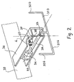
- FIG 1 there is shown a driver seat 1, a dashboard 2 and the control device of the trajectory 3 proposed by the invention.
- a central portion 30 connected to a shaft 33 (see Figure 2), the central portion 30 may contain an air bag as usual steering wheels.
- two branches 31G and 31D, extended by two handles 32G and 32D, are arranged at a distance from the rotary shaft 33 and preferably substantially symmetrical with respect thereto.
- the rotary shaft 33 is provided with at least one rotation angle sensor 34 and a return means 35 in the straight-line position.
- a box 36 belonging to the rigid structure 10 of the vehicle terminates in a base 37, the base forming bearings for an axle 38 rotatably mounted on the ends of the base 37.
- This axle 38 is also integral with the shaft.
- a link 4 equipped with a force sensor 40 extension / compression connects the sheath 39 to box 36.
- the driver's action is identical to what he would do with an existing passenger car today. It turns the handles 32G and 32D clockwise to turn right, and counterclockwise to turn left, as shown by the arrows F1 in Figure 1.
- the rotation is limited to a value much less than + 90 ° or -90 °.
- the rotation covers for example the range from -30 ° to + 30 °
- the handles 32G and 32D are essentially the first controller.
- the 32G and 32D handles are a strong action lever comparable to a traditional steering wheel where the driver prints an angle variation corresponding to a demand for variation of the yaw rate.
- the control device available to the driver comprises a second member for acting on the path of the vehicle, through which it can express a demand for transverse displacement constant cap.
- this second member comprises at least one force sensor arranged to detect a bias tending to weigh on said handles around a tilting axis substantially perpendicular to the rotary shaft, said tilting axis being preferably substantially within the plane of symmetry of the first member.
- the shaft 33 is arranged rather horizontally, ie as the steering column of the current passenger vehicles.
- this effort does not cause any displacement, but there is preferably a minimum threshold to be exceeded before modifying the trajectory. This effort is measured by the sensor 40.
- a minimum threshold to be exceeded before modifying the trajectory.
- This effort is measured by the sensor 40.
- the second member for acting on the path of the vehicle comprises at least one sensitive trigger, for example one on each handle, actuating one the transverse displacement constant cap in one direction and the other the transverse displacement constant cap in the other direction, depending on the amplitude of the pressure exerted on the trigger.
- the orientation of the shaft 33 is rather horizontal, contrary to what has been indicated above.
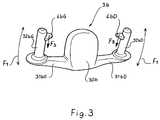
- FIG 3 we see an embodiment of a control of the trajectory 3b according to this second embodiment of the invention '.
- Several parts are very similar to what is found in the first embodiment, namely a central portion 30b, two branches 31bG and 31bD, extended by two handles 32bG and 32bD.
- a trigger 4bG and respectively 4bD disposed at a location chosen to be easily actuated voluntarily by the thumb, without the risk of being involuntarily actuated for example during a rotation of the control 3b.
- the action of the driver is identical to what was explained above.
- the driver acts on either of the triggers 4bG or 4bD.
- the trigger 4bG or 4bD For example, to move the vehicle transversely to the left, he squeezes the trigger 4bG, while to move the vehicle transversely to the right, he presses the trigger 4bD.
- This action on either of the triggers 4bG or 4bD can of course be combined with a rotation of the control 3b to combine a certain degree of transverse displacement and a course change request.
- the command printed by the driver (arrows F2 in FIG. 1 or action F3 on one of the keys 4bG or 4bD in FIG. 3) is translated in such a way that all the wheels of the vehicle turn in the same direction and at the same angle. More generally, in the case of a request for transverse translation without a request for a course change, whether or not the vehicle is making a change of course, the variation of the steering angle is identical on all the wheels of the vehicle. Therefore, the command printed by the driver (arrows F2 in FIG. 1 or action F3 on one of the keys 4bG or 4bD in FIG.
- both the rotation schematized by the arrows F1 as the control shown schematically by the arrows F2 or F3 are sent to a trajectory controller (not shown) loaded with adequate programs to to be able to drive the electric actuators at the steering wheels, preferably individually wheel by wheel.
- a trajectory controller (not shown) loaded with adequate programs to to be able to drive the electric actuators at the steering wheels, preferably individually wheel by wheel.
- the reduction between the rotation of the handles 32G and 32D (control according to the arrows F1) and the steering of the wheels is variable depending on the longitudinal movement speed of the vehicle, which the trajectory controller can easily take into account.
- the trajectory controller may superimpose any corrections determined by a trajectory control function such as that provided by an ESP system, and / or as that resulting from a dialogue with a means for controlling traffic outside the vehicle and / or a dialogue with a means of locating the GPS-type vehicle.
- the trajectory corrector determines the steering angle for each of the wheels accordingly.
- the steering angle of each wheel comprises a component resulting from the orders printed by the driver of the vehicle on his control means and a correction component.
- the pilot When traveling at a sustained speed, the pilot expresses requests for a change of trajectory with or without variation of the yaw rate, the two of course being able to be combined, for example, for an overtaking in a turn.
- the present invention makes it possible to offer control latitude of additional trajectories while maintaining the usual means of controlling the change of direction of the vehicle.
- the driver not used to this additional command may very well not use it and act only by printing rotations driving.
- an actuator for each steered wheel In an electrical system for acting on the path of a multiple steered wheel vehicle, preferably, there is an actuator for each steered wheel.
- a controller selectively imposes an appropriate steering angle for each of the steered wheels based at least on the location of said steered wheel on the vehicle, the vehicle speed and the requested course change.
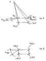
- Figure 4 illustrates the case of a yaw movement at a sustained speed.
- the location of the various steering wheels is indicated on the vehicle: left front steering wheel 1AvG, right front steering wheel 1AvD, left rear steering wheel 1ArG and right rear steering wheel 1ArD.
- left front steering wheel 1AvG right front steering wheel 1AvD
- left rear steering wheel 1ArG left rear steering wheel 1ArD
- right rear steering wheel 1ArD right rear steering wheel
- the trajectory controller controlling the steering angle selectively wheel by wheel can, from at least one signal delivered by the control device (for example a signal representative of the steering wheel angle imposed by the vehicle driver) and taking into account other relevant parameters (such as the longitudinal speed of movement of the vehicle), determine the spatial location of the instantaneous center of rotation ideal for the vehicle. This instantaneous center of rotation is identified by the point ⁇ .
- the trajectory controller calculates the steering angle of each of the wheels so that the plane of the wheel is substantially perpendicular to the line connecting the center of the wheel considered instantaneous center of rotation of the vehicle ⁇
- the trajectory controller is loaded with the appropriate programs to perform this calculation.
- Figure 5 illustrates the case of a change of trajectory by transverse displacement at constant heading. This time, we see that all the wheels point at the same angle ⁇ (T) .
- the invention also extends to an electric steering system for a vehicle of which only some wheels are steered. Compared to FIG. 4, the difference is of course that the angle ⁇ Ar is zero on the left and on the right. But this is only a particular case of the system explained above, in which the trajectory controller, steering the steering angle selectively wheel by wheel to the steering axle can, from the steering angle imposed by the driver of the vehicle and taking into account other relevant parameters such as the speed of longitudinal displacement of the vehicle, determining the spatial location of the instantaneous center of rotation ideal for the vehicle (point ⁇ ), this time necessarily located on the virtual line linking the center rear wheels.
- the invention proposes an electrical system for acting on the trajectory of a vehicle, all the steering wheels of which are controlled by an electric actuator of its own, the steering angle being imposed individually and selectively on each of the steering wheels. by its electric actuator, the system comprising a control member for acting on the trajectory of the vehicle, said control member being at the disposal of the driver, comprising a trajectory controller determining the spatial location of the instantaneous center of rotation of the vehicle as a function of at least one signal delivered by said organ of control and as a function of at least one signal representative of the effective trajectory of the vehicle, for example the longitudinal speed of the vehicle, and calculating the steering angle of each of the wheels so that the plane of the wheel is substantially perpendicular to the line connecting the center of the wheel considered instantaneous center of rotation of the vehicle ⁇ .
Abstract
Description
La présente invention se rapporte à la commande de changement de trajectoire d'un véhicule automobile.The present invention relates to the control of change of trajectory of a motor vehicle.
Dans l'état actuel de la technique, la commande de direction d'un véhicule automobile de tourisme se fait la plupart du temps au moyen d'un volant. Le conducteur agit par rotation sur le volant dans un sens ou dans l'autre pour orienter le véhicule dans une direction ou dans une autre. De cette façon, le conducteur confère un mouvement de lacet au véhicule. Par ailleurs, il se développe de plus en plus des moyens de commande électrique pour l'ensemble des actionneurs d'un véhicule automobile, et notamment la direction. Cette technologie est connue sous l'appellation anglo-saxonne « steer by wire ».In the current state of the art, the steering control of a passenger car is mostly done by means of a steering wheel. The driver rotates the steering wheel one way or the other to steer the vehicle in one direction or another. In this way, the driver gives a yawing motion to the vehicle. Furthermore, there is growing electric control means for all the actuators of a motor vehicle, including the steering. This technology is known by the Anglo-Saxon name "steer by wire".
La technologie de commande d'actionneurs par liaison électrique consiste à remplacer par des liaisons électriques les liaisons à l'heure actuelle en général hydrauliques ou mécaniques entre la commande et les actionneurs. Ainsi par exemple, en ce qui concerne la direction des véhicules automobiles, on va substituer au système mécanique, assisté ou non, existant entre le volant et les roues directrices, la chaîne suivante. La commande de direction à la disposition du conducteur du véhicule peut être un volant traditionnel ou une manette du genre manche à balais. Au niveau des roues, il existe un actionneur électrique, de préférence individuel roue par roue. Les ordres imprimés par le conducteur du véhicule sur son moyen de commande sont envoyés aux actionneurs par une liaison électrique, l'ensemble étant placé sous le contrôle d'un contrôleur de trajectoire chargé de programmes adéquats afin de pouvoir piloter les actionneurs de façon appropriée.The actuator control technology by electrical connection is to replace by electrical connections the current links usually hydraulic or mechanical between the control and the actuators. For example, as regards the direction of motor vehicles, we will replace the mechanical system, assisted or not, existing between the steering wheel and the steering wheels, the next chain. The steering control available to the driver of the vehicle may be a traditional steering wheel or a joystick like broomstick. At the wheels, there is an electric actuator, preferably individual wheel by wheel. The orders printed by the driver of the vehicle on his control means are sent to the actuators by an electrical connection, all being placed under the control of a trajectory controller loaded with adequate programs to be able to drive the actuators appropriately.
L'avantage de cette technologie est qu'elle se marie de façon idéale avec les progrès de l'électronique, qui permettent des asservissements de plus en plus sophistiqués et qui permettent de placer le braquage des roues non seulement sous le contrôle de la commande manuelle mais aussi sous le contrôle d'un système de sécurité. Ainsi par exemple, on peut imprimer aux roues directrices un angle qui tient non seulement compte de la commande du conducteur du véhicule, mais qui tient également compte de paramètres dynamiques observés sur le véhicule.The advantage of this technology is that it is ideally matched with the progress of the electronics, which allows more and more sophisticated servo-control and which makes it possible to place the steering of the wheels not only under the control of the manual control but also under the control of a security system. For example, it is possible to print on the steering wheels an angle which takes into account not only the driver's control of the vehicle, but which also takes into account dynamic parameters observed on the vehicle.
Lorsqu'un conducteur souhaite changer la trajectoire de son véhicule, cela peut répondre à deux besoins de nature assez différente. Le premier besoin est de prendre un virage et, dans ce cas, il est nécessaire d'imprimer une accélération de lacet au véhicule, suivie d'une phase où la vitesse de lacet varie peu, puis une décélération de lacet en sortie de virage, afin d'obtenir une direction de déplacement différente après la manoeuvre par rapport à ce qu'elle était avant la manoeuvre. Lorsqu'il s'agit de dépasser un véhicule sur une route ou une autoroute, on sait que le conducteur agit sur le volant pour imposer un léger virage à gauche pour les pays dans lesquels on circule à droite, puis immédiatement après un léger virage à droite lorsque le véhicule s'est déplacé transversalement de façon suffisante ; enfin, lorsque la manoeuvre de dépassement s'achève, à nouveau un léger virage pour de nouveau changer l'orientation du véhicule afin de se rapprocher de la bande de circulation initiale, et enfin un quatrième léger virage. On constate donc que, pour pouvoir effectuer une manoeuvre de dépassement, il est nécessaire d'imposer deux accélérations transversales au véhicule au moyen de quatre accélérations de lacets. Or en fait, seules les accélérations transversales sont utiles en manoeuvre de dépassement en ligne droite.When a driver wants to change the trajectory of his vehicle, it can meet two needs quite different in nature. The first need is to take a turn and, in this case, it is necessary to print a lace acceleration to the vehicle, followed by a phase where the yaw rate varies little, then a yaw rate deceleration at the end of the turn, in order to obtain a different direction of movement after the maneuver compared to what it was before the maneuver. When it comes to overtaking a vehicle on a road or highway, we know that the driver acts on the steering wheel to impose a slight left turn for the countries in which we drive on the right, then immediately after a slight turn to right when the vehicle has moved transversely enough; finally, when the overtaking maneuver is completed, again a slight turn to change the orientation of the vehicle again to get closer to the initial traffic band, and finally a fourth slight turn. It is therefore found that, to be able to perform an overtaking maneuver, it is necessary to impose two transverse accelerations to the vehicle by means of four laces accelerations. In fact, only transverse accelerations are useful in overtaking maneuver in a straight line.
La présente invention a donc pour objectif de proposer un système électrique pour agir sur la trajectoire d'un véhicule dont toutes les roues sont directrices, l'angle de braquage étant imposé individuellement et sélectivement sur chacune des roues directrices par un actionneur électrique dédié, ledit système électrique comportant un organe de commande pour agir sur la trajectoire du véhicule, ledit organe de commande étant à la disposition du conducteur, comportant un contrôleur de trajectoire déterminant pour chacune des roues directrices un angle de braquage de roue en fonction au moins d'un signal délivré par l'organe de commande de trajectoire du véhicule et en fonction d'au moins un signal représentatif de la trajectoire effective du véhicule. Le contrôleur de trajectoire est programmé de façon à assurer la cohérence entre la trajectoire désirée par le conducteur, par ses actions sur l'organe de commande, et la trajectoire effective telle qu'elle peut être observée par des capteurs adéquats (citons par exemple un capteur de vitesse longitudinale, un capteur d'accélération transversale, un capteur de lacet)..The present invention therefore aims to provide an electrical system for acting on the path of a vehicle of which all the wheels are steered, the steering angle being imposed individually and selectively on each of the steering wheels by a dedicated electric actuator, said electrical system comprising a control member for acting on the trajectory of the vehicle, said control member being at the disposal of the driver, comprising a trajectory controller determining for each of the steering wheels a wheel steering angle according to at least one signal delivered by the vehicle trajectory control member and as a function of at least one signal representative of the effective trajectory of the vehicle. The trajectory controller is programmed to ensure consistency between the trajectory desired by the driver, by its actions on the control member, and the effective trajectory as it can be observed by adequate sensors (for example a longitudinal speed sensor, a transverse acceleration sensor, a yaw sensor).
La présente invention a aussi pour objectif, indépendamment de l'objectif précédent, de mettre à la disposition du conducteur du véhicule une commande spécifique, permettant de provoquer une translation transversale du véhicule à cap constant, cette commande étant indépendante de la commande de changement de direction du véhicule, c'est à dire indépendante de la commande de lacet (changement de cap). Le brevet US 5,492,348 propose une commande de direction offrant quatre modes différents pour le braquage. La demande de brevet DE 44 04 594 propose un organe de commande de type joystick pouvant agir sur le braquage et sur le déplacement transversal séparément mais ce type de commande est très différent d'un volant.The present invention also aims, independently of the previous objective, to make available to the driver of the vehicle a specific command, to cause a transverse translation of the vehicle constant heading, this command being independent of the control of change of direction of the vehicle, ie independent of the yaw control (change of course). US Patent 5,492,348 proposes a steering control offering four different modes for steering. The patent application DE 44 04 594 proposes a joystick-type control device that can act on the steering and on the transverse displacement separately, but this type of control is very different from a steering wheel.
L'objectif poursuivi est de proposer une commande qui soit aussi peu déroutante que possible pour un conducteur déjà habitué à utiliser un volant pour agir sur la trajectoire de son véhicule, tout en apportant un potentiel de progrès.The objective is to offer a command that is as little confusing as possible for a driver already accustomed to using a steering wheel to act on the trajectory of his vehicle, while providing a potential for progress.
C'est pourquoi la présente invention conserve l'utilisation d'un premier organe du genre « volant » pour imprimer des changements de direction au véhicule. Pour rappel, un changement de direction correspond à un changement de cap. Les commandes de changement de direction du véhicule se font de façon conventionnelle, c'est-à-dire en imprimant une rotation à ce premier organe. Afin de découpler la commande de translation transversale du véhicule à cap constant de la commande de changement de direction du véhicule (changement de cap), la présente invention propose d'équiper le dispositif de commande d'un second organe spécifique pour imprimer au véhicule un déplacement transversal à cap constant (c'est à dire sans lacet).This is why the present invention retains the use of a first member of the "flying" type for printing direction changes to the vehicle. As a reminder, a change of direction corresponds to a change of course. The steering commands of the vehicle are done conventionally, that is to say by printing a rotation to this first body. In order to decouple the transverse translation control of the vehicle with constant heading of the vehicle direction change control (course change), the present invention proposes to equip the control device with a second specific member for printing the vehicle with a transversal displacement at constant heading (ie without lace).
Dès lors, l'invention porte également sur un dispositif de commande à la disposition du conducteur pour agir sur la trajectoire d'un véhicule dont toutes les roues sont directrices, par une double commande agissant séparément sur la mise en lacet et sur le déplacement transversal pur, la transmission des ordres de déplacement se faisant par voie électrique, le dispositif comprenant un premier organe de commande pour imprimer un mouvement de lacet au véhicule, le premier organe comportant essentiellement un arbre rotatif solidaire de deux poignées disposées à une certaine distance de l'arbre rotatif, ledit arbre rotatif étant pourvu d'au moins un capteur ... d'angle de rotation et d'un moyen de rappel en position ligne droite, et comportant un second organe pour imprimer au véhicule un déplacement transversal sans lacet.Therefore, the invention also relates to a control device available to the driver to act on the path of a vehicle with all the wheels are directed by a dual control acting separately on the yawning and the transverse displacement pure, the transmission of the displacement orders being done electrically, the device comprising a first control member for printing a yaw movement to the vehicle, the first member essentially comprising a rotary shaft integral with two handles disposed at a distance from the rotary shaft, said rotary shaft being provided with at least one sensor ... rotation angle and a return means in a straight line position, and having a second member for printing the vehicle a transverse displacement without lace.
L'invention est décrite plus en détail au moyen des figures suivantes, sur lesquels :
- ■ la figure 1 montre un dispositif de commande installé dans l'habitacle d'un véhicule ;
- ■ la figure 2 est un schéma montrant plus en détails l'agencement d'un mode de réalisation du dispositif de commande ;
- ■ la figure 3 montre une variante de réalisation d'un dispositif de commande installé dans l'habitacle d'un véhicule ;
- ■ la figure 4 est un schéma illustrant un changement de trajectoire avec mouvement de lacet ;
- ■ la figure 5 est un schéma illustrant un changement de trajectoire à cap constant.
- ■ Figure 1 shows a control device installed in the passenger compartment of a vehicle;
- Fig. 2 is a diagram showing in more detail the arrangement of an embodiment of the control device;
- ■ Figure 3 shows an alternative embodiment of a control device installed in the passenger compartment of a vehicle;
- FIG. 4 is a diagram illustrating a change of trajectory with yaw movement;
- FIG. 5 is a diagram illustrating a change in trajectory with constant heading.
A la figure 1, on voit un siège conducteur 1, un tableau de bord 2 et le dispositif de commande de la trajectoire 3 proposé par l'invention. On voit une partie centrale 30 reliée à un arbre 33 (voir figure 2), la partie centrale 30 pouvant contenir un sac gonflable comme les volants de direction usuels. De part et d'autre de cette partie centrale 30 et reliées à celle-ci, on voit deux branches 31G et 31D, prolongées par deux poignées 32G et 32D, disposées à une certaine distance de l'arbre rotatif 33 et de préférence de façon sensiblement symétrique par rapport à celui-ci.In Figure 1, there is shown a driver seat 1, a
A la figure 2, on voit que l'arbre rotatif 33 est pourvue d'au moins un capteur 34 d'angle de rotation et d'un moyen de rappel 35 en position ligne droite. Un caisson 36 appartenant à la structure rigide 10 du véhicule se termine par une embase 37, l'embase formant paliers pour un axe 38 monté rotatif sur les extrémités de l'embase 37. Cet axe 38 est par ailleurs solidaire de l'arbre d'un fourreau 39 à l'intérieur duquel est monté l'arbre rotatif 33, à rotation libre par rapport au fourreau 39. Enfin, une biellette 4 équipée d'un capteur 40 d'effort d'extension/compression relie le fourreau 39 au caisson 36.In FIG. 2, it can be seen that the
Pour prendre un virage, l'action du conducteur est identique à ce qu'il ferait avec un véhicule de tourisme existant de nos jours. Il fait tourner les poignées 32G et 32D dans le sens des aiguilles d'une montre pour tourner à droite, et dans le sens inverse des aiguilles d'une montre pour tourner à gauche, comme schématisé par les flèches F1 à la figure 1. La rotation possible est d'angle limité à une valeur très inférieure à +90° ou -90°. La rotation couvre par exemple la gamme allant de -30° à +30° Les poignées 32G et 32D constituent essentiellement le premier organe de commande. Les poignées 32G et 32D constituent un levier d'action fort comparable à un volant traditionnel auquel le conducteur imprime une variation d'angle correspondant à une demande de variation de la vitesse de lacet.To take a turn, the driver's action is identical to what he would do with an existing passenger car today. It turns the
Le dispositif de commande à la disposition du conducteur comporte un second organe permettant d'agir sur la trajectoire du véhicule, grâce auquel il peut exprimer une demande de déplacement transversal à cap constant.The control device available to the driver comprises a second member for acting on the path of the vehicle, through which it can express a demand for transverse displacement constant cap.
Dans une première variante de réalisation, ce second organe comporte au moins un capteur d'effort agencé pour détecter une sollicitation tendant à peser sur lesdites poignées autour d'un axe de basculement sensiblement perpendiculaire à l'arbre rotatif, ledit axe de basculement étant de préférence sensiblement compris dans le plan de symétrie du premier organe. Dans ce cas, l'arbre 33 est disposé plutôt horizontalement, c'est à dire comme la colonne de direction des véhicules de tourisme courants.In a first embodiment, this second member comprises at least one force sensor arranged to detect a bias tending to weigh on said handles around a tilting axis substantially perpendicular to the rotary shaft, said tilting axis being preferably substantially within the plane of symmetry of the first member. In this case, the
Le conducteur impose aux poignées 32G et 32D un effort de basculement comme schématisé par les flèches F2 à la figure 1, par exemple un effort tendant à éloigner la poignée 32G pour déplacer transversalement le véhicule vers la gauche tout en maintenant son orientation longitudinale inchangée, et un effort tendant à éloigner la poignée 32D pour déplacer transversalement le véhicule vers la droite tout en maintenant son orientation longitudinale inchangée. Selon une première possibilité, cet effort ne provoque aucun déplacement, mais il y a de préférence un seuil minimal à dépasser avant de modifier la trajectoire. Cet effort est mesuré par le capteur 40. Il y a d'autres possibilités de mise en oeuvre. On peut par exemple configurer la commande pour qu'il y ait un léger déplacement, notamment au delà d'un certain seuil pendant que la commande est active.The driver imposes on the
Dans une deuxième variante de réalisation, le second organe permettant d'agir sur la trajectoire du véhicule comporte au moins une gâchette sensitive, par exemple une sur chaque poignée, actionnant l'une le déplacement transversal à cap constant dans un sens et l'autre le déplacement transversal à cap constant dans l'autre sens, en fonction de l'amplitude de la pression exercée sur la gâchette. Dans cette variante, il n'y a pas de raison particulière dictant que l'orientation de l'arbre 33 soit plutôt horizontale, contrairement à ce qui a été indiqué ci-dessus.In a second alternative embodiment, the second member for acting on the path of the vehicle comprises at least one sensitive trigger, for example one on each handle, actuating one the transverse displacement constant cap in one direction and the other the transverse displacement constant cap in the other direction, depending on the amplitude of the pressure exerted on the trigger. In this variant, there is no particular reason dictating that the orientation of the
A la figure 3, on voit un exemple de réalisation d'une commande de la trajectoire 3b conforme à cette deuxième variante de réalisation de l'invention'. Plusieurs parties sont très similaires à ce que l'on trouve dans la première variante de réalisation, à savoir une partie centrale 30b, deux branches 31bG et 31bD, prolongées par deux poignées 32bG et 32bD. Sur chacune des poignées 32bG et 32bD, on voit une gâchette 4bG et respectivement 4bD disposées à un emplacement choisi pour être facilement actionnable volontairement par le pouce, sans risquer d'être actionnée involontairement par exemple lors d'une rotation de la commande 3b.In Figure 3, we see an embodiment of a control of the
Pour prendre un virage, l'action du conducteur est identique à ce qui a été expliqué ci-dessus. Pour obtenir un déplacement transversal à cap constant, le conducteur agit sur l'une ou l'autre des gâchettes 4bG ou 4bD. Par exemple, pour déplacer transversalement le véhicule vers la gauche, il appuie sur la gâchette 4bG, alors que pour déplacer transversalement le véhicule vers la droite, il appuie sur la gâchette 4bD. Cette action sur l'une ou l'autre des gâchettes 4bG ou 4bD peut bien entendu être combinée avec une rotation de la commande 3b pour combiner un certain degré de déplacement transversal et une demande de changement de cap.To take a turn, the action of the driver is identical to what was explained above. To obtain a transverse displacement at constant heading, the driver acts on either of the triggers 4bG or 4bD. For example, to move the vehicle transversely to the left, he squeezes the trigger 4bG, while to move the vehicle transversely to the right, he presses the trigger 4bD. This action on either of the triggers 4bG or 4bD can of course be combined with a rotation of the
Dans le cas d'une translation transversale à cap constant, la commande imprimé par le conducteur (flèches F2 à la figure 1 ou action F3 sur l'une des touches 4bG ou 4bD à la figure 3) est traduite de façon à ce que toutes les roues du véhicule braquent dans la même direction et du même angle. Plus généralement, en cas de demande de translation transversale sans demande de changement de cap, que le véhicule soit en train d'opérer un changement de cap ou non, la variation d'angle de braquage est identique sur toutes les roues du véhicule. Dès lors, la commande imprimé par le conducteur (flèches F2 à la figure 1 ou action F3 sur l'une des touches 4bG ou 4bD à la figure 3) est traduite de façon à ce que toutes les roues du véhicule braquent dans la même direction et du même angle (ou, plus généralement, de façon à ce que la variation d'angle de braquage soit identique sur toutes les roues). De cette façon, on évite d'imposer au véhicule des accélérations de lacet inutiles pour la manoeuvre et d'autant plus préjudiciables que l'inertie de lacet du véhicule est importante. Il en résulte une réduction de l'usure des pneus. Un véhicule ainsi équipé passe bien plus facilement le test dit « de l'élan ». C'est l'avantage apporté par la double commande agissant séparément sur la mise en lacet et sur le déplacement transversal pur.In the case of a transversal translation with a constant heading, the command printed by the driver (arrows F2 in FIG. 1 or action F3 on one of the keys 4bG or 4bD in FIG. 3) is translated in such a way that all the wheels of the vehicle turn in the same direction and at the same angle. More generally, in the case of a request for transverse translation without a request for a course change, whether or not the vehicle is making a change of course, the variation of the steering angle is identical on all the wheels of the vehicle. Therefore, the command printed by the driver (arrows F2 in FIG. 1 or action F3 on one of the keys 4bG or 4bD in FIG. 3) is translated so that all the wheels of the vehicle turn in the same direction and the same angle (or, more generally, so that the variation of steering angle is the same on all wheels). In this way, it avoids imposing the vehicle yaw accelerations unnecessary for the maneuver and all the more detrimental that the inertia yaw of the vehicle is important. This results in a reduction of tire wear. A vehicle thus equipped passes much more easily the test said "momentum". This is the advantage provided by the dual control acting separately on the lace and on the pure transverse displacement.
Les ordres imprimés par le conducteur du véhicule sur son moyen de commande, aussi bien la rotation schématisée par les flèches F1 que la commande schématisé par les flèches F2 ou F3, sont envoyés à un contrôleur de trajectoire (non représenté) chargé de programmes adéquats afin de pouvoir piloter les actionneurs électriques au niveau des roues directrices, de préférence individuellement roue par roue. De préférence, la démultiplication entre la rotation des poignées 32G et 32D (commande selon les flèches F1) et le braquage des roues est variable en fonction de la vitesse de déplacement longitudinale du véhicule, ce que le contrôleur de trajectoire peut aisément prendre en compte.The orders printed by the driver of the vehicle on his control means, both the rotation schematized by the arrows F1 as the control shown schematically by the arrows F2 or F3, are sent to a trajectory controller (not shown) loaded with adequate programs to to be able to drive the electric actuators at the steering wheels, preferably individually wheel by wheel. Preferably, the reduction between the rotation of the
Bien entendu, afin de pouvoir effectuer un déplacement transversal sans lacet, c'est à dire sans changement de cap (commande schématisée par les flèches F2 ou F3), il convient que toutes les roues du véhicule soient directrices, afin de pouvoir les braquer toutes du même angle, aux dérives des pneus près. A titre purement illustratif, soulignons que la technologie décrite dans la demande de brevet EP 0 878 332 et la demande de brevet EP 0 878 378 se prête aisément à construire un véhicule dont toutes les roues sont directrices. Plus généralement, afin de pouvoir mettre en oeuvre l'invention, le pré-requis est d'installer au moins un actionneur pour braquer les roues sur chaque essieu. Chaque essieu peut comporter une liaison mécanique entre roues directrices, du genre crémaillère de direction, et le coulissement de celle-ci est contrôlé par un seul actionneur électrique.Of course, in order to be able to make a transverse displacement without lace, that is to say without change of course (command shown schematically by the arrows F2 or F3), it is appropriate that all the wheels of the vehicle are directional, in order to be able to point them all of same angle, with the drifts of the tires close. As a purely illustrative example, it should be emphasized that the technology described in patent application EP 0 878 332 and patent application EP 0 878 378 is easy to construct a vehicle with all the wheels being steered. More generally, in order to implement the invention, the prerequisite is to install at least one actuator to steer the wheels on each axle. Each axle may comprise a mechanical connection between the steering wheels, of the rack and pinion type, and the sliding thereof is controlled by a single electric actuator.
Dans une mise en oeuvre plus sophistiquée de la présente invention, on peut aussi installer un actionneur électrique sur chaque roue pour commander l'angle de braquage individuellement sur chaque roue, la cohérence des braquages individuels en fonction de la trajectoire souhaitée pour le véhicule étant alors assurée par ledit contrôleur de trajectoire.In a more sophisticated implementation of the present invention, it is also possible to install an electric actuator on each wheel to control the steering angle individually on each wheel, the coherence of the individual deflections according to the desired trajectory for the vehicle then being provided by said trajectory controller.
Bien entendu, aux ordres imprimés par le conducteur du véhicule sur son moyen de commande, le contrôleur de trajectoire peut superposer des éventuels correctifs déterminés par une fonction de contrôle de la trajectoire comme celle procurée par un système ESP, et/ou comme celle résultant d'un dialogue avec un moyen de contrôle de trafic extérieur au véhicule et/ou un dialogue avec un moyen de localisation du véhicule de type GPS. Le correcteur de trajectoire détermine l'angle de braquage pour chacune des roues en conséquence. Dans ces cas, l'angle de braquage de chaque roue comporte une composante résultant des ordres imprimés par le conducteur du véhicule sur son moyen de commande et une composante de correction.Of course, to the orders printed by the driver of the vehicle on his control means, the trajectory controller may superimpose any corrections determined by a trajectory control function such as that provided by an ESP system, and / or as that resulting from a dialogue with a means for controlling traffic outside the vehicle and / or a dialogue with a means of locating the GPS-type vehicle. The trajectory corrector determines the steering angle for each of the wheels accordingly. In these cases, the steering angle of each wheel comprises a component resulting from the orders printed by the driver of the vehicle on his control means and a correction component.
En déplacement à vitesse soutenue, le pilote exprime des demandes de changement de trajectoire avec ou sans variation de la vitesse de lacet, les deux pouvant bien entendu être combinés par exemple pour un dépassement dans un virage.When traveling at a sustained speed, the pilot expresses requests for a change of trajectory with or without variation of the yaw rate, the two of course being able to be combined, for example, for an overtaking in a turn.
Il est important de pouvoir tenir compte de l'éducation des conducteurs de véhicules automobiles. La présente invention permet d'offrir une latitude de commande des trajectoires supplémentaire tout en maintenant le moyen usuel de commander le changement de direction du véhicule. Ainsi, le conducteur non habitué à cette commande supplémentaire pourra très bien ne pas s'en servir et agir seulement en imprimant des rotations au volant. De plus, on peut s'habituer progressivement à cette commande supplémentaire.It is important to consider the education of motor vehicle drivers. The present invention makes it possible to offer control latitude of additional trajectories while maintaining the usual means of controlling the change of direction of the vehicle. Thus, the driver not used to this additional command may very well not use it and act only by printing rotations driving. In addition, you can gradually get used to this additional command.
Dans un système électrique pour agir sur la trajectoire d'un véhicule à roues directrices multiples, de préférence, il y a un actionneur pour chaque roue directrice. Un contrôleur permet d'imposer sélectivement un angle de braquage approprié à chacune des roues directrices en fonction au moins de la localisation de ladite roue directrice sur le véhicule, de la vitesse du véhicule et du changement de trajectoire demandé.In an electrical system for acting on the path of a multiple steered wheel vehicle, preferably, there is an actuator for each steered wheel. A controller selectively imposes an appropriate steering angle for each of the steered wheels based at least on the location of said steered wheel on the vehicle, the vehicle speed and the requested course change.
La figure 4 illustre le cas d'un mouvement de lacet à une vitesse soutenue. On repère sur le véhicule la localisation des diverses roues directrices : roue directrice avant gauche 1AvG, roue directrice avant droite 1AvD, roue directrice arrière gauche 1ArG et roue directrice arrière droite 1ArD. On sait que pour maintenir une bonne stabilité du véhicule, il est utile de faire braquer les roues arrière dans le même sens que les roues avant, mais d'un angle αArG(L) plus faible que l'angle αAvG(L) à l'avant. De façon générale, le contrôleur de trajectoire, pilotant l'angle de braquage sélectivement roue par roue peut, à partir d'au moins un signal délivré par le dispositif de commande (par exemple un signal représentatif de l'angle au volant imposé par le conducteur du véhicule) et tenant compte d'autres paramètres pertinents (comme la vitesse de déplacement longitudinal du véhicule), déterminer la localisation spatiale du centre instantané de rotation idéal pour le véhicule. Ce centre instantané de rotation est identifié par le point Ω. Sur cette base, le contrôleur de trajectoire calcule l'angle de braquage de chacune des roues de façon à ce que le plan de la roue se présente sensiblement perpendiculairement à la ligne reliant le centre de la roue considérée au centre instantané de rotation du véhicule Ω : en reliant le centre instantané de rotation au centre de chacune des roues directrices, on peut calculer l'angle de braquage de chacune des roues de façon à ce que le plan de la roue se présente sensiblement perpendiculairement à la ligne reliant le centre de la roue considérée au centre instantané de rotation du véhicule Ω. Le contrôleur de trajectoire est chargé des programmes adéquats pour effectuer ce calcul. A la dérive des pneus près, le véhicule tourne autour du centre instantané de rotation du véhicule Ω. Le centre instantané de rotation du véhicule Ω est en permanence calculée de façon dynamique, en fonction des conditions de conduite (vitesse du véhicule, vitesse de lacet, ...).Figure 4 illustrates the case of a yaw movement at a sustained speed. The location of the various steering wheels is indicated on the vehicle: left front steering wheel 1AvG, right front steering wheel 1AvD, left rear steering wheel 1ArG and right rear steering wheel 1ArD. It is known that in order to maintain a good stability of the vehicle, it is useful to have the rear wheels steer in the same direction as the front wheels, but with an angle α ArG (L) smaller than the angle α AvG (L) in the front. In general, the trajectory controller, controlling the steering angle selectively wheel by wheel can, from at least one signal delivered by the control device (for example a signal representative of the steering wheel angle imposed by the vehicle driver) and taking into account other relevant parameters (such as the longitudinal speed of movement of the vehicle), determine the spatial location of the instantaneous center of rotation ideal for the vehicle. This instantaneous center of rotation is identified by the point Ω. On this basis, the trajectory controller calculates the steering angle of each of the wheels so that the plane of the wheel is substantially perpendicular to the line connecting the center of the wheel considered instantaneous center of rotation of the vehicle Ω By connecting the instantaneous center of rotation to the center of each of the steered wheels, it is possible to calculate the steering angle of each of the wheels so that the plane of the wheel is substantially perpendicular to the line connecting the center of the wheel. wheel considered instant center of rotation of the vehicle Ω. The trajectory controller is loaded with the appropriate programs to perform this calculation. When the tires drift by, the vehicle turns around the instantaneous center of rotation of the vehicle Ω. The instantaneous center of rotation of the vehicle Ω is continuously calculated dynamically, according to the driving conditions (vehicle speed, yaw rate, ...).
Enfin, la figure 5 illustre le cas d'un changement de trajectoire par déplacement transversal à cap constant. On voit cette fois que toutes les roues braquent du même angle α(T).Finally, Figure 5 illustrates the case of a change of trajectory by transverse displacement at constant heading. This time, we see that all the wheels point at the same angle α (T) .
Enfin, l'invention s'étend aussi à un système de direction électrique pour véhicule dont certaines roues seulement sont directrices. Par rapport à la figure 4, la différence est bien entendu que l'angle αAr est nul à gauche et à droite. Mais ceci ne constitue qu'un cas particulier du système expliqué ci-dessus, dans lequel le contrôleur de trajectoire, pilotant l'angle de braquage sélectivement roue par roue à l'essieu directeur peut, à partir de l'angle au volant imposé par le conducteur du véhicule et tenant compte d'autres paramètres pertinents comme la vitesse de déplacement longitudinal du véhicule, déterminer la localisation spatiale du centre instantané de rotation idéal pour le véhicule (point Ω), cette fois nécessairement localisé sur la droite virtuelle liant le centre des roues arrières. De même, à partir du moment où ce centre instantané de rotation est choisi, en le reliant au centre de chacune des roues directrices, on peut calculer l'angle de braquage de chacune des roues de façon à ce que le plan de la roue se présente sensiblement perpendiculairement à la ligne reliant le centre de la roue considérée au centre instantané de rotation du véhicule Ω. Le contrôleur de trajectoire est chargé des programmes adéquats pour effectuer ce calcul, en permanence, de façon dynamique. A la dérive des pneus près, le véhicule tourne autour du centre instantané de rotation du véhicule Ω.Finally, the invention also extends to an electric steering system for a vehicle of which only some wheels are steered. Compared to FIG. 4, the difference is of course that the angle α Ar is zero on the left and on the right. But this is only a particular case of the system explained above, in which the trajectory controller, steering the steering angle selectively wheel by wheel to the steering axle can, from the steering angle imposed by the driver of the vehicle and taking into account other relevant parameters such as the speed of longitudinal displacement of the vehicle, determining the spatial location of the instantaneous center of rotation ideal for the vehicle (point Ω), this time necessarily located on the virtual line linking the center rear wheels. Similarly, from the moment when this instantaneous center of rotation is chosen, by connecting it to the center of each of the steering wheels, it is possible to calculate the steering angle of each of the wheels so that the plane of the wheel is is substantially perpendicular to the line connecting the center of the wheel considered instantaneous center of rotation of the vehicle Ω. The trajectory controller is responsible for the appropriate programs to perform this calculation, permanently, dynamically. When the tires drift by, the vehicle turns around the instantaneous center of rotation of the vehicle Ω.
Dès lors, l'invention propose un système électrique pour agir sur la trajectoire d'un véhicule dont toutes les roues directrices sont commandées par un actionneur électrique qui lui est propre, l'angle de braquage étant imposé individuellement et sélectivement sur chacune des roues directrices par son actionneur électrique, le système comportant un organe de commande pour agir sur la trajectoire du véhicule, ledit organe de commande étant à la disposition du conducteur, comportant un contrôleur de trajectoire déterminant la localisation spatiale du centre instantané de rotation du véhicule en fonction d'au moins un signal délivré par ledit organe de commande et en fonction d'au moins un signal représentatif de la trajectoire effective du véhicule, par exemple la vitesse longitudinale du véhicule, et calculant l'angle de braquage de chacune des roues de façon à ce que le plan de la roue se présente sensiblement perpendiculairement à la ligne reliant le centre de la roue considérée au centre instantané de rotation du véhicule Ω.Therefore, the invention proposes an electrical system for acting on the trajectory of a vehicle, all the steering wheels of which are controlled by an electric actuator of its own, the steering angle being imposed individually and selectively on each of the steering wheels. by its electric actuator, the system comprising a control member for acting on the trajectory of the vehicle, said control member being at the disposal of the driver, comprising a trajectory controller determining the spatial location of the instantaneous center of rotation of the vehicle as a function of at least one signal delivered by said organ of control and as a function of at least one signal representative of the effective trajectory of the vehicle, for example the longitudinal speed of the vehicle, and calculating the steering angle of each of the wheels so that the plane of the wheel is substantially perpendicular to the line connecting the center of the wheel considered instantaneous center of rotation of the vehicle Ω.
Claims (4)
- Control device available to the driver for altering the direction of a vehicle, all of the wheels of which are steered wheels, by a dual control acting separately on the yawing and on the pure transverse displacement, the displacement instructions being transmitted by electrical means, the device comprising a first control component for applying a yaw movement to the vehicle, the first component essentially comprising a rotary shaft (33) integral with two handles (32G, 32D), which are arranged at a certain distance from the rotary shaft, the said rotary shaft being provided with at least one angle-of-rotation sensor (34) and with a means (35) for returning to a straight-line position, and comprising a second component for applying a yaw-free transverse displacement to the vehicle.
- Device according to Claim 1, in which the second component comprises at least one force sensor (40) which is designed to detect an action tending to tilt the said handles about a tilting axis perpendicular to the rotary shaft.
- Device according to Claim 1, in which the second component essentially comprises a sensitive trigger on each handle, one actuating the transverse displacement in one direction and the other actuating the transverse displacement in the other direction.
- Device according to Claim 1, in which the first component is at least partially in the form of a steering wheel.
Applications Claiming Priority (4)
| Application Number | Priority Date | Filing Date | Title |
|---|---|---|---|
| FR0115222 | 2001-11-23 | ||
| FR0115222A FR2832682A1 (en) | 2001-11-23 | 2001-11-23 | Steering control for vehicle uses electrical linkage, with angle and force sensors detecting movement of two-handled steering wheel |
| FR0205662A FR2839291A1 (en) | 2002-05-03 | 2002-05-03 | Steering control for vehicle uses electrical linkage, with angle and force sensors detecting movement of two-handled steering wheel |
| FR0205662 | 2002-05-03 |
Publications (3)
| Publication Number | Publication Date |
|---|---|
| EP1316490A2 EP1316490A2 (en) | 2003-06-04 |
| EP1316490A3 EP1316490A3 (en) | 2003-10-08 |
| EP1316490B1 true EP1316490B1 (en) | 2006-03-15 |
Family
ID=26213277
Family Applications (1)
| Application Number | Title | Priority Date | Filing Date |
|---|---|---|---|
| EP02025477A Expired - Lifetime EP1316490B1 (en) | 2001-11-23 | 2002-11-15 | Electric steering for vehicles |
Country Status (5)
| Country | Link |
|---|---|
| EP (1) | EP1316490B1 (en) |
| JP (1) | JP4026131B2 (en) |
| CN (1) | CN1281450C (en) |
| AT (1) | ATE320367T1 (en) |
| DE (1) | DE60209847T2 (en) |
Families Citing this family (17)
| Publication number | Priority date | Publication date | Assignee | Title |
|---|---|---|---|---|
| NL1015626C2 (en) * | 2000-05-18 | 2001-11-20 | Skf Eng & Res Centre Bv | Steering gear for an electrically controlled (drive-by-wire) vehicle. |
| DE102004063916A1 (en) * | 2004-01-21 | 2005-11-10 | TÜV Automotive GmbH TÜV SÜD Gruppe | Multi-lane vehicle for performing crash tests |
| DE102004055282A1 (en) * | 2004-11-16 | 2006-06-01 | Mobil Elektronik Gmbh | Steering system for vehicle |
| JP4581660B2 (en) * | 2004-12-02 | 2010-11-17 | 日産自動車株式会社 | Vehicle steering system |
| JP4574407B2 (en) * | 2005-03-24 | 2010-11-04 | 本田技研工業株式会社 | Steering device |
| JP4528213B2 (en) * | 2005-06-23 | 2010-08-18 | 本田技研工業株式会社 | Vehicle steering system |
| FR2887839B1 (en) * | 2005-07-04 | 2007-09-14 | Conception & Dev Michelin Sa | STEERING SYSTEM OF A VEHICLE COMPRISING A DEGRADED OPERATING MODE IN THE EVENT OF A FAULT IN A WHEEL ROTATING ACTUATOR. |
| DE102005038855A1 (en) * | 2005-08-12 | 2007-02-15 | Takata-Petri Ag | steering wheel assembly |
| US7631714B2 (en) * | 2006-06-27 | 2009-12-15 | Gordon Ewbank Dower | Motor vehicle steering control |
| FR2928130B1 (en) * | 2008-02-29 | 2010-05-28 | Moulene | MOTORIZED VEHICLE WITH CONTROLLED INCLINATION. |
| CN102781764B (en) * | 2010-02-25 | 2014-12-17 | 丰田自动车株式会社 | Steering control device |
| JP4980445B2 (en) * | 2010-05-17 | 2012-07-18 | 本田技研工業株式会社 | Steering device |
| DE102011054947B4 (en) | 2011-10-31 | 2018-08-16 | Deutsches Zentrum für Luft- und Raumfahrt e.V. | Control device for vehicle control |
| DE102011118133A1 (en) * | 2011-11-10 | 2013-05-16 | Leopold Kostal Gmbh & Co. Kg | Steering device for a motor vehicle |
| CN105753801B (en) * | 2016-03-25 | 2018-06-01 | 浙江工业大学 | A kind of preparation method of s-triazine compound |
| DE102016115466B4 (en) | 2016-08-19 | 2021-02-11 | Thyssenkrupp Ag | Control horn for steering a motor vehicle |
| CN106218703B (en) * | 2016-09-12 | 2018-11-06 | 北京汽车股份有限公司 | Learner-driven vehicle, steering system of instruction car and its control method |
Citations (6)
| Publication number | Priority date | Publication date | Assignee | Title |
|---|---|---|---|---|
| US2203810A (en) * | 1939-06-26 | 1940-06-11 | Berry Wilbert Paul | Steering system for automobiles |
| US3198541A (en) * | 1962-06-18 | 1965-08-03 | Clark Equipment Co | Universal steering apparatus |
| DE3124181A1 (en) * | 1981-06-19 | 1983-01-05 | Thassilo Dr Med Schmidt | Steering device for steering shafts for vehicles, in particular motor vehicles |
| US5348111A (en) * | 1989-06-08 | 1994-09-20 | Group Lotus Plc | Wheeled vehicle steering system |
| DE4404594A1 (en) * | 1994-02-12 | 1995-08-17 | Dieter Wittelsberger | Vehicle combined steering, acceleration and braking control unit |
| US5492348A (en) * | 1992-09-29 | 1996-02-20 | Shaw; David C. | Vehicle steering system |
Family Cites Families (4)
| Publication number | Priority date | Publication date | Assignee | Title |
|---|---|---|---|---|
| AUPM545594A0 (en) * | 1994-05-06 | 1994-05-26 | Spark, Ian James | Improved agricultural implement |
| FR2763284A1 (en) | 1997-05-16 | 1998-11-20 | Conception & Dev Michelin Sa | PACKAGE INCLUDING A WHEEL AND INTEGRATED WHEEL SUSPENSION |
| FR2763300A1 (en) | 1997-05-16 | 1998-11-20 | Conception & Dev Michelin Sa | VEHICLE HAVING A SUSPENSION HAVING AN ACTIVE BODY VARIATION |
| DE20117198U1 (en) * | 2000-03-20 | 2002-03-14 | Hubtex Maschb Gmbh & Co Kg | Reusable transport vehicle, in particular reusable forklift |
-
2002
- 2002-11-15 AT AT02025477T patent/ATE320367T1/en not_active IP Right Cessation
- 2002-11-15 DE DE60209847T patent/DE60209847T2/en not_active Expired - Lifetime
- 2002-11-15 EP EP02025477A patent/EP1316490B1/en not_active Expired - Lifetime
- 2002-11-22 CN CN02148895.9A patent/CN1281450C/en not_active Expired - Fee Related
- 2002-11-25 JP JP2002340228A patent/JP4026131B2/en not_active Expired - Fee Related
Patent Citations (6)
| Publication number | Priority date | Publication date | Assignee | Title |
|---|---|---|---|---|
| US2203810A (en) * | 1939-06-26 | 1940-06-11 | Berry Wilbert Paul | Steering system for automobiles |
| US3198541A (en) * | 1962-06-18 | 1965-08-03 | Clark Equipment Co | Universal steering apparatus |
| DE3124181A1 (en) * | 1981-06-19 | 1983-01-05 | Thassilo Dr Med Schmidt | Steering device for steering shafts for vehicles, in particular motor vehicles |
| US5348111A (en) * | 1989-06-08 | 1994-09-20 | Group Lotus Plc | Wheeled vehicle steering system |
| US5492348A (en) * | 1992-09-29 | 1996-02-20 | Shaw; David C. | Vehicle steering system |
| DE4404594A1 (en) * | 1994-02-12 | 1995-08-17 | Dieter Wittelsberger | Vehicle combined steering, acceleration and braking control unit |
Also Published As
| Publication number | Publication date |
|---|---|
| JP2003165445A (en) | 2003-06-10 |
| CN1281450C (en) | 2006-10-25 |
| JP4026131B2 (en) | 2007-12-26 |
| CN1422776A (en) | 2003-06-11 |
| ATE320367T1 (en) | 2006-04-15 |
| DE60209847D1 (en) | 2006-05-11 |
| DE60209847T2 (en) | 2006-10-12 |
| EP1316490A3 (en) | 2003-10-08 |
| EP1316490A2 (en) | 2003-06-04 |
Similar Documents
| Publication | Publication Date | Title |
|---|---|---|
| EP1316490B1 (en) | Electric steering for vehicles | |
| EP1883569B1 (en) | Vehicle steering control system comprising no mechanical linkage between the steering wheel and the steered wheels | |
| EP1428740B1 (en) | Vehicle steering system with an emergency operating mode in the event of a failure of a wheel steering actuator | |
| EP1899212B1 (en) | Vehicle steering control system comprising no mechanical linkage between the steering wheel and the steered wheels | |
| EP3325327B1 (en) | Steering arrangement for tiltable vehicle | |
| FR2832682A1 (en) | Steering control for vehicle uses electrical linkage, with angle and force sensors detecting movement of two-handled steering wheel | |
| FR2804648A1 (en) | STEERING DEVICE FOR VEHICLE | |
| FR2495088A1 (en) | STEERING SYSTEM FOR FOUR-WHEELED VEHICLES HAVING REAR WHEEL CONTROL IN ACCORDANCE WITH VEHICLE MOVEMENT | |
| FR2750389A1 (en) | CONTROL ELEMENT DEVICE FOR CONTROLLING THE LONGITUDINAL MOVEMENT AND THE TRANSVERSAL MOVEMENT OF A MOTOR VEHICLE | |
| FR2903658A1 (en) | FLY CONTROL AND FLY CONTROL SYSTEM FOR AIRCRAFT. | |
| FR2557058A1 (en) | STEERING SYSTEM FOR AUTOMOTIVE FOUR-WHEEL DRIVING VEHICLES HAVING A DEVICE FOR SERVICING THE FRONT AND REAR WHEEL BEAM ANGLES | |
| JP4921990B2 (en) | Vehicle yaw moment control device | |
| JP6898428B2 (en) | vehicle | |
| JP2006521959A (en) | Vehicle having vehicle dynamic performance selection switch on steering wheel | |
| FR2809369A1 (en) | STEERING DEVICE FOR MOTOR VEHICLE | |
| JP4258598B2 (en) | Driving device | |
| WO2016107991A1 (en) | Ground vehicle with front and rear wheel drive, and method for steering the front and rear wheels of said vehicle | |
| CA3065871C (en) | Control device for undercarriage motorization | |
| FR2839291A1 (en) | Steering control for vehicle uses electrical linkage, with angle and force sensors detecting movement of two-handled steering wheel | |
| FR2903659A1 (en) | Aircraft flight and brake control system i.e. stick controller, has sensors generating steering control, from movement of handle, acting on aerodynamic surfaces, and spring associated to brake lever to act on brake system of landing gear | |
| FR2907090A1 (en) | DEVICE FOR CORRECTING THE TRACK OF A MOTOR VEHICLE COMPRISING THE FIRST SELECTIVE BRAKING MEANS OF THE WHEELS AND THE SECOND MEANS OF PIVOTING THE REAR WHEELS | |
| WO2020070428A1 (en) | Method of determining a setpoint torque on the basis of a reversibility function calculating a target speed for a steering wheel depending on a steering wheel angle and a yaw rate | |
| FR2972168A1 (en) | Decoupled steering control system i.e. steer-by-wire type control system, for controlling steering of wheels in e.g. front axle in car, has determination unit determining average maximum steering angle to be applied on wheels | |
| EP0352185B1 (en) | Front and rear steering device for an automotive vehicle with four steered wheels | |
| FR2943308A1 (en) | Terrestrial three-wheeled vehicle i.e. electrical assistance bicycle type tricycle, has mechanical adjustment unit including deformable quadrilaterals, guides, slides and driving cable to adjust ratio of inclination angle and steering angle |
Legal Events
| Date | Code | Title | Description |
|---|---|---|---|
| PUAI | Public reference made under article 153(3) epc to a published international application that has entered the european phase |
Free format text: ORIGINAL CODE: 0009012 |
|
| AK | Designated contracting states |
Designated state(s): AT BE BG CH CY CZ DE DK EE ES FI FR GB GR IE IT LI LU MC NL PT SE SK TR |
|
| AX | Request for extension of the european patent |
Extension state: AL LT LV MK RO SI |
|
| PUAL | Search report despatched |
Free format text: ORIGINAL CODE: 0009013 |
|
| RIC1 | Information provided on ipc code assigned before grant |
Ipc: 7B 62D 7/15 B Ipc: 7B 62D 1/22 B Ipc: 7B 62D 1/00 A Ipc: 7B 62D 1/04 B Ipc: 7B 62D 5/00 B |
|
| AK | Designated contracting states |
Kind code of ref document: A3 Designated state(s): AT BE BG CH CY CZ DE DK EE ES FI FR GB GR IE IT LI LU MC NL PT SE SK TR |
|
| AX | Request for extension of the european patent |
Extension state: AL LT LV MK RO SI |
|
| 17P | Request for examination filed |
Effective date: 20040408 |
|
| AKX | Designation fees paid |
Designated state(s): AT BE BG CH CY CZ DE DK EE ES FI FR GB GR IE IT LI LU MC NL PT SE SK TR |
|
| 17Q | First examination report despatched |
Effective date: 20041217 |
|
| GRAP | Despatch of communication of intention to grant a patent |
Free format text: ORIGINAL CODE: EPIDOSNIGR1 |
|
| GRAS | Grant fee paid |
Free format text: ORIGINAL CODE: EPIDOSNIGR3 |
|
| GRAA | (expected) grant |
Free format text: ORIGINAL CODE: 0009210 |
|
| AK | Designated contracting states |
Kind code of ref document: B1 Designated state(s): AT BE BG CH CY CZ DE DK EE ES FI FR GB GR IE IT LI LU MC NL PT SE SK TR |
|
| PG25 | Lapsed in a contracting state [announced via postgrant information from national office to epo] |
Ref country code: IT Free format text: LAPSE BECAUSE OF FAILURE TO SUBMIT A TRANSLATION OF THE DESCRIPTION OR TO PAY THE FEE WITHIN THE PRE;WARNING: LAPSES OF ITALIAN PATENTS WITH EFFECTIVE DATE BEFORE 2007 MAY HAVE OCCURRED AT ANY TIME BEFORE 2007. THE CORRECT EFFECTIVE DATE MAY BE DIFFERENT FROM THE ONE RECORDED.SCRIBED TIME-LIMIT Effective date: 20060315 Ref country code: AT Free format text: LAPSE BECAUSE OF FAILURE TO SUBMIT A TRANSLATION OF THE DESCRIPTION OR TO PAY THE FEE WITHIN THE PRESCRIBED TIME-LIMIT Effective date: 20060315 Ref country code: SK Free format text: LAPSE BECAUSE OF FAILURE TO SUBMIT A TRANSLATION OF THE DESCRIPTION OR TO PAY THE FEE WITHIN THE PRESCRIBED TIME-LIMIT Effective date: 20060315 Ref country code: NL Free format text: LAPSE BECAUSE OF FAILURE TO SUBMIT A TRANSLATION OF THE DESCRIPTION OR TO PAY THE FEE WITHIN THE PRESCRIBED TIME-LIMIT Effective date: 20060315 Ref country code: FI Free format text: LAPSE BECAUSE OF FAILURE TO SUBMIT A TRANSLATION OF THE DESCRIPTION OR TO PAY THE FEE WITHIN THE PRESCRIBED TIME-LIMIT Effective date: 20060315 Ref country code: IE Free format text: LAPSE BECAUSE OF FAILURE TO SUBMIT A TRANSLATION OF THE DESCRIPTION OR TO PAY THE FEE WITHIN THE PRESCRIBED TIME-LIMIT Effective date: 20060315 |
|
| REG | Reference to a national code |
Ref country code: CH Ref legal event code: EP Ref country code: GB Ref legal event code: FG4D Free format text: NOT ENGLISH |
|
| REG | Reference to a national code |
Ref country code: IE Ref legal event code: FG4D Free format text: LANGUAGE OF EP DOCUMENT: FRENCH |
|
| REF | Corresponds to: |
Ref document number: 60209847 Country of ref document: DE Date of ref document: 20060511 Kind code of ref document: P |
|
| GBT | Gb: translation of ep patent filed (gb section 77(6)(a)/1977) |
Effective date: 20060522 |
|
| PG25 | Lapsed in a contracting state [announced via postgrant information from national office to epo] |
Ref country code: BG Free format text: LAPSE BECAUSE OF FAILURE TO SUBMIT A TRANSLATION OF THE DESCRIPTION OR TO PAY THE FEE WITHIN THE PRESCRIBED TIME-LIMIT Effective date: 20060615 Ref country code: DK Free format text: LAPSE BECAUSE OF FAILURE TO SUBMIT A TRANSLATION OF THE DESCRIPTION OR TO PAY THE FEE WITHIN THE PRESCRIBED TIME-LIMIT Effective date: 20060615 Ref country code: SE Free format text: LAPSE BECAUSE OF FAILURE TO SUBMIT A TRANSLATION OF THE DESCRIPTION OR TO PAY THE FEE WITHIN THE PRESCRIBED TIME-LIMIT Effective date: 20060615 |
|
| PG25 | Lapsed in a contracting state [announced via postgrant information from national office to epo] |
Ref country code: ES Free format text: LAPSE BECAUSE OF FAILURE TO SUBMIT A TRANSLATION OF THE DESCRIPTION OR TO PAY THE FEE WITHIN THE PRESCRIBED TIME-LIMIT Effective date: 20060626 |
|
| PG25 | Lapsed in a contracting state [announced via postgrant information from national office to epo] |
Ref country code: PT Free format text: LAPSE BECAUSE OF FAILURE TO SUBMIT A TRANSLATION OF THE DESCRIPTION OR TO PAY THE FEE WITHIN THE PRESCRIBED TIME-LIMIT Effective date: 20060816 |
|
| NLV1 | Nl: lapsed or annulled due to failure to fulfill the requirements of art. 29p and 29m of the patents act | ||
| REG | Reference to a national code |
Ref country code: IE Ref legal event code: FD4D |
|
| PG25 | Lapsed in a contracting state [announced via postgrant information from national office to epo] |
Ref country code: BE Free format text: LAPSE BECAUSE OF NON-PAYMENT OF DUE FEES Effective date: 20061130 Ref country code: MC Free format text: LAPSE BECAUSE OF NON-PAYMENT OF DUE FEES Effective date: 20061130 |
|
| PLBE | No opposition filed within time limit |
Free format text: ORIGINAL CODE: 0009261 |
|
| STAA | Information on the status of an ep patent application or granted ep patent |
Free format text: STATUS: NO OPPOSITION FILED WITHIN TIME LIMIT |
|
| 26N | No opposition filed |
Effective date: 20061218 |
|
| REG | Reference to a national code |
Ref country code: FR Ref legal event code: TP |
|
| BERE | Be: lapsed |
Owner name: CONCEPTION ET DEVELOPPEMENT MICHELIN S.A. Effective date: 20061130 |
|
| PG25 | Lapsed in a contracting state [announced via postgrant information from national office to epo] |
Ref country code: GR Free format text: LAPSE BECAUSE OF FAILURE TO SUBMIT A TRANSLATION OF THE DESCRIPTION OR TO PAY THE FEE WITHIN THE PRESCRIBED TIME-LIMIT Effective date: 20060616 Ref country code: CZ Free format text: LAPSE BECAUSE OF FAILURE TO SUBMIT A TRANSLATION OF THE DESCRIPTION OR TO PAY THE FEE WITHIN THE PRESCRIBED TIME-LIMIT Effective date: 20060315 |
|
| PG25 | Lapsed in a contracting state [announced via postgrant information from national office to epo] |
Ref country code: EE Free format text: LAPSE BECAUSE OF FAILURE TO SUBMIT A TRANSLATION OF THE DESCRIPTION OR TO PAY THE FEE WITHIN THE PRESCRIBED TIME-LIMIT Effective date: 20060315 |
|
| PG25 | Lapsed in a contracting state [announced via postgrant information from national office to epo] |
Ref country code: LU Free format text: LAPSE BECAUSE OF NON-PAYMENT OF DUE FEES Effective date: 20061115 Ref country code: TR Free format text: LAPSE BECAUSE OF FAILURE TO SUBMIT A TRANSLATION OF THE DESCRIPTION OR TO PAY THE FEE WITHIN THE PRESCRIBED TIME-LIMIT Effective date: 20060315 |
|
| PG25 | Lapsed in a contracting state [announced via postgrant information from national office to epo] |
Ref country code: CY Free format text: LAPSE BECAUSE OF FAILURE TO SUBMIT A TRANSLATION OF THE DESCRIPTION OR TO PAY THE FEE WITHIN THE PRESCRIBED TIME-LIMIT Effective date: 20060315 |
|
| REG | Reference to a national code |
Ref country code: FR Ref legal event code: PLFP Year of fee payment: 14 |
|
| PGFP | Annual fee paid to national office [announced via postgrant information from national office to epo] |
Ref country code: CH Payment date: 20151118 Year of fee payment: 14 Ref country code: GB Payment date: 20151118 Year of fee payment: 14 Ref country code: IT Payment date: 20151125 Year of fee payment: 14 Ref country code: DE Payment date: 20151119 Year of fee payment: 14 |
|
| PGFP | Annual fee paid to national office [announced via postgrant information from national office to epo] |
Ref country code: FR Payment date: 20151119 Year of fee payment: 14 |
|
| REG | Reference to a national code |
Ref country code: DE Ref legal event code: R119 Ref document number: 60209847 Country of ref document: DE |
|
| REG | Reference to a national code |
Ref country code: CH Ref legal event code: PL |
|
| GBPC | Gb: european patent ceased through non-payment of renewal fee |
Effective date: 20161115 |
|
| PG25 | Lapsed in a contracting state [announced via postgrant information from national office to epo] |
Ref country code: LI Free format text: LAPSE BECAUSE OF NON-PAYMENT OF DUE FEES Effective date: 20161130 Ref country code: CH Free format text: LAPSE BECAUSE OF NON-PAYMENT OF DUE FEES Effective date: 20161130 |
|
| REG | Reference to a national code |
Ref country code: FR Ref legal event code: ST Effective date: 20170731 |
|
| PG25 | Lapsed in a contracting state [announced via postgrant information from national office to epo] |
Ref country code: FR Free format text: LAPSE BECAUSE OF NON-PAYMENT OF DUE FEES Effective date: 20161130 Ref country code: IT Free format text: LAPSE BECAUSE OF NON-PAYMENT OF DUE FEES Effective date: 20161115 |
|
| PG25 | Lapsed in a contracting state [announced via postgrant information from national office to epo] |
Ref country code: DE Free format text: LAPSE BECAUSE OF NON-PAYMENT OF DUE FEES Effective date: 20170601 Ref country code: GB Free format text: LAPSE BECAUSE OF NON-PAYMENT OF DUE FEES Effective date: 20161115 |