EP1315950B1 - Vorrichtung zur bestimmung zumindest eines parameters eines strömenden mediums - Google Patents
Vorrichtung zur bestimmung zumindest eines parameters eines strömenden mediums Download PDFInfo
- Publication number
- EP1315950B1 EP1315950B1 EP01967026.4A EP01967026A EP1315950B1 EP 1315950 B1 EP1315950 B1 EP 1315950B1 EP 01967026 A EP01967026 A EP 01967026A EP 1315950 B1 EP1315950 B1 EP 1315950B1
- Authority
- EP
- European Patent Office
- Prior art keywords
- channel
- measuring
- measuring element
- particles
- outlet opening
- Prior art date
- Legal status (The legal status is an assumption and is not a legal conclusion. Google has not performed a legal analysis and makes no representation as to the accuracy of the status listed.)
- Expired - Lifetime
Links
- 239000002245 particle Substances 0.000 claims description 42
- 239000007788 liquid Substances 0.000 claims description 24
- 230000010349 pulsation Effects 0.000 claims description 10
- 238000011144 upstream manufacturing Methods 0.000 claims description 7
- 230000004323 axial length Effects 0.000 claims description 2
- 238000002485 combustion reaction Methods 0.000 claims description 2
- 238000007373 indentation Methods 0.000 claims 1
- 230000006698 induction Effects 0.000 claims 1
- 239000000203 mixture Substances 0.000 claims 1
- XLYOFNOQVPJJNP-UHFFFAOYSA-N water Substances O XLYOFNOQVPJJNP-UHFFFAOYSA-N 0.000 description 6
- 238000009833 condensation Methods 0.000 description 3
- 230000005494 condensation Effects 0.000 description 3
- 238000011109 contamination Methods 0.000 description 3
- 238000005259 measurement Methods 0.000 description 2
- 150000003839 salts Chemical class 0.000 description 2
- 239000007787 solid Substances 0.000 description 2
- 230000007704 transition Effects 0.000 description 2
- 230000001133 acceleration Effects 0.000 description 1
- 239000000470 constituent Substances 0.000 description 1
- 230000007547 defect Effects 0.000 description 1
- 230000001419 dependent effect Effects 0.000 description 1
- 239000000428 dust Substances 0.000 description 1
- 238000011156 evaluation Methods 0.000 description 1
- 239000004615 ingredient Substances 0.000 description 1
- 238000009434 installation Methods 0.000 description 1
- 239000012528 membrane Substances 0.000 description 1
- 239000002244 precipitate Substances 0.000 description 1
- 230000001681 protective effect Effects 0.000 description 1
- 230000035945 sensitivity Effects 0.000 description 1
- 238000000926 separation method Methods 0.000 description 1
- 239000007921 spray Substances 0.000 description 1
- 230000006641 stabilisation Effects 0.000 description 1
- 238000011105 stabilization Methods 0.000 description 1
Images

Classifications
-
- G—PHYSICS
- G01—MEASURING; TESTING
- G01F—MEASURING VOLUME, VOLUME FLOW, MASS FLOW OR LIQUID LEVEL; METERING BY VOLUME
- G01F1/00—Measuring the volume flow or mass flow of fluid or fluent solid material wherein the fluid passes through a meter in a continuous flow
- G01F1/68—Measuring the volume flow or mass flow of fluid or fluent solid material wherein the fluid passes through a meter in a continuous flow by using thermal effects
- G01F1/684—Structural arrangements; Mounting of elements, e.g. in relation to fluid flow
-
- F—MECHANICAL ENGINEERING; LIGHTING; HEATING; WEAPONS; BLASTING
- F02—COMBUSTION ENGINES; HOT-GAS OR COMBUSTION-PRODUCT ENGINE PLANTS
- F02M—SUPPLYING COMBUSTION ENGINES IN GENERAL WITH COMBUSTIBLE MIXTURES OR CONSTITUENTS THEREOF
- F02M35/00—Combustion-air cleaners, air intakes, intake silencers, or induction systems specially adapted for, or arranged on, internal-combustion engines
- F02M35/02—Air cleaners
- F02M35/0201—Housings; Casings; Frame constructions; Lids; Manufacturing or assembling thereof
- F02M35/021—Arrangements of air flow meters in or on air cleaner housings
-
- G—PHYSICS
- G01—MEASURING; TESTING
- G01F—MEASURING VOLUME, VOLUME FLOW, MASS FLOW OR LIQUID LEVEL; METERING BY VOLUME
- G01F1/00—Measuring the volume flow or mass flow of fluid or fluent solid material wherein the fluid passes through a meter in a continuous flow
- G01F1/68—Measuring the volume flow or mass flow of fluid or fluent solid material wherein the fluid passes through a meter in a continuous flow by using thermal effects
- G01F1/684—Structural arrangements; Mounting of elements, e.g. in relation to fluid flow
- G01F1/6842—Structural arrangements; Mounting of elements, e.g. in relation to fluid flow with means for influencing the fluid flow
-
- G—PHYSICS
- G01—MEASURING; TESTING
- G01F—MEASURING VOLUME, VOLUME FLOW, MASS FLOW OR LIQUID LEVEL; METERING BY VOLUME
- G01F15/00—Details of, or accessories for, apparatus of groups G01F1/00 - G01F13/00 insofar as such details or appliances are not adapted to particular types of such apparatus
- G01F15/12—Cleaning arrangements; Filters
-
- G—PHYSICS
- G01—MEASURING; TESTING
- G01F—MEASURING VOLUME, VOLUME FLOW, MASS FLOW OR LIQUID LEVEL; METERING BY VOLUME
- G01F5/00—Measuring a proportion of the volume flow
-
- F—MECHANICAL ENGINEERING; LIGHTING; HEATING; WEAPONS; BLASTING
- F02—COMBUSTION ENGINES; HOT-GAS OR COMBUSTION-PRODUCT ENGINE PLANTS
- F02D—CONTROLLING COMBUSTION ENGINES
- F02D41/00—Electrical control of supply of combustible mixture or its constituents
- F02D41/02—Circuit arrangements for generating control signals
- F02D41/18—Circuit arrangements for generating control signals by measuring intake air flow
- F02D41/187—Circuit arrangements for generating control signals by measuring intake air flow using a hot wire flow sensor
Definitions
- the invention is based on a device for determining at least one parameter of a flowing medium according to the preamble of claim 1.
- a device with a measuring channel in which a measuring element is housed, which is flowed around there by the inflowing medium.
- the measuring channel is inclined at a predetermined angle to a line longitudinal axis, so that the inlet channel has a shaded area from a main flow direction region.
- the measuring element is arranged in the shaded area of the measuring channel in order to avoid contamination and resulting defects of the measuring element.
- a hot-wire air mass meter is known, which upstream of the measuring element has a survey which is integrally formed with a wall of the conduit. This survey is not designed in a measuring channel and is not intended for the deflection of liquids or particles.
- a measuring device is known in which a measuring channel has a survey which seals the measuring element from particles.
- this survey is not for the deflection of liquids or particles, so that they can continue to get into the channel.
- GB 232 85 14 A device is already known in which the measuring element is arranged within a tubular body through which the medium flows, wherein an upstream end of the tubular body extends into a filter chamber and has inlet openings there on a lateral surface in order to expose the measuring element to dirt particles or water droplets Reduce.
- the air filter is soaked with water, which then passes through the filter mat and thereby entrains dirt particles.
- the tubular body according to the prior art reduced by the arrangement of the inlet openings on the lateral surface of the risk of deposits on the measuring element, however, is caused by a correspondingly long design of the tubular body, an undesirable pressure drop, which leads to a reduction in the sensitivity.
- the reduction is one Supply of the measuring element with liquid / solid particles hardly at a very high liquid input of about 20 liters / hour to ensure.
- the device according to the invention with the characterizing features of claim 1 has the advantage that in a simple manner, the at least one measuring element is protected from exposure to liquids and particles.
- a channel upstream of the measuring element has an elevation which deflects liquids and particles entrained in the medium and thus protects the measuring element against contamination.
- the channel between the element for deflecting liquids and particles and the measuring element has an outlet opening for the particles and liquids, so that they leave the channel and can no longer contaminate the measuring element.
- the channel has a bulge, because thereby the deflected liquids and particles are collected and a flow resistance in the channel is not increased.
- a negative influence of pulsating air flow, i. Return flows in the line to the measurement behavior of the measuring element can advantageously be reduced by a pulsation channel.
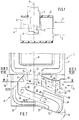
- FIG. 1 is shown schematically how a device 1 in a conduit 2, in which the medium to be measured flows, is installed.
- the device 1 for determining at least one parameter consists of a measuring housing 6, characterized by a lower dash-dot drawn rectangle and a support member 7, characterized by an upper dash-dotted line rectangle in which z. B. an evaluation is housed.
- a measuring element ( Fig. 2 ), which determines, for example, the volume flow of the flowing medium. Further parameters which can be measured are, for example, the pressure, the temperature, a concentration of a medium constituent or a flow velocity, which are determined by means of suitable sensors.
- the measuring housing 6 and the support member 7 have a common longitudinal axis 8, which extends in the installation direction and the z. B. may also be the central axis.
- the device 1 is introduced, for example pluggable in a wall 5 of the line 2.
- the wall 5 defines a flow cross-section of the conduit 2, in the middle of which a central axis 4 extends parallel to the wall 5 in the direction of the flowing medium.
- the direction of the flowing medium hereinafter referred to as the main flow direction is indicated by corresponding arrows 3 and runs there from left to right.
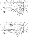
- FIG. 2 shows an exemplary embodiment of the measuring housing 6 with a channel 20 without a cover closing the channel 20 (not shown).
- the channel 20 is formed by a bottom part 42 and a lid.
- the main flow direction 3 of the medium is indicated by arrows.
- the channel 20 consists, for example, of an inlet channel 13 into which the flowing Medium flows in, a deflection channel 15, in which the flowing medium is deflected, and an outlet channel 19.
- the flow directions 25, 26 in the inlet 13 and outlet channel 19 are also indicated by arrows.
- An inlet channel centerline 23 is here curved, for example, since the edge surfaces 35 of the inlet channel 13 are streamlined.
- the outlet channel centerline 22 is here, for example, a straight line.
- the channel 20 may also be formed without deflection channel and outlet channel, for example, a slightly curved or rectilinear passage from the inlet opening 11 in the main flow direction 3. Any other channel shape is conceivable, also a vertical to the longitudinal axis 8 course.
- a flow obstruction 24 is provided, which causes a channel-effective, defined flow separation.
- a bow 69 of the measuring housing 6 is shaped so that solid or liquid particles are reflected away from the inlet opening 11.
- the bow 69 is inclined in an opposite direction to the carrier part 7.
- an edge surface 40 is inclined at an angle ⁇ counter to the main flow direction 3.
- the angle ⁇ can be in the range of about 30 to 60 °, ideally it is about 45 °.
- the edge surface 40 has a width br, which corresponds to at least two thirds of the width b of the inlet opening 11 of the inlet channel 13.
- an opening 18 is further provided, which establishes a connection to a device 1 flowing around the medium. It can also be multiple openings.
- the opening (s) may be located on sidewalls 41 and / or may lead to a lower outer surface 21 of the measuring housing 6 of the device 1 having the channel 20 for connection to the conduit 2, thereby improving the pulsation behavior, ie the device as well accurately measures with pulsating media problems.
- the outlet opening 12, for example has a larger cross-section than the outlet channel 19, whereby the pulsation behavior is improved.
- At least one measuring element 10 is accommodated, for example, in a sensor carrier 9, which projects into the inlet channel 13.
- the part of the channel 20 in which the measuring element 10 is arranged is also referred to as the measuring channel 17.
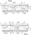
- FIG. 3 shows a section along the line III-III of FIG. 2 .
- a medium flows in addition to gas components, such.
- Air may also contain other ingredients such as liquid particles 50 or dust particles. If these particles get to the measuring element 10, they can damage this.
- a particle deflection element 55 is arranged upstream of the measuring element 10.
- the element 55 is an elevation 60. Liquid particles 50 flowing in the main flow direction 3 and other particles hit this elevation 60, which at least partially obscures the measuring element 10 in the main flow direction 3, and deflects the particles so that they move past the measuring element 10 or already upstream of the measuring element 10 through an example existing particle outlet 67 leave the channel 20.
- a liquid wall film 61 which tears off at the top of the survey as a large drop through the flow in the inlet channel 13 and in an example in one of the collection 60 approximately opposite edge surface 35 existing bulge 63 of the inlet channel 13 is entrained ,
- the bulge 63 is adapted approximately to the outer shape of the elevation 60, for example.
- the bulge 63 also forms a liquid wall film 61, which the medium stagnation moves downstream along the edge surface 25. Downstream of the Bulge 63, but at least before or on the same axial length with the measuring element 10, is for example the Pumbleauslassö réelle 67, through which the particles, in particular the liquid particles 50, the inlet channel 13 can leave again.
- the measuring element 10 is thus protected from particle loading.
- the particle outlet opening 67 is here arranged between a flat area of the wall 35 and a curved area of the wall 35. Particles also exit the inlet channel 13, in part, directly after being deflected by the element 55 or through the elevation 60.
- An inflow surface of the elevation 60 directed counter to the medium flows forms an intersection angle ⁇ with the main flow direction 3.
- the bulge 63 forms a cutting angle ⁇ with the main flow direction 3.
- the cutting angles are in the range of 0 to 90 °, i. the survey 60 and the bulge 63 are formed inclined in the main flow direction 3.
- FIG. 4 shows a section along the line IV-IV of FIG. 2 .
- the bulge 63 has a saddle point 71, which has the greatest distance to a plane which is formed by the central axis 4 and the longitudinal axis 8 and in which the measuring element 10 is located.
- the outlet opening 67 may be located at any point between the saddle point 71 and a downstream end of the measuring element 10.
- the particle outlet port 67 is disposed within a curved portion of the wall 35.
- FIG. 5 shows a section along the line VV of FIG. 2 for a further embodiment.
- the wall 35 of the inlet channel 13 extends here except for a transition region 79 parallel to a plane which is formed by the central axis 4 and the longitudinal axis 8.
- the inlet channel 13 has a front portion 75 which is shifted by a distance d in a direction perpendicular to the central axis 4 and longitudinal axis 8 with respect to a rear portion 77 of the inlet channel 13 so that the survey 60 shields the measuring element 10 even more.
- the transition region 79 is between the front region 75 and the rear region 77, in which at least one particle outlet opening 67 is formed on the side of the elevation 60 opposite edge surface 35.
- FIG. 6a, b shows further embodiments of the invention.
- the channel 20 for example, two elements 55 are arranged for particle deflection. There may also be more elements 55 available.
- the elements 55 are formed, for example, each by a survey 60.
- the elevations 60 are arranged, for example, on opposite edge surfaces 35 of the channel 20 and in the flow direction 3 one behind the other.
- at least one particle outlet opening 67 is provided in the wall 5, through which the foreign particles, in particular the liquid particles 50, can enter the line 2.
- FIG. 6b shows a further variant of FIG. 6a ,
- the elements 55 are arranged approximately at the same axial height in the channel 20. Accordingly, the two Prismauslassö réelleen 67 are arranged opposite one another.
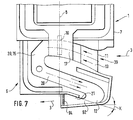
- FIG. 7 shows a further embodiment of the invention.
- a pulsation channel 92 improves the measuring behavior of the measuring element 10 during pulsations occurring in the line 2.
- the flowing medium leaves the pulsation channel 92, for example, in the direction of the main flow direction 3.
- an oil condensation grid 94 is arranged, which prevents oil from entering the channel 20 when backflows occur. This happens because on correspondingly large grid inner surfaces of the lattice openings forming walls precipitates the oil.
- One or more oil condensation grids 94 may also be disposed in each other inlet 11 or outlet opening 12, 67.
Landscapes
- Engineering & Computer Science (AREA)
- Physics & Mathematics (AREA)
- Fluid Mechanics (AREA)
- General Physics & Mathematics (AREA)
- Manufacturing & Machinery (AREA)
- Chemical & Material Sciences (AREA)
- Combustion & Propulsion (AREA)
- Mechanical Engineering (AREA)
- General Engineering & Computer Science (AREA)
- Measuring Volume Flow (AREA)
Applications Claiming Priority (3)
| Application Number | Priority Date | Filing Date | Title |
|---|---|---|---|
| DE10042400 | 2000-08-30 | ||
| DE10042400A DE10042400A1 (de) | 2000-08-30 | 2000-08-30 | Vorrichtung zur Bestimmung zumindest eines Parameters eines strömenden Mediums |
| PCT/DE2001/003258 WO2002018886A1 (de) | 2000-08-30 | 2001-08-25 | Vorrichtung zur bestimmung zumindest eines parameters eines strömenden mediums |
Publications (2)
| Publication Number | Publication Date |
|---|---|
| EP1315950A1 EP1315950A1 (de) | 2003-06-04 |
| EP1315950B1 true EP1315950B1 (de) | 2018-04-25 |
Family
ID=7654173
Family Applications (1)
| Application Number | Title | Priority Date | Filing Date |
|---|---|---|---|
| EP01967026.4A Expired - Lifetime EP1315950B1 (de) | 2000-08-30 | 2001-08-25 | Vorrichtung zur bestimmung zumindest eines parameters eines strömenden mediums |
Country Status (8)
Families Citing this family (33)
| Publication number | Priority date | Publication date | Assignee | Title |
|---|---|---|---|---|
| DE10135142A1 (de) * | 2001-04-20 | 2002-10-31 | Bosch Gmbh Robert | Vorrichtung zur Bestimmung zumindest eines Parameters eines in einer Leitung strömenden Mediums |
| EP1418407B1 (en) * | 2001-07-18 | 2013-06-19 | Hitachi, Ltd. | Equipment for measuring gas flow rate |
| JP3709385B2 (ja) * | 2002-07-01 | 2005-10-26 | 株式会社日立製作所 | 内燃機関用気体流量測定装置 |
| DE10230531B4 (de) * | 2002-07-05 | 2018-01-18 | Robert Bosch Gmbh | Vorrichtung zur Bestimmung wenigstens eines Parameters eines in einer Leitung strömenden Mediums |
| DE10245965B4 (de) * | 2002-09-30 | 2021-06-02 | Robert Bosch Gmbh | Vorrichtung zur Bestimmung wenigstens eines Parameters eines in einer Leitung strömenden Mediums |
| DE10246069A1 (de) * | 2002-10-02 | 2004-04-15 | Robert Bosch Gmbh | Vorrichtung zur Bestimmung wenigstens eines Parameters eines in einer Leitung strömenden Mediums |
| DE10253970A1 (de) * | 2002-11-20 | 2004-06-03 | Robert Bosch Gmbh | Vorrichtung zur Bestimmung wenigstens eines Parameters eines in einer Leitung strömenden Mediums |
| DE102007019282A1 (de) * | 2007-04-24 | 2008-11-06 | Robert Bosch Gmbh | Vorrichtung zur Messung strömender Medien |
| DE102007021025A1 (de) * | 2007-05-04 | 2008-11-06 | Continental Automotive Gmbh | Luftmassenmesser |
| JP4412357B2 (ja) | 2007-06-14 | 2010-02-10 | 株式会社デンソー | 空気流量測定装置 |
| DE102008049843B4 (de) * | 2008-10-01 | 2010-10-14 | Continental Automotive Gmbh | Luftmassensensor |
| JP5168223B2 (ja) | 2009-05-01 | 2013-03-21 | 株式会社デンソー | 空気流量測定装置 |
| DE102010011490A1 (de) * | 2010-03-16 | 2011-09-22 | Hella Kgaa Hueck & Co. | Vorrichtung zur Messung verschäumter Medien |
| US8549908B2 (en) * | 2010-06-17 | 2013-10-08 | Los Robles Advertising, Inc. | Thermal anemometer flow meter for the measurement of wet gas flow |
| DE102011005768A1 (de) * | 2011-03-18 | 2012-09-20 | Robert Bosch Gmbh | Vorrichtung zur Erfassung mindestens einer Eigenschaft eines fluiden Mediums |
| US8607642B2 (en) * | 2011-12-17 | 2013-12-17 | Los Robles Advertising, Inc. | Heated wet gas flow meter |
| JP5852978B2 (ja) * | 2013-03-12 | 2016-02-03 | 日立オートモティブシステムズ株式会社 | 熱式流量計 |
| JP2015068794A (ja) * | 2013-09-30 | 2015-04-13 | 日立オートモティブシステムズ株式会社 | 熱式流量計 |
| DE102014201213A1 (de) * | 2014-01-23 | 2015-07-23 | Robert Bosch Gmbh | Sensoranordnung zur Bestimmung wenigstens eines Parameters eines durch eine Kanalstruktur strömenden fluiden Mediums |
| US10222302B1 (en) * | 2014-11-06 | 2019-03-05 | Mayeaux Holding Llc | Cyclonic system for enhanced separation in fluid sample probes and the like |
| US9909956B1 (en) | 2014-12-03 | 2018-03-06 | Mayeaux Holding Llc | Cyclonic system for enhanced separation of fluid samples and the like, and method therefore |
| AT517311B1 (de) * | 2015-06-08 | 2017-03-15 | Universität Linz | Messdüse zur Bestimmung der Dehnviskosität von Polymerschmelzen |
| US11103248B2 (en) | 2015-08-26 | 2021-08-31 | Cilag Gmbh International | Surgical staples for minimizing staple roll |
| US10641630B2 (en) | 2015-09-30 | 2020-05-05 | Hitachi Automotive Systems, Ltd. | Physical quantity detection device |
| JP6463245B2 (ja) * | 2015-09-30 | 2019-01-30 | 日立オートモティブシステムズ株式会社 | 熱式流量計 |
| JP6433408B2 (ja) * | 2015-10-28 | 2018-12-05 | 日立オートモティブシステムズ株式会社 | 熱式流量計 |
| JP6289585B1 (ja) * | 2016-10-25 | 2018-03-07 | 三菱電機株式会社 | 流量測定装置 |
| JP6658659B2 (ja) * | 2017-04-13 | 2020-03-04 | 株式会社デンソー | 物理量計測装置 |
| AT520416B1 (de) * | 2017-08-24 | 2019-07-15 | Avl List Gmbh | Messvorrichtung zum Detektieren einer Messgröße eines partikelbeladenen Fluids |
| WO2019156046A1 (ja) | 2018-02-07 | 2019-08-15 | 株式会社デンソー | 物理量計測装置 |
| JP6995020B2 (ja) * | 2018-06-27 | 2022-01-14 | 日立Astemo株式会社 | 物理量検出装置 |
| JP6686126B2 (ja) * | 2018-12-28 | 2020-04-22 | 日立オートモティブシステムズ株式会社 | 熱式流量計 |
| DE102021203219B3 (de) * | 2021-03-30 | 2022-06-23 | Vitesco Technologies GmbH | Luftmassensensor und Kraftfahrzeug |
Citations (2)
| Publication number | Priority date | Publication date | Assignee | Title |
|---|---|---|---|---|
| WO2001018497A1 (de) * | 1999-09-07 | 2001-03-15 | Robert Bosch Gmbh | Vorrichtung zur messung wenigstens eines parameters eines strömenden mediums |
| WO2001018499A1 (de) * | 1999-09-07 | 2001-03-15 | Robert Bosch Gmbh | Vorrichtung zur messung von zumindest einem parameter eines in einer leitung strömenden mediums |
Family Cites Families (12)
| Publication number | Priority date | Publication date | Assignee | Title |
|---|---|---|---|---|
| JPS6059118U (ja) * | 1983-09-29 | 1985-04-24 | 日産自動車株式会社 | 内燃機関の吸気流量測定装置 |
| US4981035A (en) * | 1989-08-07 | 1991-01-01 | Siemens Automotive L.P. | Dust defelector for silicon mass airflow sensor |
| JPH04291116A (ja) * | 1991-03-20 | 1992-10-15 | Hitachi Ltd | 熱線式空気流量計 |
| GB2310383A (en) | 1993-10-11 | 1997-08-27 | Evans Gerald J | Meter and manifold assembly with particle entrapment recess |
| DE19524634B4 (de) | 1995-07-06 | 2006-03-30 | Robert Bosch Gmbh | Vorrichtung zur Messung der Masse eines strömenden Mediums |
| DE19632198C1 (de) * | 1996-08-09 | 1998-03-12 | Bosch Gmbh Robert | Vorrichtung zur Messung der Masse eines strömenden Mediums |
| JP3527813B2 (ja) * | 1996-09-02 | 2004-05-17 | 株式会社日立製作所 | 発熱抵抗体式空気流量測定装置 |
| DE19735664A1 (de) * | 1997-08-16 | 1999-02-18 | Bosch Gmbh Robert | Filtermodul |
| DE19735891A1 (de) | 1997-08-19 | 1999-02-25 | Bosch Gmbh Robert | Meßvorrichtung zum Messen der Masse eines in einer Leitung strömenden Mediums |
| DE19800573A1 (de) * | 1998-01-09 | 1999-07-15 | Bosch Gmbh Robert | Vorrichtung zur Messung der Masse eines in einer Leitung strömenden Mediums |
| DE19815654A1 (de) * | 1998-04-08 | 1999-10-14 | Bosch Gmbh Robert | Meßvorrichtung zum Messen der Masse eines in einer Leitung strömenden Mediums |
| JP4108842B2 (ja) * | 1998-10-02 | 2008-06-25 | トヨタ自動車株式会社 | エアクリーナ |
-
2000
- 2000-08-30 DE DE10042400A patent/DE10042400A1/de not_active Withdrawn
-
2001
- 2001-08-25 US US10/111,858 patent/US6851309B2/en not_active Expired - Lifetime
- 2001-08-25 EP EP01967026.4A patent/EP1315950B1/de not_active Expired - Lifetime
- 2001-08-25 ES ES01967026.4T patent/ES2680497T3/es not_active Expired - Lifetime
- 2001-08-25 CN CNB018026575A patent/CN1272605C/zh not_active Expired - Lifetime
- 2001-08-25 JP JP2002523563A patent/JP5209837B2/ja not_active Expired - Lifetime
- 2001-08-25 KR KR1020027005343A patent/KR100880549B1/ko not_active Expired - Fee Related
- 2001-08-25 WO PCT/DE2001/003258 patent/WO2002018886A1/de active Application Filing
Patent Citations (2)
| Publication number | Priority date | Publication date | Assignee | Title |
|---|---|---|---|---|
| WO2001018497A1 (de) * | 1999-09-07 | 2001-03-15 | Robert Bosch Gmbh | Vorrichtung zur messung wenigstens eines parameters eines strömenden mediums |
| WO2001018499A1 (de) * | 1999-09-07 | 2001-03-15 | Robert Bosch Gmbh | Vorrichtung zur messung von zumindest einem parameter eines in einer leitung strömenden mediums |
Also Published As
| Publication number | Publication date |
|---|---|
| WO2002018886A1 (de) | 2002-03-07 |
| DE10042400A1 (de) | 2002-03-14 |
| US20030046977A1 (en) | 2003-03-13 |
| CN1272605C (zh) | 2006-08-30 |
| ES2680497T3 (es) | 2018-09-07 |
| JP5209837B2 (ja) | 2013-06-12 |
| KR20020047282A (ko) | 2002-06-21 |
| EP1315950A1 (de) | 2003-06-04 |
| CN1388892A (zh) | 2003-01-01 |
| KR100880549B1 (ko) | 2009-01-30 |
| US6851309B2 (en) | 2005-02-08 |
| JP2004507754A (ja) | 2004-03-11 |
Similar Documents
| Publication | Publication Date | Title |
|---|---|---|
| EP1315950B1 (de) | Vorrichtung zur bestimmung zumindest eines parameters eines strömenden mediums | |
| EP1127249B1 (de) | Vorrichtung zur messung von zumindest einem parameter eines in einer leitung strömenden mediums | |
| WO2002086425A2 (de) | Luftstrommesser mit vorrichtung zur abscheidung fremdpartikel | |
| EP2142890B1 (de) | Vorrichtung zur messung strömender medien | |
| DE3239126C2 (de) | Strömungsmesser für Fluide | |
| WO2001018497A1 (de) | Vorrichtung zur messung wenigstens eines parameters eines strömenden mediums | |
| DE102006045657A1 (de) | Steckfühler mit optimiertem Strömungsauslass | |
| WO2014060161A1 (de) | Sensoranordnung zur bestimmung des feuchtegehalts eines in einer hauptströmungsrichtung strömenden fluiden mediums | |
| DE10245965B4 (de) | Vorrichtung zur Bestimmung wenigstens eines Parameters eines in einer Leitung strömenden Mediums | |
| DE10059421C2 (de) | Vorrichtung zur Bestimmung zumindest eines Parameters eines strömenden Mediums | |
| DE10019149B4 (de) | Vorrichtung zur Bestimmung zumindest eines Parameters eines strömenden Mediums | |
| DE19942501A1 (de) | Vorrichtung zur Messung von zumindest einem Parameter eines in einer Leitung strömenden Mediums | |
| EP2976629B1 (de) | Sensorvorrichtung zur erfassung einer feuchte eines strömenden fluiden mediums | |
| DE10015918A1 (de) | Vorrichtung zur Bestimmung von zumindest einem Parameter eines in einer Leitung strömenden Mediums | |
| EP1224437B1 (de) | Schutzgitter für massendurchflusssensor in einem ansaugluftkanal | |
| DE112018002084T5 (de) | Messvorrichtung für physikalische Größe | |
| DE3636930A1 (de) | Verfahren und vorrichtung zum fuehlen des durchflusses von fluiden | |
| DE10035543C2 (de) | Vorrichtung zur Bestimmung zumindest eines Parameters eines strömenden Mediums | |
| DE102014019641A1 (de) | Abgasanlage für eine Brennkraftmaschine |
Legal Events
| Date | Code | Title | Description |
|---|---|---|---|
| PUAI | Public reference made under article 153(3) epc to a published international application that has entered the european phase |
Free format text: ORIGINAL CODE: 0009012 |
|
| 17P | Request for examination filed |
Effective date: 20030331 |
|
| AK | Designated contracting states |
Designated state(s): AT BE CH CY DE DK ES FI FR GB GR IE IT LI LU MC NL PT SE TR |
|
| RBV | Designated contracting states (corrected) |
Designated state(s): DE ES FR GB IT |
|
| 17Q | First examination report despatched |
Effective date: 20080731 |
|
| REG | Reference to a national code |
Ref country code: DE Ref legal event code: R079 Ref document number: 50116663 Country of ref document: DE Free format text: PREVIOUS MAIN CLASS: G01F0001684000 Ipc: F02M0035020000 |
|
| RIC1 | Information provided on ipc code assigned before grant |
Ipc: G01F 5/00 20060101ALI20171220BHEP Ipc: F02D 41/18 20060101ALI20171220BHEP Ipc: G01F 1/684 20060101ALI20171220BHEP Ipc: F02M 35/02 20060101AFI20171220BHEP Ipc: G01F 15/12 20060101ALI20171220BHEP |
|
| GRAP | Despatch of communication of intention to grant a patent |
Free format text: ORIGINAL CODE: EPIDOSNIGR1 |
|
| INTG | Intention to grant announced |
Effective date: 20180126 |
|
| GRAA | (expected) grant |
Free format text: ORIGINAL CODE: 0009210 |
|
| GRAS | Grant fee paid |
Free format text: ORIGINAL CODE: EPIDOSNIGR3 |
|
| AK | Designated contracting states |
Kind code of ref document: B1 Designated state(s): DE ES FR GB IT |
|
| REG | Reference to a national code |
Ref country code: GB Ref legal event code: FG4D Free format text: NOT ENGLISH |
|
| REG | Reference to a national code |
Ref country code: DE Ref legal event code: R096 Ref document number: 50116663 Country of ref document: DE |
|
| REG | Reference to a national code |
Ref country code: FR Ref legal event code: PLFP Year of fee payment: 18 |
|
| REG | Reference to a national code |
Ref country code: ES Ref legal event code: FG2A Ref document number: 2680497 Country of ref document: ES Kind code of ref document: T3 Effective date: 20180907 |
|
| PGFP | Annual fee paid to national office [announced via postgrant information from national office to epo] |
Ref country code: IT Payment date: 20180823 Year of fee payment: 18 Ref country code: FR Payment date: 20180824 Year of fee payment: 18 Ref country code: ES Payment date: 20180921 Year of fee payment: 18 |
|
| PGFP | Annual fee paid to national office [announced via postgrant information from national office to epo] |
Ref country code: GB Payment date: 20180828 Year of fee payment: 18 |
|
| REG | Reference to a national code |
Ref country code: DE Ref legal event code: R097 Ref document number: 50116663 Country of ref document: DE |
|
| RIC2 | Information provided on ipc code assigned after grant |
Ipc: F02M 35/02 20060101AFI20171220BHEP Ipc: G01F 1/684 20060101ALI20171220BHEP Ipc: G01F 15/12 20060101ALI20171220BHEP Ipc: G01F 5/00 20060101ALI20171220BHEP Ipc: F02D 41/18 20060101ALI20171220BHEP |
|
| PLBE | No opposition filed within time limit |
Free format text: ORIGINAL CODE: 0009261 |
|
| STAA | Information on the status of an ep patent application or granted ep patent |
Free format text: STATUS: NO OPPOSITION FILED WITHIN TIME LIMIT |
|
| 26N | No opposition filed |
Effective date: 20190128 |
|
| GBPC | Gb: european patent ceased through non-payment of renewal fee |
Effective date: 20190825 |
|
| PG25 | Lapsed in a contracting state [announced via postgrant information from national office to epo] |
Ref country code: FR Free format text: LAPSE BECAUSE OF NON-PAYMENT OF DUE FEES Effective date: 20190831 |
|
| PG25 | Lapsed in a contracting state [announced via postgrant information from national office to epo] |
Ref country code: IT Free format text: LAPSE BECAUSE OF NON-PAYMENT OF DUE FEES Effective date: 20190825 Ref country code: GB Free format text: LAPSE BECAUSE OF NON-PAYMENT OF DUE FEES Effective date: 20190825 |
|
| REG | Reference to a national code |
Ref country code: ES Ref legal event code: FD2A Effective date: 20210107 |
|
| PG25 | Lapsed in a contracting state [announced via postgrant information from national office to epo] |
Ref country code: ES Free format text: LAPSE BECAUSE OF NON-PAYMENT OF DUE FEES Effective date: 20190826 |
|
| PGFP | Annual fee paid to national office [announced via postgrant information from national office to epo] |
Ref country code: DE Payment date: 20201021 Year of fee payment: 20 |
|
| REG | Reference to a national code |
Ref country code: DE Ref legal event code: R071 Ref document number: 50116663 Country of ref document: DE |