EP1315556B1 - Reacteur nucleaire - Google Patents
Reacteur nucleaire Download PDFInfo
- Publication number
- EP1315556B1 EP1315556B1 EP01963308A EP01963308A EP1315556B1 EP 1315556 B1 EP1315556 B1 EP 1315556B1 EP 01963308 A EP01963308 A EP 01963308A EP 01963308 A EP01963308 A EP 01963308A EP 1315556 B1 EP1315556 B1 EP 1315556B1
- Authority
- EP
- European Patent Office
- Prior art keywords
- outlet
- inlet
- recuperator
- reactor
- conditioning system
- Prior art date
- Legal status (The legal status is an assumption and is not a legal conclusion. Google has not performed a legal analysis and makes no representation as to the accuracy of the status listed.)
- Expired - Lifetime
Links
- 230000003750 conditioning effect Effects 0.000 claims abstract description 39
- 238000011144 upstream manufacturing Methods 0.000 claims abstract description 10
- 239000000203 mixture Substances 0.000 claims abstract description 6
- 239000002826 coolant Substances 0.000 claims description 28
- 239000012530 fluid Substances 0.000 claims description 19
- 238000000034 method Methods 0.000 claims description 19
- 238000004891 communication Methods 0.000 claims description 4
- XLYOFNOQVPJJNP-UHFFFAOYSA-N water Substances O XLYOFNOQVPJJNP-UHFFFAOYSA-N 0.000 abstract description 16
- 239000007789 gas Substances 0.000 description 97
- 239000001307 helium Substances 0.000 description 32
- 229910052734 helium Inorganic materials 0.000 description 32
- SWQJXJOGLNCZEY-UHFFFAOYSA-N helium atom Chemical compound [He] SWQJXJOGLNCZEY-UHFFFAOYSA-N 0.000 description 32
- 239000000446 fuel Substances 0.000 description 7
- 238000001816 cooling Methods 0.000 description 5
- 230000004992 fission Effects 0.000 description 5
- 238000012423 maintenance Methods 0.000 description 5
- 238000010248 power generation Methods 0.000 description 5
- 238000012546 transfer Methods 0.000 description 4
- 239000000919 ceramic Substances 0.000 description 2
- 229910010293 ceramic material Inorganic materials 0.000 description 2
- 230000001276 controlling effect Effects 0.000 description 2
- 238000002955 isolation Methods 0.000 description 2
- 239000000463 material Substances 0.000 description 2
- 239000011159 matrix material Substances 0.000 description 2
- 238000006243 chemical reaction Methods 0.000 description 1
- 238000010438 heat treatment Methods 0.000 description 1
- 230000035515 penetration Effects 0.000 description 1
- 230000001105 regulatory effect Effects 0.000 description 1
- 238000013517 stratification Methods 0.000 description 1
Images
Classifications
-
- G—PHYSICS
- G21—NUCLEAR PHYSICS; NUCLEAR ENGINEERING
- G21C—NUCLEAR REACTORS
- G21C15/00—Cooling arrangements within the pressure vessel containing the core; Selection of specific coolants
- G21C15/18—Emergency cooling arrangements; Removing shut-down heat
- G21C15/182—Emergency cooling arrangements; Removing shut-down heat comprising powered means, e.g. pumps
-
- G—PHYSICS
- G21—NUCLEAR PHYSICS; NUCLEAR ENGINEERING
- G21C—NUCLEAR REACTORS
- G21C1/00—Reactor types
- G21C1/04—Thermal reactors ; Epithermal reactors
- G21C1/06—Heterogeneous reactors, i.e. in which fuel and moderator are separated
- G21C1/07—Pebble-bed reactors; Reactors with granular fuel
-
- B—PERFORMING OPERATIONS; TRANSPORTING
- B01—PHYSICAL OR CHEMICAL PROCESSES OR APPARATUS IN GENERAL
- B01F—MIXING, e.g. DISSOLVING, EMULSIFYING OR DISPERSING
- B01F25/00—Flow mixers; Mixers for falling materials, e.g. solid particles
- B01F25/20—Jet mixers, i.e. mixers using high-speed fluid streams
- B01F25/23—Mixing by intersecting jets
-
- B—PERFORMING OPERATIONS; TRANSPORTING
- B01—PHYSICAL OR CHEMICAL PROCESSES OR APPARATUS IN GENERAL
- B01F—MIXING, e.g. DISSOLVING, EMULSIFYING OR DISPERSING
- B01F35/00—Accessories for mixers; Auxiliary operations or auxiliary devices; Parts or details of general application
- B01F35/90—Heating or cooling systems
-
- Y—GENERAL TAGGING OF NEW TECHNOLOGICAL DEVELOPMENTS; GENERAL TAGGING OF CROSS-SECTIONAL TECHNOLOGIES SPANNING OVER SEVERAL SECTIONS OF THE IPC; TECHNICAL SUBJECTS COVERED BY FORMER USPC CROSS-REFERENCE ART COLLECTIONS [XRACs] AND DIGESTS
- Y02—TECHNOLOGIES OR APPLICATIONS FOR MITIGATION OR ADAPTATION AGAINST CLIMATE CHANGE
- Y02E—REDUCTION OF GREENHOUSE GAS [GHG] EMISSIONS, RELATED TO ENERGY GENERATION, TRANSMISSION OR DISTRIBUTION
- Y02E30/00—Energy generation of nuclear origin
- Y02E30/30—Nuclear fission reactors
-
- Y—GENERAL TAGGING OF NEW TECHNOLOGICAL DEVELOPMENTS; GENERAL TAGGING OF CROSS-SECTIONAL TECHNOLOGIES SPANNING OVER SEVERAL SECTIONS OF THE IPC; TECHNICAL SUBJECTS COVERED BY FORMER USPC CROSS-REFERENCE ART COLLECTIONS [XRACs] AND DIGESTS
- Y02—TECHNOLOGIES OR APPLICATIONS FOR MITIGATION OR ADAPTATION AGAINST CLIMATE CHANGE
- Y02P—CLIMATE CHANGE MITIGATION TECHNOLOGIES IN THE PRODUCTION OR PROCESSING OF GOODS
- Y02P70/00—Climate change mitigation technologies in the production process for final industrial or consumer products
- Y02P70/10—Greenhouse gas [GHG] capture, material saving, heat recovery or other energy efficient measures, e.g. motor control, characterised by manufacturing processes, e.g. for rolling metal or metal working
Definitions
- recuperator is to be given a wide meaning and includes a heat transfer means which enables a hot fluid leaving a reactor vessel, or the like, to be utilised in heating incoming fluid for the reactor vessel, the outgoing hot fluid and incoming colder fluid passing through respective hot and cold sides in which outgoing and return fluid flow paths are defined in the heat transfer means and heat being transferred therebetween.
- recuperator-like is to be given a corresponding meaning.
- a method of mixing two fluid streams which includes feeding the two fluid streams to be mixed into a mixing chamber so that the streams enter the chamber at right angles to one another.
- the method may include extracting the mixture from the mixing chamber from a position which is angularly spaced from at least one of the inlet streams.
- the streams may be of gas, typically helium, at different temperatures, the hotter stream being fed into the mixing chamber through a hot inlet, the cooler stream being fed into the mixing chamber through a cold inlet and the mixture being exhausted from the mixing chamber through an outlet.
- gas typically helium
- the method may include feeding the cooler stream into the mixing chamber and exhausting the mixture from the mixing chamber at diametrically opposed positions.
- the mixing device may include a first inlet and a second inlet which are perpendicular to one another, the outlet being positioned opposite one of the inlets.
- a method according to the invention is provided in claim 6.
- the Applicant is aware of a nuclear power plant having a high temperature gas cooled reactor which plant makes use of a thermodynamic conversion cycle based on the Brayton cycle. The Applicant believes that the invention will find application particularly in a plant of this type to remove decay heat when the Brayton cycle is not operational.
- the method may include limiting the temperature of the coolant, typically helium, to the hot side of the recuperator to a predetermined maximum temperature.
- Limiting the temperature of coolant being fed to the hot side of the recuperator may include mixing hot coolant from the reactor with cold coolant prior to feeding the mixture into the hot side of the recuperator.
- the method may include mixing the hot coolant and the cold coolant in a mixing device of the type described above, the outlet of which is connected to the hot side inlet of the recuperator.
- a core conditioning system according to claim 1.
- a nuclear power plant comprising the core conditioning system.
- the system/plant may include a mixing device positioned upstream of the hot side of the recuperator whereby hot coolant from the reactor can be mixed with cold coolant, typically from the second heat exchanger, before being fed into the recuperator. In this way, the maximum temperature of the coolant being fed into the recuperator can be regulated.
- the mixing device may be a mixing device as described above, a first inlet of the mixing device being connected to the outlet of the reactor, the outlet of the mixing device being connected to the hot inlet of the recuperator and a second inlet of the mixing device being connected or connectable to the outlet of the second heat exchanger, the core conditioning system including valving to regulate the flow of coolant from the outlet of the second heat exchanger to the mixing device. This permits the ratio of hot and cold coolant and hence the temperature of the coolant exiting the mixing device and entering the hot side of the recuperator to be controlled.
- the core conditioning system may include at least two sets of heat exchangers connected in parallel.
- a blower may be associated with the or each set of heat exchangers.
- Each set of heat exchangers will typically be capable of removing the decay heat from the reactor on its own thereby improving safety and facilitating maintenance.
- the nuclear reactor may, as mentioned above, be of a high temperature gas cooled type.
- the nuclear reactor may be a reactor known as a Pebble Bed Reactor in which a fuel, comprising a plurality of spherical fuel elements, is used.
- the fuel elements may comprise spheres of fissionable material and a ceramic matrix, or encapsulated in the ceramic material.
- the reactor may be helium cooled.
- the reactor may generate heat energy by means of a controlled nuclear fission process and convert heat energy into electrical energy utilising a thermodynamic process based on a Brayton direct gas cycle. Then, the reactor may utilise substantially pure helium gas as a working fluid. It will be appreciated that the working fluid will then also comprise the coolant fluid.
- the recuperator is a gas-to- gas heat exchanger.
- the recuperator may be a plate compact fin heat exchanger, of a known type.
- the second heat exchanger may be a tube heat exchanger and may be water cooled.
- the helium blower may be supported on magnetic bearings and may be driven by an electric motor.
- The, core conditioning system, and more particularly the hot inlet of the recuperator may be connected to the outlet of the reactor by means of an outlet gas flow duct in which the mixing chamber is mounted.
- the hot outlet of the recuperator may be connected to a gas inlet of the second heat exchanger by means of a first intermediate gas flow duct.
- the cold inlet of the recuperator may be connected to a gas outlet of the second heat exchanger by means of a second intermediate gas flow duct.
- the cold outlet of the recuperator may be connected to an inlet of the reactor by means of an inlet gas flow duct.
- a normal gas flow path may be defined from the outlet to the inlet of the reactor by means of the outlet gas flow duct via the hot side of the recuperator to the first intermediate gas flow duct via the second heat exchanger to the second intermediate gas flow duct and via the cold side of the recuperator to the inlet gas flow duct and inlet of the reactor.
- An inlet valve may be arranged on the second intermediate gas flow duct for controlling gas flow between the second heat exchanger and the cold inlet of the recuperator.
- a branch flow duct may be arranged intermediate the second intermediate gas flow duct and the inlet gas flow duct and a first by-pass valve may be arranged thereon.
- the branch flow duct may be connected to a second inlet of the mixing device. Then, by means of the first by-pass valve of the branch flow duct, cooler gas may be mixed in the mixing chamber with hot gas from the hot plenum of the reactor entering the mixing chamber of the mixing device to provide gas of a predetermined temperature to the hot inlet of the recuperator.
- a by-pass duct may be arranged intermediate the branch flow duct and the inlet gas flow duct and may have a second by-pass valve arranged thereon. It will be appreciated that by manipulation of the inlet valve and the first and second by-pass valves, cool gas from the outlet of the second water cooled heat exchanger may be diverted directly to the inlet gas flow duct and directed to the cold plenum of the reactor, thereby effectively bypassing the return flow path of the recuperator.
- hot core gas is extracted from the hot plenum in the core of the nuclear reactor and transported to the hot inlet of the recuperator.
- the gas is mixed in the mixing chamber with a portion of cold gas leaving the second heat exchanger. This is done to ensure that the gas temperature entering the recuperator never exceeds the maximum temperature limits of the recuperator, typically 900°C.
- the helium temperature is reduced further before it enters the second heat exchanger. Heat is removed from the system in the second heat exchanger. Cold helium leaving the second heat exchanger then enters the blower and continues to the cold inlet of the recuperator. If desired, a portion of the cool gas is diverted to the mixing device and mixed with hot gas entering the mixing chamber, as described above.
- the remaining gas stream then enters the cold inlet of the recuperator where its temperature is increased by heat transfer from the hot inlet gas flowing through the hot side of the recuperator.
- the heated gas stream is transported to the reactor cold plenum via the reactor inlet.
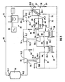
- reference numeral 10 refers generally to part of a nuclear power plant in accordance with the invention.
- the nuclear power plant 10 includes a closed loop power generation circuit, generally indicated by reference numeral 12.
- the power generation circuit 12 includes a nuclear reactor 14, a high pressure turbine 16, a low pressure turbine 18, a power turbine 20, a recuperator 22, a pre-cooler 24, a low pressure compressor 26, an inter-cooler 28 and a high pressure compressor 30.
- the reactor 14 is a pebble bed reactor making use of spherical fuel elements.
- the reactor 14 has an inlet 14.1 and an outlet 14.2.
- the high pressure turbine 16 is drivingly connected to the high pressure compressor 30 and has an upstream side or inlet 16.1 and a downstream side or outlet 16.2, the inlet 16.1 being connected to the outlet 14.2 of the reactor 14.
- the low pressure turbine 18 is drivingly connected to the low pressure compressor 26 and has an upstream side or inlet 18.1 and a downstream side or outlet 18.2.
- the inlet 18.1 is connected to the outlet 16.2 of the high pressure turbine 16.
- the nuclear power plant 10 includes a generator, generally indicated by reference numeral 32 to which the power turbine 20 is drivingly connected.
- the power turbine 20 includes an upstream side or inlet 20.1 and a downstream side or outlet 20.2.
- the inlet 20.1 of the power turbine 20 is connected to the outlet 18.2 of the low pressure turbine 18.
- a variable resistor bank 33 is disconnectably connectable to the generator 32.
- the recuperator 22 has a hot or low pressure side 34 and a cold or high pressure side 36.
- the low pressure side of the recuperator 34 has an inlet 34.1 and an outlet 34.2.
- the inlet 34.1 of the low pressure side is connected to the outlet 20.2 of the power turbine 20.
- the pre-cooler 24 is a water to helium heat exchanger and includes a helium inlet 24.1 and a helium outlet 24.2.
- the inlet 24.1 of the pre-cooler 24 is connected to the outlet 34.2 of the low pressure side 34 of the recuperator 22.
- the low pressure compressor 26 has an upstream side or inlet 26.1 and a downstream side or outlet 26.2.
- the inlet 26.1 of the low pressure compressor 26 is connected to the helium outlet 24.2 of the pre-cooler 24.
- the inter-cooler 28 is a helium to water heat exchanger and includes a helium inlet 28.1 and a helium outlet 28.2.
- the helium inlet 28.1 is connected to the outlet 26.2 of the low pressure compressor 26.
- the high pressure compressor 30 includes an upstream side or inlet 30.1 and a downstream side or outlet 30.2.
- the inlet 30.1 of the high pressure compressor 30 is connected to the helium outlet 28.2 of the inter-cooler 28.
- the outlet 30.2 of the high pressure compressor 30 is connected to an inlet 36.1 of the high pressure side of the recuperator 22.
- An outlet 36.2 of the high pressure side of the recuperator 22 is connected to the inlet 14.1 of the reactor 14.
- the nuclear power plant 10 includes a start-up blower system generally indicated by reference numeral 38 connected between the outlet 34.2 of the low pressure side 34 of the recuperator 22 and the inlet 24.1 of the pre-cooler 24.
- the start-up blower system 38 includes a normally open start-up blower system in-line valve 40 which is connected in-line between the outlet 34.2 of the low pressure side of the recuperator and the inlet 24.1 of the pre-cooler 24.
- Two blowers 42 are connected in parallel with the start-up blower system in-line valve 40 and a normally closed isolation valve 44 is associated with and connected in series with each blower 42.
- a low pressure compressor bypass line 46 extends from a position between the outlet or downstream side 26.2 of the low pressure compressor 26 and the inlet 28.1 of the inter-cooler 28 to a position between the start-up blower system 38 and the inlet 24.1 of the pre-cooler 24.
- a normally closed low pressure bypass valve 48 is mounted in the low pressure compressor bypass line 46.
- a high pressure compressor bypass line 50 extends from a position between the outlet or downstream side 30.2 of the high pressure compressor and the inlet 36.1 of the high pressure side 36 of the recuperator 22 to a position between the outlet or downstream side 26.2 of the low pressure compressor 26 and the inlet 28.1 of the inter-cooler 28.
- a normally closed high pressure bypass valve 51 is mounted in the high pressure compressor bypass line 50.
- a recuperator bypass line 52 extends from a position upstream of the inlet 36.1 of the high pressure side 36 of the recuperator 22 to a position downstream of the outlet 36.2 of the high pressure side 36 of the recuperator 22.
- a normally closed recuperator bypass valve 54 is mounted in the recuperator bypass line 52.
- the plant 10 includes a high pressure coolant valve 56 and a low pressure coolant valve 58.
- the high pressure coolant valve 56 is configured, when open, to provide a bypass of helium from the high pressure side or outlet 30.2 of the high pressure compressor 30 to the inlet or low pressure side 18.1 of the low pressure turbine 18.
- the low pressure coolant valve 58 is configured, when open, to provide a bypass of helium from the high pressure side or outlet 30.2 of the high pressure compressor 30 to the inlet 20.1 of the power turbine 20.
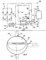
- the plant 10 also includes a core conditioning system, generally indicated by reference numeral 100 ( Figure 2 ) connected in series with the reactor 14.
- the core conditioning system is connected to an outlet 14.2 via a hot feed pipe or outlet gas flow duct 102 and to an inlet of the reactor via a cold return pipe 104 or inlet flow duct.
- the hot feed pipe 102 is connected at an upstream end thereof, to a core outlet plenum and the cold return pipe 104 is connected, at a downstream end thereof, to a core inlet plenum (not shown in Figure 1 ).
- the core conditioning system 100 includes a gas-to-gas heat exchanger or recuperator 106 which has a hot side 108 and a cold side 110.
- the hot side has an inlet 108.1 and an outlet 108.2.
- the cold side 110 has an inlet 110.1 and an outlet 110.2.
- the core conditioning system 100 further includes a water-to-gas heat exchanger 112 having a gas inlet 112.1 and a gas outlet 112.2.
- the core conditioning system 100 includes a blower arrangement, generally indicated by reference numeral 114.
- the blower arrangement 114 includes three blowers 116 which are connected in parallel and a blower isolation valve 118 connected in series with each of the blowers 116.
- the core conditioning system 100 further includes a mixing device 120.
- the mixing device 120 includes a body 122 which defines a spherical mixing chamber 124.
- a hot inlet 126 leads into the mixing chamber 124 and is connected to a feed pipe 102 or outlet gas flow duct.
- a cold inlet 128 leads into the mixing chamber 124 at a position which is at 90° to the hot inlet 126.
- An outlet 130 leads from the mixing chamber 124 and is connected to the inlet 108.1 of the hot side 108 of the recuperator 106.
- the core conditioning system 100 further includes a blower bypass valve 132, a flow valve 134, a mixing valve 136 and a recuperator bypass valve 138.
- the purpose of the core conditioning system is to remove decay heat from the reactor when the reactor is shut down and the Brayton cycle is not operational. In the event of a trip of the power generation circuit, the core conditioning system serves to cool the reactor down to a temperature that will allow a restart. In a restart the start-up blower system 38 provides the required core mass flow to remove the core fission heat.
- the function of the core conditioning system recuperator 106 is to ensure that the temperature of the returning gas to the reactor does not decrease below acceptable limits. At the same time, it reduces the inlet temperature to the heat exchanger 112.
- the mixing device 120 is provided to limit the temperature of gas being fed to the inlet 108.1 of the hot side 108 of the recuperator 106 so that it does not exceed a predetermined maximum temperature, typically 900°C.
- the hot gas from the reactor is fed into the mixing chamber 124 through the hot inlet 126.
- already cooled gas is fed through the cold inlet 1 28 into the mixing chamber 124 where it mixes with the hot gas and is exhausted through the outlet 130 from where it is fed to the hot side of the recuperator.
- the inlets 126 and 128 are directed towards the centre of the spherical mixing chamber 124 and are mutually perpendicular.
- the outlet 130 is positioned diametrically opposite to the cold inlet 128.
- the Inventors believe that the stream of cold gas which is fed into the mixing chamber 124 will penetrate the hot stream. When the combined stream hits the opposite wall of the mixing chamber 124 a swirling motion is induced which results in efficient mixing with very low stratification levels.
- the diameters of the inlet 128 and the outlet 130 can be altered, thereby to alter the velocity of the gas streams being fed into the mixing chamber and hence the momentum thereof to change the level of penetration between the cold gas and hot gas and thereby optimise the mixing process.
- the core conditioning system 100 is preferably housed in a pressure vessel (not shown).
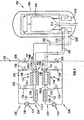
- reference numeral 200 generally refers to another core cooling system or core conditioning system in accordance with the invention.
- the core conditioning system 200 is connected to a nuclear reactor 202 which is a high temperature gas cooled reactor and is of a type known as a Pebble Bed Reactor in which a fuel comprising a plurality of spherical fuel elements (not shown) is used.
- the fuel elements comprise spheres of a fissionable material in a ceramic matrix, encapsulated in the ceramic material.
- the reactor is helium cooled.
- the reactor generates thermal power by means of a controlled nuclear fission process and converts heat energy into electrical energy utilising a thermodynamic process based on a Brayton direct gas cycle.
- the reactor utilises substantially pure helium gas as a working fluid, which also comprises the coolant fluid (not shown) for the reactor core.
- the reactor 202 has a reactor pressure vessel 204 containing a reactor core 206 cooled by helium gas.
- the reactor vessel 204 has inlets 208 and outlets 210.
- the outlets 210 of the reactor vessel 204 are in fluid communication with a hot plenum 212 of the reactor core 206.
- the inlets 208 of the reactor vessel 204 are in fluid communication with a cold plenum 214 of the reactor core 206.
- the core conditioning system 200 which is typically housed in a pressure vessel (not shown), has two sets 220 of heat exchangers. Each set 220 is similar to the heat exchangers of the system 100 and has a recuperator 106 having an inlet 108.1, an outlet 108.2, an inlet 110.1 and an outlet 110.2. The inlet 108.1 is connected to the outlet 210 via an outlet flow duct 102 and the outlet 110.2 is connected to the inlet 208 via an inlet flow duct 104.
- Each recuperator 106 is a multi-tube gas heat exchanger.
- each set 220 has a second heat exchanger 112 operatively connected to its associated recuperator 106 intermediate the inlet 110.1 and outlet 108.2 thereof.
- the second heat exchanger 112 is a printed circuit heat exchanger and is water cooled.
- each set 220 includes a gas mixing device 120 intermediate the outlet 210 and the inlet 108.1 of the recuperator 106.
- Each set 220 also has a helium blower 116 for driving helium gas through the heat exchangers 106 and 112.
- the blower 116 is supported on magnetic bearings (not shown) and is driven by an electric motor.
- each set 220 the outlet 108.2 of the recuperator 106 is connected to a gas inlet 112.2 of its associated second heat exchanger 112 by means of a first intermediate gas flow duct 230.
- the inlet 110.1 of the recuperator 106 is connected to a gas outlet 112.2 of the second heat exchanger 112 by means of a second intermediate gas flow duct 232.
- a gas flow path 234 is defined from the outlet 210 to the inlet 208 by means of the outlet flow duct 102 via the recuperator 106 to the first intermediate gas flow duct 230 via the second heat exchanger 112 to the second intermediate gas flow duct 232 and again via the recuperator 106 to the inlet flow duct 104 and inlet 210.
- An inlet valve 134 is arranged on the second intermediate gas flow duct 232 for controlling gas flow between the second heat exchanger 112 and the inlet 110.1 of the recuperator 106.
- a branch flow duct 236 is arranged intermediate the second intermediate gas flow duct 232 and the outlet flow duct 104 and a first by-pass valve 136 is arranged thereon.
- the branch flow duct 236 is connected to the inlet 128 of the mixing device 120 and the outlet 210 is connected to the inlet 126 of the mixing device 120 via the outlet flow duct 102.
- An outlet 130 of the mixing device 120 is connected to the inlet 108.1 of the recuperator 106.
- cooler gas may be mixed in the device 120 with hot gas from the hot plenum 212 of the reactor 206 entering the mixing device 120 to provide gas of a predetermined temperature to the inlet 108.1 of the recuperator 106.
- a by-pass duct 238 is arranged intermediate the branch flow duct 236 and the inlet gas flow duct 104 and has a second by-pass valve 138 arranged thereon.
- cool gas from the outlet 112.2 of the second water cooled heat exchanger 112 may be diverted directly to the inlet flow duct 104 and directed to the cold plenum 214 of the reactor 206, thereby effectively bypassing the return flow path of the recuperator 106.
- hot core gas is extracted from the hot plenum 212 in the core 206 of the nuclear reactor 202 and transported to the inlet 108.1 of the recuperator 106.
- the recuperator 106 Before it enters the recuperator 106 it is mixed in the mixing device 120 with cold gas leaving the water cooler 112. This is done to ensure that the gas temperature entering the recuperator 106 never exceeds the maximum temperature limits of the recuperator 106.
- the helium temperature is reduced further before it enters the water cooler 112. Heat is removed from the system in the water cooler 112. Cold helium leaving the water cooler 112 then enters the blower 116 and continues to the inlet 110.1 of the recuperator 106.
- a portion of the cool gas is diverted to the mixing device 120 and mixed with hot gas entering the mixing device 120, as described above.
- the remaining gas stream then enters the inlet 110.1 of the recuperator 20 where its temperature is increased by heat transfer from the hot gas flowing through the hot side 108 of the recuperator 106.
- the heated gas stream is transported to the reactor cold plenum 214 via the reactor vessel inlet 208.
- the gas mixing device 120 limits the incoming gas temperature to the recuperator 106.
- the recuperator 106 controls the temperature differential across the reactor core 206 and also reduces the gas temperature entering the water cooled heat exchangers 112.
- the temperature of the helium gas may be reduced to a temperature at which known standard water cooled heat exchangers 112 may be used.
- the blower 116 provides the necessary helium mass flow.
- the core conditioning system pressure vessel (not shown) is preferably coupled directly to the primary pressure boundary of the reactor pressure vessel 204 and its operating pressure is therefore intended to follow that of the primary system.
- the core conditioning system 100, 200 removes core decay heat when the Brayton cycle is not in use and removes core fission heat during start-up operations.
- the average helium temperature at the reactor outlet may be reduced to a level that will allow the restart of the Brayton cycle.
- the average helium temperature at the reactor outlet may be reduced to a level that will allow maintenance operations to take place.
- the core conditioning systems 100, 200 will control the rate at which core fission heat is removed from the core 14, 206 of the reactor and allow controlled heat-up of the reactor core.
- the conditioning system 100, 200 may also be used to permit the increase of the outlet helium temperature to a level at which the Brayton cycle can be initiated.
- helium gas in the core and at the outlet of the reactor may be at a temperature of about 900°C.
- the gas Before the gas enters the recuperator 106 if necessary it is cooled to about 900°C by mixing with the cool gas stream. In the recuperator 106, the gas is cooled to less than 550°C. This enables the use of available industrial blowers 116 and water cooled heat exchangers 112. The gas then enters the water cooler 112 where heat is extracted from the gas and it is cooled to a maximum temperature of about 350°C.
- the gas On re-entering the recuperator 106, the gas is heated before entering the inlet of the reactor so that a desired ratio of inlet to outlet temperatures in the reactor core may be maintained while the core is gradually cooled.
- the recuperator 106 may be removed from the gas flow path, as described above, and further cooling above, and further cooling may be provided by the water cooled heat exchanger 112, if it is required to cool the core completely.
- a nuclear reactor and a nuclear reactor cooling or core conditioning system 100, 200 that allows for the controlled cooling of the reactor core for maintenance. Further, where a Brayton direct gas thermodynamic cycle is used, the conditioning system 100, 200 provides for control of the temperature of the helium working fluid in order to initiate the Brayton cycle.
Landscapes
- Physics & Mathematics (AREA)
- Engineering & Computer Science (AREA)
- Plasma & Fusion (AREA)
- General Engineering & Computer Science (AREA)
- High Energy & Nuclear Physics (AREA)
- Chemical & Material Sciences (AREA)
- Chemical Kinetics & Catalysis (AREA)
- Heat-Exchange Devices With Radiators And Conduit Assemblies (AREA)
- Treatment Of Water By Oxidation Or Reduction (AREA)
- Analysing Materials By The Use Of Radiation (AREA)
Claims (9)
- Système (100) de conditionnement de noyau agencé pour éliminer la chaleur de décroissance générée dans le noyau d'un réacteur nucléaire (14) et agencé pour être relié en série avec ce dernier, le système (100) de conditionnement de noyau étant caractérisé en ce qu'il comprend au moins un récupérateur (106) présentant un côté chaud (108) qui est muni d'un orifice (108.1) d'entrée et d'un orifice (108.2) de sortie et un côté froid (110) qui est muni d'un orifice (110.1) d'entrée et d'un orifice (110.2) de sortie, l'orifice (108.1) d'entrée du côté chaud étant en communication fluidique avec un orifice (14.2) de sortie du réacteur (14) et l'orifice (110.2) de sortie du côté froid étant en communication fluidique avec un orifice (14.1) d'entrée du réacteur (14), et un échangeur thermique (112) relié de manière opérationnelle au récupérateur entre l'orifice (108.2) de sortie du côté chaud et l'orifice (110.1) d'entrée du côté froid.
- Système de conditionnement de noyau selon la revendication 1, comprenant en outre un dispositif mélangeur (30) placé en amont du côté chaud (108) du récupérateur (106) par lequel un liquide de refroidissement chaud provenant du réacteur peut être mélangé avec un liquide de refroidissement froid, avant d'alimenter le récupérateur (106).
- Système de conditionnement de noyau selon la revendication 2, dans lequel le dispositif mélangeur comprend:- une chambre (124) de mélange qui est généralement de forme sphérique ;- un premier orifice (126) d'entrée relié à l'orifice (14.2) de sortie du réacteur (14), et un deuxième orifice (128) d'entrée relié à un orifice (112.2) de sortie de l'échangeur thermique (112) conduisant à la chambre (124) de mélange, les premier et deuxième orifices (126, 128) d'entrée étant perpendiculaires l'un à l'autre, et un orifice (130) de sortie partant de la chambre (124) de mélange et étant relié à l'orifice (108.1) d'entrée du côté chaud du récupérateur (106), les orifices (126, 128) d'entrée étant dirigés vers le centre de la chambre de mélange et l'orifice (130) de sortie étant placé à l'opposé de l'un des orifices (126, 128) d'entrée- le système (100) de conditionnement de noyau comprenant une soupape pour réguler le flux de liquide de refroidissement depuis l'orifice de sortie de l'échangeur thermique (112) jusqu'au dispositif mélangeur (30).
- Système de conditionnement de noyau selon l'une des revendications 1 à 3, dans lequel le système de conditionnement de noyau comprend au moins deux ensembles (220) d'échangeurs thermiques reliés en parallèle.
- Centrale nucléaire comprenant un système de conditionnement de noyau selon l'une des revendications 1 à 4, relié en série avec elle.
- Procédé d'élimination de la chaleur de décroissance générée dans le noyau du réacteur nucléaire (14), lequel procédé consiste à- relier un système (100) de conditionnement de noyau selon l'une des revendications 1 à 4 ; et- faire circuler un liquide de refroidissement entre le réacteur (14) et le système (100) de conditionnement de noyau.
- Procédé selon la revendication 6, qui consiste à limiter la température du liquide de refroidissement alimentant le côté chaud (108) du récupérateur (106) à une température maximum prédéterminée.
- Procédé selon la revendication 7, dans lequel limiter la température d'un liquide de refroidissement alimentant le côté chaud du récupérateur consiste à mélanger un liquide de refroidissement chaud provenant du réacteur (14) avec un liquide de refroidissement froid avant d'alimenter le côté chaud (108) du récupérateur (106) avec le mélange.
- Procédé selon la revendication 8, qui consiste à mélanger le liquide de refroidissement chaud et le liquide de refroidissement froid dans un dispositif mélangeur (30), le dispositif mélangeur (30) comprenant :une chambre (124) de mélange qui est généralement de forme sphérique, etun premier orifice (126) d'entrée relié à l'orifice (14.2) de sortie du réacteur (14), et un deuxième orifice (128) d'entrée relié à un orifice (112.2) de sortie de l'échangeur thermique (112) conduisant à la chambre (124) de mélange, les premier et deuxième orifices (126, 128) d'entrée étant perpendiculaires l'un à l'autre, et un orifice (130) de sortie partant de la chambre (124) de mélange et étant relié à l'orifice (108.1) d'entrée du côté chaud du récupérateur (108), les orifices (126, 128) d'entrée étant dirigés vers le centre de la chambre de mélange et l'orifice (130) de sortie étant placé à l'opposé de l'un des orifices (126, 128) d'entrée.
Applications Claiming Priority (5)
| Application Number | Priority Date | Filing Date | Title |
|---|---|---|---|
| ZA200004635 | 2000-09-04 | ||
| ZA200004635 | 2000-09-04 | ||
| ZA200106068 | 2001-07-24 | ||
| ZA200106068 | 2001-07-24 | ||
| PCT/IB2001/001606 WO2002021537A2 (fr) | 2000-09-04 | 2001-09-03 | Reacteur nucleaire |
Publications (2)
| Publication Number | Publication Date |
|---|---|
| EP1315556A2 EP1315556A2 (fr) | 2003-06-04 |
| EP1315556B1 true EP1315556B1 (fr) | 2009-12-02 |
Family
ID=27145505
Family Applications (1)
| Application Number | Title | Priority Date | Filing Date |
|---|---|---|---|
| EP01963308A Expired - Lifetime EP1315556B1 (fr) | 2000-09-04 | 2001-09-03 | Reacteur nucleaire |
Country Status (10)
| Country | Link |
|---|---|
| US (1) | US20050074083A1 (fr) |
| EP (1) | EP1315556B1 (fr) |
| JP (2) | JP2004508568A (fr) |
| KR (1) | KR100881473B1 (fr) |
| CN (1) | CN1262341C (fr) |
| AT (1) | ATE450310T1 (fr) |
| AU (1) | AU2001284331A1 (fr) |
| CA (1) | CA2421231C (fr) |
| DE (1) | DE60140682D1 (fr) |
| WO (1) | WO2002021537A2 (fr) |
Families Citing this family (12)
| Publication number | Priority date | Publication date | Assignee | Title |
|---|---|---|---|---|
| JP2004525294A (ja) * | 2001-03-26 | 2004-08-19 | ペブル ベッド モジュラー リアクター (プロプライエタリー) リミテッド | 原子力発電所とその操作方法 |
| CA2442719C (fr) * | 2001-03-30 | 2011-10-18 | Pebble Bed Modular Reactor (Proprietary) Limited | Une methode pour conditionner un circuit de production d'energie ou un reacteur de centrale nucleaire |
| CA2440701A1 (fr) * | 2001-05-25 | 2002-11-28 | Pebble Bed Modular Reactor (Proprietary) Limited | Centrale nucleaire a cycle de brayton et procede de demarrage du cycle de brayton |
| AU2002319558A1 (en) * | 2001-07-26 | 2003-02-17 | Pebble Bed Modular Reactor (Proprietary) Limited | A nuclear power plant and a method of regulating the speed of a generator of the plant |
| KR101680727B1 (ko) * | 2010-01-13 | 2016-11-29 | 어드밴스드 리액터 컨셉트 엘엘씨 | 피복된 환형의 금속 핵 연료 |
| RU2713473C2 (ru) * | 2010-02-22 | 2020-02-05 | Эдвансд Риэктор Консептс Ллк | Система ядерного реактора и способ получения ядерной энергии |
| KR200458109Y1 (ko) * | 2010-06-23 | 2012-01-20 | 김원제 | 향기 발산 및 살균 기능을 가지는 배수구 악취 차단 커버 |
| EP2715734B1 (fr) * | 2011-06-03 | 2017-03-08 | Claudio Filippone | Évacuation de chaleur à décroissance passive et procédés correspondants |
| KR102238185B1 (ko) * | 2014-02-26 | 2021-04-09 | 한국과학기술원 | 원자력 발전소의 피동 붕괴열 제거계통 |
| GB2538687B (en) | 2014-04-14 | 2020-12-30 | Advanced Reactor Concepts LLC | Ceramic nuclear fuel dispersed in a metallic alloy matrix |
| CN110491533B (zh) * | 2019-08-22 | 2022-02-22 | 哈尔滨工程大学 | 一种双层冷却堆芯发电系统 |
| CN112614602B (zh) * | 2020-12-11 | 2022-12-27 | 西安交通大学 | 钠冷快堆堆芯出口冲击射流搅混特性模化实验系统及方法 |
Family Cites Families (15)
| Publication number | Priority date | Publication date | Assignee | Title |
|---|---|---|---|---|
| US378894A (en) * | 1888-03-06 | Pocket-rule | ||
| US2989380A (en) * | 1953-11-24 | 1961-06-20 | Exxon Research Engineering Co | Apparatus for carrying out chemical reactions |
| US3210254A (en) * | 1961-02-10 | 1965-10-05 | Gen Dynamics Corp | Heat extraction system for a nuclear reactor |
| DE1272893B (de) * | 1964-07-01 | 1968-07-18 | Combustion Eng | Vorrichtung zum Mischen von unter hohem Druck stehenden Fluessigkeiten |
| CH512808A (de) * | 1970-03-09 | 1971-09-15 | Bbc Brown Boveri & Cie | Kernkraftwerk mit geschlossenem Kühlkreislauf |
| JPS5321804Y1 (fr) * | 1972-03-25 | 1978-06-07 | ||
| US4052260A (en) * | 1975-06-12 | 1977-10-04 | Kernforschungsanlage Julich Gesellschaft Mit Beschrankter Haftung | Method of operating a nuclear-power-generating installation with closed gas cycle and plant operated by this method |
| DE2923639A1 (de) * | 1979-06-11 | 1980-12-18 | Hochtemperatur Reaktorbau Gmbh | Verfahren zum wiederbeladen der kaverne eines reaktordruckbehaelters mit kugelfoermigen betriebselementen |
| DE3030697A1 (de) * | 1980-08-14 | 1982-03-18 | Hochtemperatur-Reaktorbau GmbH, 5000 Köln | Gasgekuehlter kernreaktor |
| DE3335451A1 (de) * | 1983-09-30 | 1985-04-18 | Hochtemperatur-Reaktorbau GmbH, 4600 Dortmund | Kernreaktoranlage |
| JPS61231492A (ja) * | 1985-04-05 | 1986-10-15 | 株式会社東芝 | 原子炉補助設備 |
| GB2216191B (en) * | 1988-03-31 | 1992-08-12 | Aisin Seiki | Gas turbine cogeneration apparatus for the production of domestic heat and power |
| JPH02152532A (ja) * | 1988-12-02 | 1990-06-12 | Minoru Nakamura | 液体混合装置 |
| JP2904590B2 (ja) * | 1990-12-18 | 1999-06-14 | 電気化学工業株式会社 | 混練物の吐出用混合管 |
| US5375151A (en) * | 1991-12-09 | 1994-12-20 | General Electric Company | Reactor water cleanup system |
-
2001
- 2001-09-03 AT AT01963308T patent/ATE450310T1/de not_active IP Right Cessation
- 2001-09-03 KR KR1020037003228A patent/KR100881473B1/ko active IP Right Grant
- 2001-09-03 AU AU2001284331A patent/AU2001284331A1/en not_active Abandoned
- 2001-09-03 CN CNB018168817A patent/CN1262341C/zh not_active Expired - Lifetime
- 2001-09-03 CA CA2421231A patent/CA2421231C/fr not_active Expired - Lifetime
- 2001-09-03 WO PCT/IB2001/001606 patent/WO2002021537A2/fr active Application Filing
- 2001-09-03 US US10/363,366 patent/US20050074083A1/en not_active Abandoned
- 2001-09-03 JP JP2002525666A patent/JP2004508568A/ja active Pending
- 2001-09-03 EP EP01963308A patent/EP1315556B1/fr not_active Expired - Lifetime
- 2001-09-03 DE DE60140682T patent/DE60140682D1/de not_active Expired - Lifetime
-
2012
- 2012-07-12 JP JP2012156181A patent/JP2012194194A/ja active Pending
Also Published As
| Publication number | Publication date |
|---|---|
| CN1468141A (zh) | 2004-01-14 |
| CA2421231A1 (fr) | 2002-03-14 |
| US20050074083A1 (en) | 2005-04-07 |
| WO2002021537A2 (fr) | 2002-03-14 |
| EP1315556A2 (fr) | 2003-06-04 |
| WO2002021537A3 (fr) | 2002-10-10 |
| CN1262341C (zh) | 2006-07-05 |
| AU2001284331A1 (en) | 2002-03-22 |
| KR20030066612A (ko) | 2003-08-09 |
| DE60140682D1 (de) | 2010-01-14 |
| CA2421231C (fr) | 2010-04-20 |
| ATE450310T1 (de) | 2009-12-15 |
| JP2012194194A (ja) | 2012-10-11 |
| JP2004508568A (ja) | 2004-03-18 |
| KR100881473B1 (ko) | 2009-02-05 |
Similar Documents
| Publication | Publication Date | Title |
|---|---|---|
| JP2012194194A (ja) | 原子炉 | |
| EP1374252B1 (fr) | Reacteur nucleaire et procede de conditionnement d'un circuit generateur d'energie dans une centrale electronucleaire | |
| US20110239650A1 (en) | Power plant comprising a turbine unit and a generator | |
| JPH0587651B2 (fr) | ||
| US5425230A (en) | Gas distribution station with power plant | |
| JP2005508492A5 (fr) | ||
| KR20040105851A (ko) | 하나 이상의 고온 원자로의 노심에서 발생된 열로부터전기를 발생시키는 방법 및 장치 | |
| JP2007064049A (ja) | ガスタービンコージェネレーション設備の廃熱回収システム | |
| JP2004508568A5 (fr) | ||
| JPH08177409A (ja) | 蒸気タービンプラント | |
| ZA200301594B (en) | Nuclear reactor. | |
| WO2002080190A1 (fr) | Centrale nucleaire | |
| JP2007107907A (ja) | 高温ガス炉システム及び中間熱交換システム | |
| GB1600080A (en) | Operation of nuclear power plant | |
| RU97121547A (ru) | Способ эксплуатации энергетической установки и установки для его осуществления | |
| Jung et al. | Thermal-hydraulic Design of 9.5 MWT Decay Heat Removal System in SFR | |
| Yoo et al. | A Study on Supercritical CO2 Brayton Cycle for a Molten Salt Reactor | |
| Tilliette et al. | An efficient, flexible arrangement to generate high quality process or domestic heat in recuperative gas cycle power plants: application to helium direct cycle nuclear power plants | |
| JPS6047997B2 (ja) | 原子炉の冷却装置 | |
| JPH06281289A (ja) | コージェネレーション装置 | |
| CA2037418A1 (fr) | Systeme de refroidissement passif a l'arret pour reacteurs nucleaires | |
| ZA200307279B (en) | A nuclear power plant and a method of conditioning its power generation circuit. | |
| JPH0686533A (ja) | Mhd発電用シード回収装置 | |
| KR20170054366A (ko) | 초임계 이산화탄소 발전 시스템 | |
| JPH06257416A (ja) | コンバインドサイクル発電プラント用軸冷却水制御装置 |
Legal Events
| Date | Code | Title | Description |
|---|---|---|---|
| PUAI | Public reference made under article 153(3) epc to a published international application that has entered the european phase |
Free format text: ORIGINAL CODE: 0009012 |
|
| 17P | Request for examination filed |
Effective date: 20030327 |
|
| AK | Designated contracting states |
Designated state(s): AT BE CH CY DE DK ES FI FR GB GR IE IT LI LU MC NL PT SE TR |
|
| AX | Request for extension of the european patent |
Extension state: AL LT LV MK RO SI |
|
| RAP1 | Party data changed (applicant data changed or rights of an application transferred) |
Owner name: PEBBLE BED MODULAR REACTOR (PROPRIETARY) LIMITED |
|
| 17Q | First examination report despatched |
Effective date: 20070530 |
|
| GRAP | Despatch of communication of intention to grant a patent |
Free format text: ORIGINAL CODE: EPIDOSNIGR1 |
|
| GRAS | Grant fee paid |
Free format text: ORIGINAL CODE: EPIDOSNIGR3 |
|
| GRAA | (expected) grant |
Free format text: ORIGINAL CODE: 0009210 |
|
| AK | Designated contracting states |
Kind code of ref document: B1 Designated state(s): AT BE CH CY DE DK ES FI FR GB GR IE IT LI LU MC NL PT SE TR |
|
| REG | Reference to a national code |
Ref country code: GB Ref legal event code: FG4D |
|
| REG | Reference to a national code |
Ref country code: CH Ref legal event code: EP |
|
| REG | Reference to a national code |
Ref country code: IE Ref legal event code: FG4D |
|
| REF | Corresponds to: |
Ref document number: 60140682 Country of ref document: DE Date of ref document: 20100114 Kind code of ref document: P |
|
| REG | Reference to a national code |
Ref country code: NL Ref legal event code: VDEP Effective date: 20091202 |
|
| PG25 | Lapsed in a contracting state [announced via postgrant information from national office to epo] |
Ref country code: SE Free format text: LAPSE BECAUSE OF FAILURE TO SUBMIT A TRANSLATION OF THE DESCRIPTION OR TO PAY THE FEE WITHIN THE PRESCRIBED TIME-LIMIT Effective date: 20091202 |
|
| PG25 | Lapsed in a contracting state [announced via postgrant information from national office to epo] |
Ref country code: CY Free format text: LAPSE BECAUSE OF FAILURE TO SUBMIT A TRANSLATION OF THE DESCRIPTION OR TO PAY THE FEE WITHIN THE PRESCRIBED TIME-LIMIT Effective date: 20091202 |
|
| PG25 | Lapsed in a contracting state [announced via postgrant information from national office to epo] |
Ref country code: AT Free format text: LAPSE BECAUSE OF FAILURE TO SUBMIT A TRANSLATION OF THE DESCRIPTION OR TO PAY THE FEE WITHIN THE PRESCRIBED TIME-LIMIT Effective date: 20091202 |
|
| PG25 | Lapsed in a contracting state [announced via postgrant information from national office to epo] |
Ref country code: PT Free format text: LAPSE BECAUSE OF FAILURE TO SUBMIT A TRANSLATION OF THE DESCRIPTION OR TO PAY THE FEE WITHIN THE PRESCRIBED TIME-LIMIT Effective date: 20100402 Ref country code: NL Free format text: LAPSE BECAUSE OF FAILURE TO SUBMIT A TRANSLATION OF THE DESCRIPTION OR TO PAY THE FEE WITHIN THE PRESCRIBED TIME-LIMIT Effective date: 20091202 Ref country code: ES Free format text: LAPSE BECAUSE OF FAILURE TO SUBMIT A TRANSLATION OF THE DESCRIPTION OR TO PAY THE FEE WITHIN THE PRESCRIBED TIME-LIMIT Effective date: 20100313 |
|
| PLBE | No opposition filed within time limit |
Free format text: ORIGINAL CODE: 0009261 |
|
| STAA | Information on the status of an ep patent application or granted ep patent |
Free format text: STATUS: NO OPPOSITION FILED WITHIN TIME LIMIT |
|
| PG25 | Lapsed in a contracting state [announced via postgrant information from national office to epo] |
Ref country code: GR Free format text: LAPSE BECAUSE OF FAILURE TO SUBMIT A TRANSLATION OF THE DESCRIPTION OR TO PAY THE FEE WITHIN THE PRESCRIBED TIME-LIMIT Effective date: 20100303 |
|
| 26N | No opposition filed |
Effective date: 20100903 |
|
| PG25 | Lapsed in a contracting state [announced via postgrant information from national office to epo] |
Ref country code: DK Free format text: LAPSE BECAUSE OF FAILURE TO SUBMIT A TRANSLATION OF THE DESCRIPTION OR TO PAY THE FEE WITHIN THE PRESCRIBED TIME-LIMIT Effective date: 20091202 |
|
| PG25 | Lapsed in a contracting state [announced via postgrant information from national office to epo] |
Ref country code: IT Free format text: LAPSE BECAUSE OF FAILURE TO SUBMIT A TRANSLATION OF THE DESCRIPTION OR TO PAY THE FEE WITHIN THE PRESCRIBED TIME-LIMIT Effective date: 20091202 |
|
| PG25 | Lapsed in a contracting state [announced via postgrant information from national office to epo] |
Ref country code: MC Free format text: LAPSE BECAUSE OF NON-PAYMENT OF DUE FEES Effective date: 20100930 |
|
| REG | Reference to a national code |
Ref country code: CH Ref legal event code: PL |
|
| PG25 | Lapsed in a contracting state [announced via postgrant information from national office to epo] |
Ref country code: LI Free format text: LAPSE BECAUSE OF NON-PAYMENT OF DUE FEES Effective date: 20100930 Ref country code: IE Free format text: LAPSE BECAUSE OF NON-PAYMENT OF DUE FEES Effective date: 20100903 Ref country code: CH Free format text: LAPSE BECAUSE OF NON-PAYMENT OF DUE FEES Effective date: 20100930 |
|
| PG25 | Lapsed in a contracting state [announced via postgrant information from national office to epo] |
Ref country code: LU Free format text: LAPSE BECAUSE OF NON-PAYMENT OF DUE FEES Effective date: 20100903 |
|
| PG25 | Lapsed in a contracting state [announced via postgrant information from national office to epo] |
Ref country code: TR Free format text: LAPSE BECAUSE OF FAILURE TO SUBMIT A TRANSLATION OF THE DESCRIPTION OR TO PAY THE FEE WITHIN THE PRESCRIBED TIME-LIMIT Effective date: 20091202 |
|
| REG | Reference to a national code |
Ref country code: FR Ref legal event code: PLFP Year of fee payment: 16 |
|
| REG | Reference to a national code |
Ref country code: FR Ref legal event code: PLFP Year of fee payment: 17 |
|
| REG | Reference to a national code |
Ref country code: FR Ref legal event code: PLFP Year of fee payment: 18 |
|
| PGFP | Annual fee paid to national office [announced via postgrant information from national office to epo] |
Ref country code: FI Payment date: 20200909 Year of fee payment: 20 Ref country code: DE Payment date: 20200819 Year of fee payment: 20 Ref country code: GB Payment date: 20200826 Year of fee payment: 20 Ref country code: FR Payment date: 20200826 Year of fee payment: 20 |
|
| PGFP | Annual fee paid to national office [announced via postgrant information from national office to epo] |
Ref country code: BE Payment date: 20200826 Year of fee payment: 20 |
|
| REG | Reference to a national code |
Ref country code: DE Ref legal event code: R071 Ref document number: 60140682 Country of ref document: DE |
|
| REG | Reference to a national code |
Ref country code: GB Ref legal event code: PE20 Expiry date: 20210902 |
|
| REG | Reference to a national code |
Ref country code: BE Ref legal event code: MK Effective date: 20210903 |
|
| REG | Reference to a national code |
Ref country code: FI Ref legal event code: MAE |
|
| PG25 | Lapsed in a contracting state [announced via postgrant information from national office to epo] |
Ref country code: GB Free format text: LAPSE BECAUSE OF EXPIRATION OF PROTECTION Effective date: 20210902 |