EP1315246A2 - Steckverbinder - Google Patents
Steckverbinder Download PDFInfo
- Publication number
- EP1315246A2 EP1315246A2 EP02023764A EP02023764A EP1315246A2 EP 1315246 A2 EP1315246 A2 EP 1315246A2 EP 02023764 A EP02023764 A EP 02023764A EP 02023764 A EP02023764 A EP 02023764A EP 1315246 A2 EP1315246 A2 EP 1315246A2
- Authority
- EP
- European Patent Office
- Prior art keywords
- connector
- locking
- openings
- base body
- locking means
- Prior art date
- Legal status (The legal status is an assumption and is not a legal conclusion. Google has not performed a legal analysis and makes no representation as to the accuracy of the status listed.)
- Granted
Links
Images

Classifications
-
- H—ELECTRICITY
- H01—ELECTRIC ELEMENTS
- H01R—ELECTRICALLY-CONDUCTIVE CONNECTIONS; STRUCTURAL ASSOCIATIONS OF A PLURALITY OF MUTUALLY-INSULATED ELECTRICAL CONNECTING ELEMENTS; COUPLING DEVICES; CURRENT COLLECTORS
- H01R13/00—Details of coupling devices of the kinds covered by groups H01R12/70 or H01R24/00 - H01R33/00
- H01R13/40—Securing contact members in or to a base or case; Insulating of contact members
- H01R13/42—Securing in a demountable manner
- H01R13/436—Securing a plurality of contact members by one locking piece or operation
- H01R13/4361—Insertion of locking piece perpendicular to direction of contact insertion
-
- H—ELECTRICITY
- H01—ELECTRIC ELEMENTS
- H01R—ELECTRICALLY-CONDUCTIVE CONNECTIONS; STRUCTURAL ASSOCIATIONS OF A PLURALITY OF MUTUALLY-INSULATED ELECTRICAL CONNECTING ELEMENTS; COUPLING DEVICES; CURRENT COLLECTORS
- H01R13/00—Details of coupling devices of the kinds covered by groups H01R12/70 or H01R24/00 - H01R33/00
- H01R13/62—Means for facilitating engagement or disengagement of coupling parts or for holding them in engagement
- H01R13/627—Snap or like fastening
- H01R13/6271—Latching means integral with the housing
- H01R13/6273—Latching means integral with the housing comprising two latching arms
-
- H—ELECTRICITY
- H01—ELECTRIC ELEMENTS
- H01R—ELECTRICALLY-CONDUCTIVE CONNECTIONS; STRUCTURAL ASSOCIATIONS OF A PLURALITY OF MUTUALLY-INSULATED ELECTRICAL CONNECTING ELEMENTS; COUPLING DEVICES; CURRENT COLLECTORS
- H01R13/00—Details of coupling devices of the kinds covered by groups H01R12/70 or H01R24/00 - H01R33/00
- H01R13/46—Bases; Cases
- H01R13/50—Bases; Cases formed as an integral body
- H01R13/501—Bases; Cases formed as an integral body comprising an integral hinge or a frangible part
-
- H—ELECTRICITY
- H01—ELECTRIC ELEMENTS
- H01R—ELECTRICALLY-CONDUCTIVE CONNECTIONS; STRUCTURAL ASSOCIATIONS OF A PLURALITY OF MUTUALLY-INSULATED ELECTRICAL CONNECTING ELEMENTS; COUPLING DEVICES; CURRENT COLLECTORS
- H01R43/00—Apparatus or processes specially adapted for manufacturing, assembling, maintaining, or repairing of line connectors or current collectors or for joining electric conductors
- H01R43/18—Apparatus or processes specially adapted for manufacturing, assembling, maintaining, or repairing of line connectors or current collectors or for joining electric conductors for manufacturing bases or cases for contact members
Definitions
- the invention relates to a connector with a base body and means for fixing a conductor in the body according to the features of the preamble of claim 1.
- a generic connector is known from DE 199 46 470 C1.
- This Connector has a housing base, in particular made of plastic is produced by injection molding, on.
- this housing basic body are openings present, in which a conductor, in particular an electrical and / or optical Head, is introduced.
- a conductor in particular an electrical and / or optical Head
- To the or the imported ladder in to fix the housing body at least one locking flap is present, which protrudes from the housing base body prior to fixing the position of the conductor. After this the or the conductor has been introduced into the housing body are, the locking flap is moved to its locked position, that is, the locking flap latched to the housing body and sets at the same time, for example over Webs, the head or the solid in the housing body.
- the invention is therefore based on the object, a generic connector to improve that available for the connector standing space is better utilized, so that the contact number of the Connector increased.
- the locking means facing away from the openings in one Area are arranged on the main body of the connector.
- this area is symmetrical can be, especially in the form of several side by side and in parallel in one Row arranged number of openings.
- This symmetrical design facilitates the shaping, especially when the connector in the plastic-injection molding will be produced.
- Another advantage of this symmetrical Arrangement of the openings can be seen in that here the locking flap or the a plurality of locking flaps parallel to a row of the openings in this area on the body, in particular a hinge, are struck. After this the locking flaps from their pre-locking position into their locking position for fixing the position the imported ladder, this results in a very compact design of the connector.
- a plurality of openings are arranged in a row and each row is at least one, especially across the entire width of the row only one locking flap assigned.
- This makes it possible for a contact row (Several adjacent in series openings) simultaneously fixing the position to realize the inserted into the openings ladder.
- This will also be a realized symmetrical design of the connector, the space, for the later use of the connector is available to be adapted can, without the location of the locking means for fixing the position of the connector in the Inserted condition must be considered.
- results from a symmetrical arrangement of the particular opposite locking flaps a uniform distribution of forces, so that an optimal positional fixation of Head is ensured in the body.
- the locking means are resiliently arranged on the base body. This has the advantage that the connector in the inserted state can not move out of its position, especially when external forces like Vibrations or temperature fluctuations act on it. Another advantage is that the locking means, optionally with the aid of a tool, moved out of its detent position and the connector from his inserted state can be taken out. This is such a connector reusable.
- the latching means in the region of at least one Locking flap arranged.
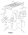
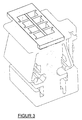
- FIG. 1 shows a connector 1, which in the other two figures 2 and 3 another perspective is shown.
- the figures show the connector 1 in his Initial state, in particular in such a state in which the connector comes from an injection molding machine.
- This connector 1 has a made of plastic base body 2, the plurality of openings 3 and 4 has, wherein the openings 3 and the openings 4 each arranged in a row and a series of openings 3 parallel to a series of openings 4 is arranged.
- the number of openings 3 and 4 is only an example and not binding.
- On the body are, in each case a series of openings 3 and 4 assigned, locking flaps 5 and 6 are arranged. These locking flaps 5 and 6 are hinges 7 and 8, in particular film hinges on the Basic body 2 arranged.
- the connector in the plastic injection molding manufactured consists of the main body 2 with the sharpened locking flaps 5 and 6 from one part.
- the locking flaps are in their pre-locked position shown.
- the locking flaps 5 and 6 each latch hooks 9 and 10, wherein the latch hooks 9 and 10th over one or more sections or over the entire width of the respective locking flap 5 and 6 can extend.
- the base body 2 has projections 11 and 12 on, behind the latching hooks 9 and 10 engage and the locking flaps 5 and 6 in their Bring detent position.
- Locking means such as webs or the like are introduced into the openings 3 and 4 Head fixed in position in the base body 2.
- the locking hooks 9 and 10 Alternatively, only the locking of the inserted conductors in the body 2 serve.
- the latching hooks 9 and 10 are in turn then not by the webs 11 and 12 clipped to the base 2, but by further, on the Base body 2 arranged locking means (see Figure 2, reference numeral 17), on this held after latching.
- This embodiment is shown in the figures.
- the locking means 17 are present on both sides of the base body 2 and extend partially or completely across the width of the body 2.
- locking flaps 5 and 6 Independent of the location and arrangement of the locking flaps 5 and 6 are locking means 13 on the Base body 2 arranged in a region corresponding to the region of the openings 3 and 4 is turned away. This area is located approximately in the middle or side, the the openings 3 and 4 faces away.
- These locking means can directly with production of the main body 2 are arranged on this, or attached later become.
- a particular advantage is in the simultaneous production of To see basic body 2 with locking means 13, since thus on the one hand simplifies the production and on the other hand, due to the material properties of the used Plastic a resilient compliance locking means 13 is realized.
- the locking means 13 a Projection 14 which is formed approximately ramp-shaped.
- the insertion of the connector is ensured, the Projection 14 in a corresponding recess in the part that the connector 1 after insertion surrounds, engages. Due to the yielding material properties can after inserting the connector 1 and pressing the Locking means 13 of these are removed from its inserted state again.
- the locking means 13, for example, a nose 15, manually or with a tool is actuated. If pressed on this nose 15, leaves the projection 14, the corresponding recess, so that the connector 1 off its inserted state can be removed.
- the base body 2 has the locking flap 5, in the area of the Detent means 13 are located, an at least the size of the locking means 13 corresponding Recess 16 on.
- This recess 16 may, depending on how far the locking means 13 are removed from the locking flap 5 in its pre-locked position, also omitted. While shown in Figure 1, that the locking means 13 only on one side are arranged of the connector 1, they can also in accordance with the Area of the opposite locking flap 6 again be present. On consideration of Figure 1 it is clear that by the arrangement of the locking means 13 of the Area in which the openings 3 and 4 are not affected, so that the Space in which the openings are 3 and 4, optimally and fully utilized can be. This can be compared to DE 199 46 470 C1, the number of contacts be increased with the same functionality of the connector 1.
Landscapes
- Multi-Conductor Connections (AREA)
- Connector Housings Or Holding Contact Members (AREA)
- Details Of Connecting Devices For Male And Female Coupling (AREA)
Abstract
Description
Claims (5)
- Steckverbinder (1) mit einem Grundkörper (2), der wenigstens eine Öffnung (3), (4) zur Aufnahme eines Leiters aufweist, wobei zumindest eine Arretierklappe (5), (6) an dem Grundkörper (2) zur Lagefixierung des zumindest einen Leiters in dem Grundkörper (2) angeordnet ist und weiterhin Rastmittel zur Lagefixierung des Steckverbinders (1) im eingesteckten Zustand vorgesehen sind, dadurch gekennzeichnet, daß die Rastmittel (13) in einem den Öffnungen (3), (4) abgewandten Bereich an den Grundkörpern (2) angeordnet sind.
- Steckverbinder (1) nach Anspruch 1, dadurch gekennzeichnet, daß mehrere Öffnungen in (3), (4) in einer Reihe angeordnet sind und jeder Reihe zumindest eine, insbesondere über die gesamte Breite der Reihe nur eine Arretierklappe (5), (6) zugeordnet ist.
- Steckverbinder (1) nach Anspruch 1 oder 2, dadurch gekennzeichnet, daß die Rastmittel (13) federnd an dem Grundkörper (2) angeordnet sind.
- Steckverbinder (1) nach einem der Ansprüche 1-3, dadurch gekennzeichnet, daß die Rastmittel (13) im Bereich der zumindest einen Arretierklappe (5), (6) angeordnet sind.
- Steckverbinder (1) nach einem der vorgehenden Ansprüche, dadurch gekennzeichnet, das die Arretierklappe (5), (6) im Bereich der Rastmittel (13) eine zumindest der Größe der Rastmittel (13) entsprechende Ausnehmung (16) aufweist.
Applications Claiming Priority (2)
| Application Number | Priority Date | Filing Date | Title |
|---|---|---|---|
| DE10157564 | 2001-11-23 | ||
| DE10157564A DE10157564A1 (de) | 2001-11-23 | 2001-11-23 | Steckverbinder |
Publications (3)
| Publication Number | Publication Date |
|---|---|
| EP1315246A2 true EP1315246A2 (de) | 2003-05-28 |
| EP1315246A3 EP1315246A3 (de) | 2004-06-23 |
| EP1315246B1 EP1315246B1 (de) | 2015-09-30 |
Family
ID=7706758
Family Applications (1)
| Application Number | Title | Priority Date | Filing Date |
|---|---|---|---|
| EP02023764.0A Expired - Lifetime EP1315246B1 (de) | 2001-11-23 | 2002-10-24 | Steckverbinder |
Country Status (3)
| Country | Link |
|---|---|
| EP (1) | EP1315246B1 (de) |
| DE (1) | DE10157564A1 (de) |
| ES (1) | ES2558977T3 (de) |
Cited By (1)
| Publication number | Priority date | Publication date | Assignee | Title |
|---|---|---|---|---|
| EP3665747A1 (de) * | 2017-08-09 | 2020-06-17 | TE Connectivity Germany GmbH | Steckergehäuse für einen elektrischen anschluss |
Families Citing this family (1)
| Publication number | Priority date | Publication date | Assignee | Title |
|---|---|---|---|---|
| EP3925033A1 (de) | 2019-02-15 | 2021-12-22 | Hirschmann Automotive GmbH | Steckverbinder mit verbessertem schutz gegenüber hochspannungsüberschlägen |
Family Cites Families (6)
| Publication number | Priority date | Publication date | Assignee | Title |
|---|---|---|---|---|
| US4017141A (en) * | 1973-05-23 | 1977-04-12 | Bury Allen J | Connectors with primary and secondary lock structure |
| MY106565A (en) * | 1991-04-09 | 1995-06-30 | Molex Inc | Electrical power connector. |
| JP3150863B2 (ja) * | 1994-11-04 | 2001-03-26 | 矢崎総業株式会社 | リヤホルダ一体型コネクタ |
| EP0933835B1 (de) * | 1998-02-03 | 2003-09-10 | The Whitaker Corporation | Steckverbinder |
| FR2784510B1 (fr) * | 1998-10-13 | 2000-11-10 | Cinch Connecteurs Sa | Connecteur electrique |
| DE19946470C1 (de) * | 1999-09-28 | 2001-05-31 | Tyco Electronics Logistics Ag | Steckverbinder mit Arretierklappe |
-
2001
- 2001-11-23 DE DE10157564A patent/DE10157564A1/de not_active Ceased
-
2002
- 2002-10-24 EP EP02023764.0A patent/EP1315246B1/de not_active Expired - Lifetime
- 2002-10-24 ES ES02023764.0T patent/ES2558977T3/es not_active Expired - Lifetime
Cited By (2)
| Publication number | Priority date | Publication date | Assignee | Title |
|---|---|---|---|---|
| EP3665747A1 (de) * | 2017-08-09 | 2020-06-17 | TE Connectivity Germany GmbH | Steckergehäuse für einen elektrischen anschluss |
| EP3665747B1 (de) * | 2017-08-09 | 2026-03-25 | TE Connectivity Germany GmbH | Steckergehäuse für einen elektrischen anschluss |
Also Published As
| Publication number | Publication date |
|---|---|
| EP1315246B1 (de) | 2015-09-30 |
| ES2558977T3 (es) | 2016-02-09 |
| EP1315246A3 (de) | 2004-06-23 |
| DE10157564A1 (de) | 2003-06-12 |
Similar Documents
| Publication | Publication Date | Title |
|---|---|---|
| EP1801927B1 (de) | Halterahmen für Steckermodule | |
| DE69508569T2 (de) | Sekundär anschluss verriegelungs element | |
| WO2021105280A1 (de) | Federkraftklemme für leiter | |
| DE2752117C2 (de) | Elektrisches Verbindergehäuse | |
| DE4131768B4 (de) | Elektrischer Verbinder mit Doppelverriegelung | |
| DE102016122238A1 (de) | Federklemmkontakt zur Kontaktierung elektrischer Leiter, Leiteranschlussklemme und Verfahren zur Herstellung eines Federklemmkontakts | |
| EP3284139B1 (de) | Federklemme | |
| DE60027520T2 (de) | Verbinder | |
| DE2819868C2 (de) | Elektrischer Verbinder | |
| EP1655813A1 (de) | Befestigung für elektrische Verbindung | |
| DE3231484A1 (de) | Elektrisches kontaktelement zur herstellung eines elektrischen kontaktes mit einem abgeflachten kontaktorgan | |
| DE102017109899A1 (de) | Elektrischer Verbinder | |
| DE102021129010A1 (de) | Kontaktträgereinrichtung, Anschlussvorrichtung, Betätiger, Steckverbindereinsatz und Montageverfahren sowie Kabelanschlusssystem | |
| DE202007009193U1 (de) | Elektrischer Steckverbinder mit Schenkelfederklemme | |
| DE3103455C2 (de) | Elektrischer Steckverbinder, insbesondere der Datentechnik | |
| EP1315246B1 (de) | Steckverbinder | |
| DE69017929T2 (de) | Verbinderhalter. | |
| DE10212511B4 (de) | Querverbinder für Reihenklemmen | |
| DE602004007447T2 (de) | Elektrisches Gerät mit einem isolierten Gehäuse und einer in dem Gehäuse angeordneten automatischen Anschlussklemme | |
| DE102012103399A1 (de) | Baugruppe für einen elektrischen Steckverbinder und Bausatz | |
| DE102017213105A1 (de) | Elektrisches Kontaktgehäuse zur vereinfachten Kontaktassemblage | |
| DE19638972B4 (de) | Sicherungsleiste | |
| EP3754845A1 (de) | Vorrichtung zum absorbieren des elektrischen rauschens | |
| DE19652855C1 (de) | Elektrischer Steckverbinder | |
| DE3400935C2 (de) |
Legal Events
| Date | Code | Title | Description |
|---|---|---|---|
| PUAI | Public reference made under article 153(3) epc to a published international application that has entered the european phase |
Free format text: ORIGINAL CODE: 0009012 |
|
| AK | Designated contracting states |
Designated state(s): AT BE BG CH CY CZ DE DK EE ES FI FR GB GR IE IT LI LU MC NL PT SE SK TR |
|
| AX | Request for extension of the european patent |
Extension state: AL LT LV MK RO SI |
|
| PUAL | Search report despatched |
Free format text: ORIGINAL CODE: 0009013 |
|
| AK | Designated contracting states |
Kind code of ref document: A3 Designated state(s): AT BE BG CH CY CZ DE DK EE ES FI FR GB GR IE IT LI LU MC NL PT SE SK TR |
|
| AX | Request for extension of the european patent |
Extension state: AL LT LV MK RO SI |
|
| RIC1 | Information provided on ipc code assigned before grant |
Ipc: 7H 01R 13/436 A Ipc: 7H 01R 13/627 B |
|
| RAP1 | Party data changed (applicant data changed or rights of an application transferred) |
Owner name: HIRSCHMANN AUTOMOTIVE GMBH |
|
| 17P | Request for examination filed |
Effective date: 20041104 |
|
| 17Q | First examination report despatched |
Effective date: 20050124 |
|
| AKX | Designation fees paid |
Designated state(s): AT BE BG CH CY CZ DE DK EE ES FI FR GB GR IE IT LI LU MC NL PT SE SK TR |
|
| GRAP | Despatch of communication of intention to grant a patent |
Free format text: ORIGINAL CODE: EPIDOSNIGR1 |
|
| RIC1 | Information provided on ipc code assigned before grant |
Ipc: H01R 13/627 20060101ALI20150617BHEP Ipc: H01R 13/50 20060101ALN20150617BHEP Ipc: H01R 13/436 20060101AFI20150617BHEP Ipc: H01R 43/18 20060101ALN20150617BHEP |
|
| INTG | Intention to grant announced |
Effective date: 20150707 |
|
| GRAS | Grant fee paid |
Free format text: ORIGINAL CODE: EPIDOSNIGR3 |
|
| GRAA | (expected) grant |
Free format text: ORIGINAL CODE: 0009210 |
|
| AK | Designated contracting states |
Kind code of ref document: B1 Designated state(s): AT BE BG CH CY CZ DE DK EE ES FI FR GB GR IE IT LI LU MC NL PT SE SK TR |
|
| REG | Reference to a national code |
Ref country code: CH Ref legal event code: EP Ref country code: GB Ref legal event code: FG4D Free format text: NOT ENGLISH |
|
| REG | Reference to a national code |
Ref country code: AT Ref legal event code: REF Ref document number: 752932 Country of ref document: AT Kind code of ref document: T Effective date: 20151015 |
|
| REG | Reference to a national code |
Ref country code: IE Ref legal event code: FG4D Free format text: LANGUAGE OF EP DOCUMENT: GERMAN |
|
| REG | Reference to a national code |
Ref country code: FR Ref legal event code: PLFP Year of fee payment: 14 |
|
| REG | Reference to a national code |
Ref country code: DE Ref legal event code: R096 Ref document number: 50216091 Country of ref document: DE |
|
| PG25 | Lapsed in a contracting state [announced via postgrant information from national office to epo] |
Ref country code: GR Free format text: LAPSE BECAUSE OF FAILURE TO SUBMIT A TRANSLATION OF THE DESCRIPTION OR TO PAY THE FEE WITHIN THE PRESCRIBED TIME-LIMIT Effective date: 20151231 Ref country code: FI Free format text: LAPSE BECAUSE OF FAILURE TO SUBMIT A TRANSLATION OF THE DESCRIPTION OR TO PAY THE FEE WITHIN THE PRESCRIBED TIME-LIMIT Effective date: 20150930 |
|
| REG | Reference to a national code |
Ref country code: NL Ref legal event code: MP Effective date: 20150930 |
|
| REG | Reference to a national code |
Ref country code: ES Ref legal event code: FG2A Ref document number: 2558977 Country of ref document: ES Kind code of ref document: T3 Effective date: 20160209 |
|
| PG25 | Lapsed in a contracting state [announced via postgrant information from national office to epo] |
Ref country code: SE Free format text: LAPSE BECAUSE OF FAILURE TO SUBMIT A TRANSLATION OF THE DESCRIPTION OR TO PAY THE FEE WITHIN THE PRESCRIBED TIME-LIMIT Effective date: 20150930 |
|
| PG25 | Lapsed in a contracting state [announced via postgrant information from national office to epo] |
Ref country code: NL Free format text: LAPSE BECAUSE OF FAILURE TO SUBMIT A TRANSLATION OF THE DESCRIPTION OR TO PAY THE FEE WITHIN THE PRESCRIBED TIME-LIMIT Effective date: 20150930 Ref country code: SK Free format text: LAPSE BECAUSE OF FAILURE TO SUBMIT A TRANSLATION OF THE DESCRIPTION OR TO PAY THE FEE WITHIN THE PRESCRIBED TIME-LIMIT Effective date: 20150930 Ref country code: EE Free format text: LAPSE BECAUSE OF FAILURE TO SUBMIT A TRANSLATION OF THE DESCRIPTION OR TO PAY THE FEE WITHIN THE PRESCRIBED TIME-LIMIT Effective date: 20150930 |
|
| PG25 | Lapsed in a contracting state [announced via postgrant information from national office to epo] |
Ref country code: PT Free format text: LAPSE BECAUSE OF FAILURE TO SUBMIT A TRANSLATION OF THE DESCRIPTION OR TO PAY THE FEE WITHIN THE PRESCRIBED TIME-LIMIT Effective date: 20160201 |
|
| REG | Reference to a national code |
Ref country code: CH Ref legal event code: PL |
|
| PG25 | Lapsed in a contracting state [announced via postgrant information from national office to epo] |
Ref country code: MC Free format text: LAPSE BECAUSE OF FAILURE TO SUBMIT A TRANSLATION OF THE DESCRIPTION OR TO PAY THE FEE WITHIN THE PRESCRIBED TIME-LIMIT Effective date: 20150930 |
|
| REG | Reference to a national code |
Ref country code: DE Ref legal event code: R097 Ref document number: 50216091 Country of ref document: DE |
|
| REG | Reference to a national code |
Ref country code: IE Ref legal event code: MM4A |
|
| PG25 | Lapsed in a contracting state [announced via postgrant information from national office to epo] |
Ref country code: LI Free format text: LAPSE BECAUSE OF NON-PAYMENT OF DUE FEES Effective date: 20151031 Ref country code: CH Free format text: LAPSE BECAUSE OF NON-PAYMENT OF DUE FEES Effective date: 20151031 |
|
| PLBE | No opposition filed within time limit |
Free format text: ORIGINAL CODE: 0009261 |
|
| STAA | Information on the status of an ep patent application or granted ep patent |
Free format text: STATUS: NO OPPOSITION FILED WITHIN TIME LIMIT |
|
| PG25 | Lapsed in a contracting state [announced via postgrant information from national office to epo] |
Ref country code: DK Free format text: LAPSE BECAUSE OF FAILURE TO SUBMIT A TRANSLATION OF THE DESCRIPTION OR TO PAY THE FEE WITHIN THE PRESCRIBED TIME-LIMIT Effective date: 20150930 |
|
| 26N | No opposition filed |
Effective date: 20160701 |
|
| REG | Reference to a national code |
Ref country code: FR Ref legal event code: PLFP Year of fee payment: 15 |
|
| PG25 | Lapsed in a contracting state [announced via postgrant information from national office to epo] |
Ref country code: IE Free format text: LAPSE BECAUSE OF NON-PAYMENT OF DUE FEES Effective date: 20151024 |
|
| REG | Reference to a national code |
Ref country code: AT Ref legal event code: MM01 Ref document number: 752932 Country of ref document: AT Kind code of ref document: T Effective date: 20151024 |
|
| PG25 | Lapsed in a contracting state [announced via postgrant information from national office to epo] |
Ref country code: AT Free format text: LAPSE BECAUSE OF NON-PAYMENT OF DUE FEES Effective date: 20151024 |
|
| PG25 | Lapsed in a contracting state [announced via postgrant information from national office to epo] |
Ref country code: BG Free format text: LAPSE BECAUSE OF FAILURE TO SUBMIT A TRANSLATION OF THE DESCRIPTION OR TO PAY THE FEE WITHIN THE PRESCRIBED TIME-LIMIT Effective date: 20150930 |
|
| PG25 | Lapsed in a contracting state [announced via postgrant information from national office to epo] |
Ref country code: CY Free format text: LAPSE BECAUSE OF FAILURE TO SUBMIT A TRANSLATION OF THE DESCRIPTION OR TO PAY THE FEE WITHIN THE PRESCRIBED TIME-LIMIT Effective date: 20150930 |
|
| PG25 | Lapsed in a contracting state [announced via postgrant information from national office to epo] |
Ref country code: BE Free format text: LAPSE BECAUSE OF NON-PAYMENT OF DUE FEES Effective date: 20151031 |
|
| PG25 | Lapsed in a contracting state [announced via postgrant information from national office to epo] |
Ref country code: TR Free format text: LAPSE BECAUSE OF FAILURE TO SUBMIT A TRANSLATION OF THE DESCRIPTION OR TO PAY THE FEE WITHIN THE PRESCRIBED TIME-LIMIT Effective date: 20150930 |
|
| REG | Reference to a national code |
Ref country code: FR Ref legal event code: PLFP Year of fee payment: 16 |
|
| PG25 | Lapsed in a contracting state [announced via postgrant information from national office to epo] |
Ref country code: LU Free format text: LAPSE BECAUSE OF NON-PAYMENT OF DUE FEES Effective date: 20151024 |
|
| REG | Reference to a national code |
Ref country code: FR Ref legal event code: PLFP Year of fee payment: 17 |
|
| PGFP | Annual fee paid to national office [announced via postgrant information from national office to epo] |
Ref country code: CZ Payment date: 20211025 Year of fee payment: 20 Ref country code: DE Payment date: 20211020 Year of fee payment: 20 Ref country code: ES Payment date: 20211223 Year of fee payment: 20 Ref country code: GB Payment date: 20211022 Year of fee payment: 20 |
|
| PGFP | Annual fee paid to national office [announced via postgrant information from national office to epo] |
Ref country code: IT Payment date: 20211028 Year of fee payment: 20 Ref country code: FR Payment date: 20211021 Year of fee payment: 20 |
|
| REG | Reference to a national code |
Ref country code: DE Ref legal event code: R071 Ref document number: 50216091 Country of ref document: DE |
|
| REG | Reference to a national code |
Ref country code: ES Ref legal event code: FD2A Effective date: 20221031 |
|
| REG | Reference to a national code |
Ref country code: GB Ref legal event code: PE20 Expiry date: 20221023 |
|
| PG25 | Lapsed in a contracting state [announced via postgrant information from national office to epo] |
Ref country code: GB Free format text: LAPSE BECAUSE OF EXPIRATION OF PROTECTION Effective date: 20221023 Ref country code: ES Free format text: LAPSE BECAUSE OF EXPIRATION OF PROTECTION Effective date: 20221025 Ref country code: CZ Free format text: LAPSE BECAUSE OF EXPIRATION OF PROTECTION Effective date: 20221024 |