EP1314518B1 - Outil portatif motorisé avec poignée et carter pivotant - Google Patents
Outil portatif motorisé avec poignée et carter pivotant Download PDFInfo
- Publication number
- EP1314518B1 EP1314518B1 EP02024800A EP02024800A EP1314518B1 EP 1314518 B1 EP1314518 B1 EP 1314518B1 EP 02024800 A EP02024800 A EP 02024800A EP 02024800 A EP02024800 A EP 02024800A EP 1314518 B1 EP1314518 B1 EP 1314518B1
- Authority
- EP
- European Patent Office
- Prior art keywords
- handle
- tool
- power tool
- tool body
- axis
- Prior art date
- Legal status (The legal status is an assumption and is not a legal conclusion. Google has not performed a legal analysis and makes no representation as to the accuracy of the status listed.)
- Expired - Lifetime
Links
- 230000033001 locomotion Effects 0.000 claims abstract description 17
- 230000008878 coupling Effects 0.000 description 6
- 238000010168 coupling process Methods 0.000 description 6
- 238000005859 coupling reaction Methods 0.000 description 6
- 239000002184 metal Substances 0.000 description 5
- 238000005553 drilling Methods 0.000 description 2
- 230000000007 visual effect Effects 0.000 description 2
- 235000013290 Sagittaria latifolia Nutrition 0.000 description 1
- 229910000831 Steel Inorganic materials 0.000 description 1
- 230000005540 biological transmission Effects 0.000 description 1
- 235000015246 common arrowhead Nutrition 0.000 description 1
- 230000001419 dependent effect Effects 0.000 description 1
- 230000000994 depressogenic effect Effects 0.000 description 1
- 239000000428 dust Substances 0.000 description 1
- 230000001788 irregular Effects 0.000 description 1
- 239000000463 material Substances 0.000 description 1
- 239000010959 steel Substances 0.000 description 1
Images


Classifications
-
- B—PERFORMING OPERATIONS; TRANSPORTING
- B25—HAND TOOLS; PORTABLE POWER-DRIVEN TOOLS; MANIPULATORS
- B25F—COMBINATION OR MULTI-PURPOSE TOOLS NOT OTHERWISE PROVIDED FOR; DETAILS OR COMPONENTS OF PORTABLE POWER-DRIVEN TOOLS NOT PARTICULARLY RELATED TO THE OPERATIONS PERFORMED AND NOT OTHERWISE PROVIDED FOR
- B25F5/00—Details or components of portable power-driven tools not particularly related to the operations performed and not otherwise provided for
- B25F5/02—Construction of casings, bodies or handles
-
- Y—GENERAL TAGGING OF NEW TECHNOLOGICAL DEVELOPMENTS; GENERAL TAGGING OF CROSS-SECTIONAL TECHNOLOGIES SPANNING OVER SEVERAL SECTIONS OF THE IPC; TECHNICAL SUBJECTS COVERED BY FORMER USPC CROSS-REFERENCE ART COLLECTIONS [XRACs] AND DIGESTS
- Y10—TECHNICAL SUBJECTS COVERED BY FORMER USPC
- Y10T—TECHNICAL SUBJECTS COVERED BY FORMER US CLASSIFICATION
- Y10T408/00—Cutting by use of rotating axially moving tool
- Y10T408/91—Machine frame
Definitions
- the present invention relates to power tools and, in particular, to improved electric drills comprising a handle and a pivotable drill head with an improved pivotal angle between the drill head and the handle.
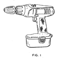
- FIG. 1 This drill-driver comprises a body having a drill head portion and a handle portion fixed at approximately right-angle to the drill head portion.
- the drill head portion encapsulates an electric motor and a gearbox and the handle portion defines a conventional pistol grip to be grasped by the user.
- the handle portion comprises a variable speed trigger switch for low-speed rotary output in screw driving mode or high-speed rotary output in drilling mode.
- This drill-driver is well suited to drilling and screw driving, provided that the workpiece is easily accessible. However, if the hole to be drilled, or the screw to be fastened, is in a tight comer or an awkward position then this drill-driver, like a conventional electric drill, cannot gain access. In this case the user will need to resort to a smaller hand operated drill or a hand held screwdriver perform the task in hand.
- German Utility Model 8505814.9 discloses an electric drill having a drill head and a handle.
- the drill head comprises an electric motor coupled to a gearbox.
- the gearbox includes a rotary output protruding from the front end of the drill head.
- the handle comprises an on/off trigger switch and a battery pack.
- a flange extension attached to the rear end of the drill head is pivotally coupled to the top end of the handle.
- the drill head can be pivotally adjusted with respect to the handle through an arc of 90°, between a position where the drill head is perpendicular to the handle and another position where the drill head is in-line with the handle.
- the radial length of the pivotal arc described by the pivoting tool head is equal to the length of the tool body plus the distance of the pivot point of the flange extension from the rear end of the drill head.
- US5149230 describes a power tool comprising a handle portion a drill head assembly having two chucks and a safety guard.
- the drill head assembly is rotatable about an axis defined by the handle assembly.
- the tool body is elongate with a longitudinal axis parallel to the first axis and the power tool further comprises a motor coupled to a rotary output, wherein the rotary output has the first axis.
- the rotary output conveniently protrudes from one of the ends of the elongate tool body.
- the motor is housed in the tool body, rather than the handle. This avoids the need for a complex mechanical coupling between the motor located in the handle and the rotary output located in the tool body.
- the elongate tool body has a front end and a rear end and the pivot is located between the front and rear ends of the tool body so that the radial length of the pivotal arc described by the pivoting tool head may be equal to the length of the tool body, or less.
- the pivot be located in the space between the ends of the tool body.
- the pivot need not be located upon the tool head itself and could instead be located on a flange attached to the tool head, provided this flange is located in the space between the ends of the tool body.
- the pivot is located in the middle region of the tool body.
- the middle region of the tool body is the space located between 20% and 80% of the length of the elongate tool body, as measured form one end.
- the radial length of the pivotal arc may be reduced to less than 81% of the length of the tool body thereby allowing the power tool to operate in smaller areas.
- the radial length of the pivotal arc would be equivalent to the length of the tool head plus the distance of the pivot from the tool head. This addition to the radial length of the pivotal arc would unnecessarily prohibit such a power tool from operating in small areas which would be otherwise accessible to a power tool with the pivot located between the ends of the tool body.
- the second axis may intersect the tool body, thus ensuring that the pivot is located upon the tool body.
- the pivot and the second axis may intersect the midpoint of the length of the tool body thereby reducing the radial length of the pivotal arc to only 50% of the length of tool head.
- the pivotal angle can vary within a range of 180° thus providing another operating position, in addition to those described above, wherein:
- orientation of the drill head relative to the handle need not be limited to operating positions i), ii) and iii) above when pivoting over a pivotal angle range of 180°, or any other pivotal angle range, and may also include one or more other positions.
- the pivotal angle may vary between 90° and 270° such that the tool head is perpendicular to the handle in positions i) and iii) above.
- the at least one aperture is formed in the handle and the at least one hub is disposed upon the tool body.
- the number of holes in the tool body is reduced. This reduces the locations where dust and dirt may enter the interior of the tool body and interfere with the components, such as the motor, enclosed therein. Minimising the number of holes formed in the tool body has the advantage of increasing shielding of the interior components.
- the power tool preferably comprises a locking mechanism for locking the tool body against pivotal movement relative to the handle.
- the locking mechanism can be released to allow pivotal movement of the tool head relative to the handle when the user wishes to change the orientation of the tool head in preparation for a different task. After changing the orientation of the tool head, the user can lock the tool body in its new position by operating the locking mechanism.
- many different and suitable types of locking mechanism are readily available like, for example, a simple nut and bolt arrangement or a magnetic lock.
- the preferred locking mechanism comprises a locking plate disposed upon one of the tool body or handle, the locking plate being moveable between a locked position and an unlocked position, wherein the locking plate is engaged with the other of the tool body or handle when in the locked position thereby preventing pivotal movement of the tool body relative to the handle and wherein the locking plate is disengaged with the other of the tool body or handle when in the unlocked position thereby permitting pivotal movement of the tool body relative to the handle.
- the locking plate may be resiliently biased into the locking position.
- the tool body is automatically prohibited from pivoting relative to the handle unless the locking mechanism is deliberately operated by the user. This leaves both the user's hands free to undertake the task.
- the locking plate is resiliently biased by a spring.
- the spring may be a leaf spring, a coil spring or a helical spring.
- a helical spring is the preferred type of spring because it is readily available, compact, durable and inexpensive and, as such, is ideally suited for the task of biasing the locking plate into the locked position.
- the locking plate has a protrusion for locking engagement with one of a plurality of recesses disposed upon the other of the tool body or handle.
- the location of each one of the plurality of recesses pre-determines the choice of orientations that can be adopted by the tool body relative to the handle.
- Each additional recess corresponds to an additional orientation of the tool body relative to the handle.
- the locking plate may slide between the locked position and the unlocked position. Sliding movement of the locking plate can be guided part of one of the tool body or handle.
- the locking plate may be operable by a release button fixed to the locking plate.
- the locking plate is disposed adjacent one of the second hub or the second aperture and the plurality of recesses is disposed around the circumference of the other of the second hub or the second aperture.
- each one of the plurality of recesses is disposed at equi-angular intervals around the circumference of the other of the second hub or the second aperture.
- the plurality of recesses may be disposed upon the second hub.
- the electrical connection between the switch and the motor may be by electrical wire, or by metal strips with metal slip rings located at the pivot.
- the electrical connection comprises two electrical wires. More preferably the connection aperture in the first hub is concentric with the second axis. Electrical wires have the advantage of being more flexible than metal strips and therefore less liable to breakage, and are insulated. Additionally, the connection aperture being concentric with the second axis (i.e. at the centre of the first hub) has the advantage that the wires are only lithtly twisted as the tool head pivots relative to the handle and, as such, the wires are not subject to significant wear and tear. Using wires to electrically couple the power source with the motor obviates the need to implement the more complex solution of using metal strips with metal slip rings at the pivot.
- the power source is preferably a battery pack.
- the battery pack may be housed within the handle or detachably connected to the handle.
- a battery pack housed within the handle may be electrically coupled to an electrical socket disposed upon the handle.
- the electrical socket connects the battery pack to an external battery charging source.
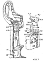
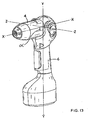
- a power tool shown generally as (2) is a drill-driver comprising a substantially cylindrical drill head (4) having a longitudinal axis X and an elongate handle (6) arranged about a longitudinal axis Y.
- the drill head (4) is pivotally mounted upon the handle (6) and pivots relative to the handle (6) about an axis Z.
- the handle (6) is formed by a first clamshell (8) and a second clamshell (10) which are joined together by a plurality of screws (not shown).
- the drill head (4) is formed by a third clamshell (12) and a fourth clamshell (14) which are joined together by a plurality of screws (not shown).
- the drill head (4) comprises an electric motor (16) and a transmission gearbox (not shown) with an output spindle (20).
- the motor (16) and the gearbox are housed inside the drill head (4).
- the front end of the drill head (4) comprises a cylindrical gear casing (22) surrounding the gearbox and the output spindle (20).
- the motor (16) is rotatingly coupled to the gearbox such that rotary motion of the motor (16) is transferred to the output spindle (20) via the gearbox.
- the end portion of the output spindle (20) has a hex drive coupling (24) attached thereto.
- the output spindle (20) and the coupling (24) protrude through a hole (26) in the gear casing (22).
- the output spindle (20) and the coupling (24) rotate about the axis (x).
- the coupling (24) releasably connects the output spindle (20) to a tool (28) having a conventional hexagonal shank arrangement.
- a conventional chuck can be attached to the end portion of the output spindle (20) for connection to a tool (28).
- the handle (6) comprises a button (30) fixed to a variable speed electrical switch (32).
- the switch (32) is electrically coupled to a power source (34).
- the switch (32) is also electrically coupled to the motor (16) by two electrical wires (36,38).
- the switch (32) is thermally coupled to a heat sink (39) located inside the handle (6).
- the heat sink (39) is for dissipating excess heat energy created by the internal components of the switch (32).
- the switch (32) is biased into an OFF position wherein the switch (32) interrupts electrical connection between the power source (38) and the motor (16) such that the motor (16) is denergised and the output spindle (20) does not rotate.
- Depression of the button (30) moves the switch (32) to an ON position wherein the switch (32) makes electrical connection between the power source (34) and the motor (16).
- the motor (20) is energised by the electrical current from the power source (34) and the output spindle (20) starts to rotate. Electrical current flowing from the power source (34) to the motor (16) is thus controlled by the switch (32) and is proportional to how far the button (30) is depressed.
- the switch (32) increases so does flow of electrical current to the motor (16) causing a corresponding increase in the rotational speed of the output spindle (20), and vice versa.
- the switch (32) returns to the OFF position to interrupt the electrical connection between the power source (34) and the motor (16) thus causing denergision of the motor (16).
- the handle (6) comprises a direction selector (40) for selecting the rotational direction of the motor (16) and the output spindle (20).
- the direction selector (40) is approximately T-shaped and comprises a forward button (42) on one side, a reverse button (44) on the other side, and a flange (46) in the middle.
- the forward (42) and reverse (44) buttons partially protrude through an aperture in each of the first (8) and second (10) clamshells respectively.
- the handle also comprises a barrel (48) with an upper flange (50), a lower flange (52) and a central cylinder (54) located between the upper and lower flanges (52,54).
- the barrel's flanges (50,52) each have a mainly circular circumference part which is interrupted by a protruding part and are shaped like a tear-drop.
- the circular part of upper and lower flanges (50,52) has a diameter greater than the central cylinder (54).
- the protruding part of the upper flange (50) has an upper spigot (56).
- the protruding part of the lower flange (54) has a lower spigot (58).
- the upper and lower spigots (56,58) are eccentric with respect the axis of the central cylinder (54) and point axially away from the central cylinder (54).
- the barrel (48) is supported for pivotal rotation by a pair of brackets (60,62) which are moulded into interior of the handle's clamshells (8,10).
- the brackets (60,62) surround the central cylinder (54) to support the barrel (48) against lateral movement.
- the brackets (60,62) abut the inner faces of the upper and lower flanges (50,52) to support the barrel (48) against axial movement.
- the handle (6) further comprises an arm (64) with a hollow cylindrical hub (66) at one end and a finger (68) at the other end.
- the arm (64) is pivotally coupled to the internal components of the switch (32) at a point midway between the hub (66) and the finger (68).
- the arm (64) can pivot between a forward position, a central position and a reverse position. Pivotal movement of the arm (64) from its forward position to its reverse position, arid vice versa, causes the switch (32) to change the polarity of the electrical wires (36,38), as explained in more detail below.
- the direction selector (40) is mechanically coupled to the switch (32) via the barrel (48) and the arm (64) in the following manner.
- the barrel's upper spigot (56) engages the direction selector (40) by protruding through a hole in the flange (46).
- the barrel's lower spigot (58) is seated within the arm's hollow cylindrical hub (66) in the manner of a trunnion arrangement.
- depression of the forward button (42) slides the direction selector (40) and the upper spigot (56) in one direction thereby rotating the barrel (48) about its axis.
- Rotation of the barrel (48) moves the lower spigot (58) in the opposite direction thereby pivoting the arm (64) into its forward position.
- Depression of the reverse button (44) reverses this sequence and causes the arm (64) to pivot from its forward position to its reverse position.
- the direction selector's buttons (42,44) are arrow-head shaped.
- the apex of the forward button (42) points forward to give the user a visual and tangible indication that depression of the forward button (42) causes the output spindle (20) to rotate in a clockwise direction (i.e. the rotational direction causing a screw or drill bit to be driven "forward" into a work piece) when the switch (32) is in the ON position.
- the apex of the reverse button (44) points backward to give the user a visual and tangible indication that depression of the reverse button (42) causes the output spindle (20) to rotate in an anti-clockwise direction when the switch (32) is in the ON position.
- the power source is a rechargeable battery pack (34) housed inside the bottom of the handle (6). To improve the electrical charge of the battery pack (34), thereby increasing operating life, the battery pack (34) is relatively bulky causing the handle (6) to protrude on the side of the switch button (30).
- the battery pack (34) is electrically coupled to a battery recharger socket (72) located at the lower end of the handle (6).
- the battery recharger socket (72) protrudes through a small aperture (74) in the handle (6) to provide an electrical link between the battery pack (34) and an external battery recharging source (not shown).
- the power source may be a rechargeable battery detachably fixed to the handle (6), or a mains electrical supply.
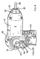
- the drill head (4) has a first cylindrical hub (76) and a second cylindrical hub (78) both located part way along the length of the drill head (4), remote from the output spindle (20).
- the first and second hubs (76,78) are located on opposite sides of the drill head (4).
- the first and second hubs (76, 78) are substantially the same diameter and both arranged about axis Z.
- the first and second hubs (76, 78) extend from the drill head (4) in diametrically opposed directions along axis Z.
- Axis Z is perpendicular to axis's X and Y.
- the first cylindrical hub (76) is moulded into the third clam shell (12) of the drill head (4).
- the first cylindrical hub (76) comprises a central inner aperture (80) co-axial with axis Z.
- the inner aperture (80) provides an entry point to the interior of the drill head (4).
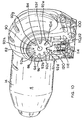
- the second hub (78) comprises a circular toothed wheel (82), a protrusion (86) and, a cylindrical spigot (84) having axis Z.
- the protrusion (86) and the spigot (84) are moulded into the fourth clam shell (14) of the drill head (4).
- the wheel (82) comprises a central aperture (88) and a plurality of teeth (90) arranged equi-angularly around the circumference of the wheel (82).
- the toothed wheel (82) has eight teeth (90) juxtaposed by eight recesses (92) for engagement with part of a locking plate, which is described in more detail below.
- the eight teeth (90) are arranged at 45° intervals about the axis Z.
- the wheel (82) is press fitted upon the fourth clam shell (14). Two of the eight teeth (90) are shorter than the outer diameter of the wheel (82).
- the protrusion (86) has a curved exterior face (94) and an interior face (96) shaped to surround the two short teeth (90) and engage three recesses (92a, 92b, 92c) adjacent the two short teeth (90) thereby preventing rotation of the wheel (82) relative to the drill head (4).
- the spigot (84) protrudes through the aperture (88).
- the outer diameter of the spigot (84) is slightly larger that the diameter of the aperture (88) such that interference fit between the spigot (84) and the circumference of the aperture (88) holds the wheel (82) upon the drill head (4).
- the curved exterior face (94) of the protrusion (86) and the tips of the teeth (90) collectively describe the outer circumference of the second hub (78).
- the wheel (82) is made of steel, Alternatively, the wheel (82) may be made of another suitable hard material.
- first supporting bracket (98) and a second supporting bracket (100) each shaped to nest in the interior of the first and the second clamshells (8,10) of the handle (6), respectively.
- the first bracket (98) has a circular aperture (102) for receiving the first hub (76).
- the second bracket (100) has a circular aperture (104) for receiving the second hub (76).
- the first and second hubs (76,78), the first and second bracket apertures (102,104), the first hub aperture (80) and the spigot (84) are co-axial having axis Z.
- the first and second bracket apertures (102,104) act as a yoke in which the first and second hubs (76,78) are supported for pivotal rotation relative to the handle (6). As such, the first and second bracket apertures (102,104) provide pivotal support to the first and second hubs (76,78), respectively, to allow the drill head (4) to pivot relative the handle (6) about axis Z.
- the first support bracket (98) has a first walled recess (106) facing the interior of the first clam shell (8) of the handle (6).
- the cavity (108) provides a connecting passageway from the interior of the handle (6) to first hub (76) for the wires (36,38). Accordingly, the wires (36,38) travel from the switch (32) via the cavity (108) through the first hub's aperture (80) to the motor (20) inside the drill head (4).
- the second support bracket (100) has a second walled recess (110) facing the interior of the first clam shell (10) of the handle (6).
- a space (112) bounded by the second walled recess (110) and the interior of the second clam shell (10) is formed therebetween.
- the space (112) contains a locking plate (114), a lock release button (116) fixed to the locking plate (114), and two helical springs (118).
- the locking plate (114) has a tongue (120) which is for locking engagement with any one of the five recesses (92d to 92h) of the toothed wheel (82) not occupied by the interior face (96) of the protrusion (86).
- the locking plate (114), the lock release button (116), and the two helical springs (118) collectively form a locking mechanism for locking pivotal movement of the head (4) relative to the handle (6) about the axis Z.
- the tongue (120) of the locking plate (114) is biased into engagement with a recess (92) by the springs (118), thereby locking pivotal movement of the head (4) relative to the handle (6).
- the user disengages the tongue (120) from a recess (92) by sliding the locking plate (114) and the release button (116) against the bias of the springs (118). Sliding movement of the locking plate (114) is guided by the second walled recess (110).
- Access to the release button (116) for operation of the locking plate (114) is provided by a hole (122) in the top end of the second clamshell (10) of the handle (6).
- axis Z is the axis about which the head (4) pivots with respect to the handle (6).
- Axis Y represents the position of the handle (6) and axis X represents the position of the drill head (4). Both axis X and Y remain perpendicular to axis Z regardless of the orientation of the drill head (4) in relation to the handle (8).
- the included angle between axis X and Y is referred to as angle ⁇ . Only angle ⁇ varies when the drill head (4) changes its orientation in relation to the handle (8) by pivoting about the axis Z.
- Angle ⁇ is dictated by which one of the five unoccupied recesses (92d to 92h) engages the tongue (120) of the locking plate (114). Angle ⁇ is 90° when recess (92d) engages the tongue (120), as shown in Figure 13 . Recess (92e) is located 45° anti-clockwise from recess (92d), therefore angle ⁇ is 135° when recess (92e) engages the tongue (120), as shown in Figure 11 . Angle ⁇ is 180°, 225° and 270° when one of the three respective subsequent recesses (92f, 92g, 92h) engage the tongue (120).
- angle ⁇ can be set to five positions within a range of 180°, according to which one of the five unoccupied recesses (92d to 92h) engages the locking plate (114).
- the range of angle ⁇ can be increased from 180° by reducing the number of recesses (92) engaged by the interior face (96) of the protrusion (86) from three recesses (92a, 92b, 92c) to two recesses, or even only one recess.
- the number of positions within the range of angle ⁇ can be varied by changing the number of recesses (92) and teeth (90), or varying the angular spacing between adjacent recesses (92) and teeth (90) around the circumference of the toothed wheel (82).
Landscapes
- Engineering & Computer Science (AREA)
- Mechanical Engineering (AREA)
- Drilling And Boring (AREA)
- Harvester Elements (AREA)
- Rotary Switch, Piano Key Switch, And Lever Switch (AREA)
- Scissors And Nippers (AREA)
- Grinding-Machine Dressing And Accessory Apparatuses (AREA)
Claims (25)
- Outil motorisé (2) comprenant :➢ une source d'alimentation électrique (34) pour mettre sous tension un moteur (16) accouplé avec une sortie rotative (20) ;➢ un commutateur électrique (32) électriquement accouplé avec la source d'alimentation électrique (34) ;➢ une connexion électrique (36, 38) pour transporter un courant électrique du commutateur (32) au moteur (16) ;➢ une poignée (6), dans lequel le commutateur électrique (32) est disposé sur la poignée (6) ; et➢ un corps d'outil (4) accouplé de façon pivotante avec la poignée (6),dans lequel le corps d'outil (4) possède un premier axe (x) et le corps d'outil (4) est accouplé de façon pivotante avec la poignée (6) par l'intermédiaire d'un pivot (76, 78, 102, 104) possédant un deuxième axe (z), dans lequel le premier axe (x) est perpendiculaire au deuxième axe (z), et dans lequel la poignée (6) est oblongue et possède un troisième axe (y), le troisième axe (y) étant perpendiculaire au deuxième axe (z) et dans lequel un arc défini par la rotation pivotante de la tête d'outil (4) par rapport à la poignée (6) sur le deuxième axe (z) sous-tend un angle de pivotement (α) entre le premier axe (x) et le troisième axe (y) ;
dans lequel le pivot (76, 78, 102, 104) comprend :➢ une première ouverture circulaire (102) et une seconde ouverture circulaire (104) formées dans un élément parmi le corps d'outil (4) ou la poignée (6), la première ouverture circulaire (102) et la seconde ouverture circulaire (104) possédant chacune le deuxième axe (z) ;➢ un premier moyeu cylindrique (76) disposé concentriquement à l'intérieur de la première ouverture (102) et un second moyeu cylindrique (78) disposé concentriquement à l'intérieur de la seconde ouverture (104) de sorte qu'un contact coulissant entre les moyeux cylindriques (76, 78) et des ouvertures circulaires respectives (102, 104) supporte la tête d'outil (4) pour une rotation pivotante par rapport à la poignée (6), dans lequel lesdits premier et second moyeux cylindriques font saillie à partir de l'autre élément parmi le corps d'outil (4) ou la poignée (6) ;caractérisé en ce que l'angle de pivotement (a) peut varier selon plus de 90° et en ce que la connexion électrique (36, 38) entre dans le corps d'outil (4) à travers une ouverture de connexion (80) dans le premier moyeu (76). - Outil motorisé (2) selon la revendication 1, dans lequel le corps d'outil (4) est oblong avec un axe longitudinal parallèle au premier axe (x) et dans lequel la sortie rotative (20) possède le premier axe (x).
- Outil motorisé (2) selon la revendication 2, dans lequel le moteur (16) est logé dans le corps d' outil (4).
- Outil motorisé (2) selon l'une quelconque des revendications 2 ou 3, dans lequel le corps d'outil oblong (4) possède une extrémité avant et une extrémité arrière et le pivot (76, 78, 102, 104) est situé entre les extrémités avant et arrière du corps d'outil (4).
- Outil motorisé (2) selon la revendication 4, dans lequel le pivot (76, 78, 102, 104) est situé dans la région médiane du corps d'outil (4).
- Outil motorisé (2) selon l'une quelconque des revendications précédentes, dans lequel le deuxième axe (z) croise le corps d'outil (4).
- Outil motorisé (2) selon l'une quelconque des revendications précédentes, dans lequel l'angle de pivotement (a) peut varier de 180°.
- Outil motorisé (2) selon l'une quelconque des revendications précédentes, dans lequel la valeur de l'angle de pivotement (a) peut varier entre 90° et 270°.
- Outil motorisé (2) selon l'une quelconque des revendications précédentes, dans lequel les ouvertures (102, 104) sont formées dans la poignée (6) et les moyeux (76, 78) sont disposés sur le corps d'outil (4).
- Outil motorisé (2) selon l'une quelconque des revendications précédentes, dans lequel l'outil motorisé (2) comprend en outre un mécanisme de verrouillage pour verrouiller le corps d'outil (4) pour empêcher le mouvement pivotant par rapport à la poignée (6).
- Outil motorisé (2) selon la revendication 10, dans lequel le mécanisme de verrouillage comprend une plaque de verrouillage (114) disposée sur un élément parmi le corps d'outil (4) ou la poignée (6), la plaque de verrouillage (114) étant mobile entre une position verrouillée et une position déverrouillée, dans lequel la plaque de verrouillage (114) est en prise avec l'autre élément parmi le corps d'outil (4) ou la poignée (6) lorsqu'elle est dans la position verrouillée, empêchant ainsi le mouvement pivotant du corps d'outil (4) par rapport à la poignée (6) et dans lequel la plaque de verrouillage (114) est séparée de l'autre élément parmi le corps d'outil (4) ou la poignée (6) lorsqu'elle est dans la position déverrouillée, permettant ainsi le mouvement pivotant du corps d'outil (4) par rapport à la poignée (6).
- Outil motorisé (2) selon la revendication 11, dans lequel la plaque de verrouillage (114) est sollicitée de façon élastique dans la position de verrouillage.
- Outil motorisé (2) selon la revendication 12, dans lequel la plaque de verrouillage (114) est sollicitée de façon élastique par un ressort (118).
- Outil motorisé (2) selon l'une quelconque des revendications 11 à 13, dans lequel la plaque de verrouillage (114) possède une protubérance (120) destinée à entrer en prise de verrouillage avec un parmi une pluralité d'évidements (92) disposés sur l'autre élément parmi le corps d'outil (4) ou la poignée (6).
- Outil motorisé (2) selon l'une quelconque des revendications 11 à 14, dans lequel la plaque de verrouillage (114) coulisse entre la position verrouillée et la position déverrouillée.
- Outil motorisé (2) selon l'une quelconque des revendications 11 à 15, dans lequel la plaque de verrouillage (114) est actionnable par un bouton de libération (116), lequel bouton de libération (116) est fixé à la plaque de verrouillage (114).
- Outil motorisé (2) selon l'une quelconque des revendications 11 à 16, dans lequel la plaque de verrouillage (114) est disposée de façon adjacente à un élément parmi le second moyeu (78) ou la seconde ouverture (104) et la pluralité d'évidements (92) est disposée autour de la circonférence de l'autre élément parmi le second moyeu (78) ou la seconde ouverture (104).
- Outil motorisé (2) selon la revendication 17, dans lequel chacun parmi la pluralité d'évidements (92) est disposé à des intervalles équiangles autour de la circonférence de l'autre élément parmi le second moyeu (78) ou la seconde ouverture (104).
- Outil motorisé (2) selon l'une quelconque des revendications 17 ou 18, dans lequel la pluralité d'évidements (92) est disposée sur le second moyeu (78).
- Outil motorisé (2) selon l'une quelconque des revendications précédentes, dans lequel la connexion électrique comprend deux câbles électriques (36, 38).
- Outil motorisé (2) selon l'une quelconque des revendications précédentes, dans lequel l'ouverture de connexion (80) dans le premier moyeu (76) est concentrique avec le deuxième axe (z).
- Outil motorisé (2) selon l'une quelconque des revendications précédentes, dans lequel la source d'alimentation électrique est un bloc batterie (34).
- Outil motorisé (2) selon la revendication 22, dans lequel le bloc batterie (34) est logé à l'intérieur de la poignée (6).
- Outil motorisé (2) selon l'une quelconque des revendications 22 ou 23, dans lequel le bloc batterie (34) est électriquement accouplé avec une prise électrique (72) disposée sur la poignée (6), laquelle prise électrique (72) est destinée à être connectée à une source de charge de batterie externe.
- Outil motorisé (2) selon la revendication 24, dans lequel le bloc batterie (34) est connecté à la poignée (6) de façon détachable.
Applications Claiming Priority (2)
| Application Number | Priority Date | Filing Date | Title |
|---|---|---|---|
| GB0127827A GB2382044A (en) | 2001-11-20 | 2001-11-20 | A power tool having a handle and a pivotal tool body |
| GB0127827 | 2001-11-20 |
Publications (2)
| Publication Number | Publication Date |
|---|---|
| EP1314518A1 EP1314518A1 (fr) | 2003-05-28 |
| EP1314518B1 true EP1314518B1 (fr) | 2010-02-24 |
Family
ID=9926129
Family Applications (1)
| Application Number | Title | Priority Date | Filing Date |
|---|---|---|---|
| EP02024800A Expired - Lifetime EP1314518B1 (fr) | 2001-11-20 | 2002-11-07 | Outil portatif motorisé avec poignée et carter pivotant |
Country Status (7)
| Country | Link |
|---|---|
| US (1) | US7055622B2 (fr) |
| EP (1) | EP1314518B1 (fr) |
| CN (1) | CN100436012C (fr) |
| AT (1) | ATE458588T1 (fr) |
| AU (1) | AU2002302087B2 (fr) |
| DE (1) | DE60235433D1 (fr) |
| GB (1) | GB2382044A (fr) |
Families Citing this family (52)
| Publication number | Priority date | Publication date | Assignee | Title |
|---|---|---|---|---|
| GB2382048A (en) * | 2001-11-20 | 2003-05-21 | Black & Decker Inc | Pivoting electrical connection for a power tool |
| GB2383006A (en) * | 2001-12-13 | 2003-06-18 | Black & Decker Inc | Mechanism for use in a power tool and a power tool including such a mechanism |
| US6671969B2 (en) * | 2001-12-18 | 2004-01-06 | Porter-Cable/Delta | Adjustable shoe for a reciprocating saw |
| US20040148789A1 (en) * | 2002-08-20 | 2004-08-05 | Gist Leslie D. | Rotatable handle for reciprocating saws |
| US8471532B2 (en) | 2002-11-22 | 2013-06-25 | Milwaukee Electric Tool Corporation | Battery pack |
| US7589500B2 (en) | 2002-11-22 | 2009-09-15 | Milwaukee Electric Tool Corporation | Method and system for battery protection |
| DE10336874A1 (de) * | 2003-08-11 | 2005-03-10 | Hilti Ag | Griffanordnung |
| DE20321118U1 (de) * | 2003-09-29 | 2005-12-22 | Robert Bosch Gmbh | Akkuschrauber |
| CN1699028B (zh) * | 2004-03-18 | 2012-07-25 | 苏州宝时得电动工具有限公司 | 电动工具 |
| US7303028B2 (en) | 2004-03-18 | 2007-12-04 | Positec Power Tools (Suzhou) Co., Ltd. | Adjustable handle for a power tool |
| US7318486B2 (en) | 2004-03-18 | 2008-01-15 | Positec Power Tools (Suzhou) Co., Ltd. | Adjustable handle for a power tool |
| DE102004024279A1 (de) * | 2004-05-15 | 2005-12-01 | Robert Bosch Gmbh | Universalsäge |
| US7552781B2 (en) | 2004-10-20 | 2009-06-30 | Black & Decker Inc. | Power tool anti-kickback system with rotational rate sensor |
| EP1657457B1 (fr) * | 2004-11-10 | 2008-05-21 | BLACK & DECKER INC. | Joint de raccord et dispositif de blocage/libération pour cela |
| DE202005003499U1 (de) * | 2005-03-04 | 2005-06-23 | Hans Einhell Ag | Elektrisch betriebene Handwerkzeuge |
| DE102005010793B4 (de) * | 2005-03-09 | 2016-11-10 | Robert Bosch Gmbh | Elektrohandwerkzeugmaschine |
| CN101973024B (zh) * | 2005-03-18 | 2012-07-04 | 苏州宝时得电动工具有限公司 | 电动工具 |
| CN101973025B (zh) * | 2005-03-18 | 2012-07-18 | 苏州宝时得电动工具有限公司 | 电动工具 |
| JP2006325395A (ja) | 2005-05-17 | 2006-11-30 | Milwaukee Electric Tool Corp | 動力工具、バッテリ、充電器、およびそれらを動作させる方法 |
| JP2006321043A (ja) | 2005-05-17 | 2006-11-30 | Milwaukee Electric Tool Corp | 動力工具、バッテリ、充電器、およびそれらを動作させる方法 |
| US7464578B2 (en) * | 2005-06-03 | 2008-12-16 | Fci Americas Technology, Inc. | Hand-held, portable, battery-powered hydraulic tool |
| US20070084616A1 (en) * | 2005-10-14 | 2007-04-19 | Lam Chin H | Handheld rotary tool |
| CN101300732B (zh) * | 2005-11-04 | 2011-02-23 | 罗伯特·博世有限公司 | 具有固态速度控制装置的钻机及其操作方法 |
| DE102006059633B4 (de) * | 2006-12-14 | 2016-12-01 | Robert Bosch Gmbh | Schlagbohrmaschine |
| DE102006061625A1 (de) * | 2006-12-27 | 2008-07-03 | Robert Bosch Gmbh | Elektrohandwerkzeugmaschine |
| US20080243135A1 (en) * | 2007-03-30 | 2008-10-02 | Robinson Randolph C | Driver-Fixator System, Method, and Apparatus |
| ITMI20070404U1 (it) * | 2007-12-05 | 2009-06-06 | Nicola Berni | Dispositivo per l'affilatura della catena di taglio per motoseghe. |
| US8047100B2 (en) * | 2008-02-15 | 2011-11-01 | Black & Decker Inc. | Tool assembly having telescoping fastener support |
| FR2929544B1 (fr) * | 2008-04-02 | 2010-09-03 | Facom | Appareil electrique portatif autonome a verrouillage du bloc d'alimentation electrique. |
| US8156656B2 (en) * | 2009-05-07 | 2012-04-17 | Black & Decker Inc. | Hedgetrimmer with rotatable rear handle |
| DE102009027111A1 (de) * | 2009-06-23 | 2010-12-30 | Robert Bosch Gmbh | Elektrische Werkzeugmaschine |
| CN102049762B (zh) * | 2009-10-28 | 2012-08-22 | 南京德朔实业有限公司 | 一种电动榔头 |
| US9266178B2 (en) | 2010-01-07 | 2016-02-23 | Black & Decker Inc. | Power tool having rotary input control |
| US8418778B2 (en) | 2010-01-07 | 2013-04-16 | Black & Decker Inc. | Power screwdriver having rotary input control |
| GB2490447A (en) * | 2010-01-07 | 2012-10-31 | Black & Decker Inc | Power screwdriver having rotary input control |
| US9475180B2 (en) | 2010-01-07 | 2016-10-25 | Black & Decker Inc. | Power tool having rotary input control |
| US8128250B2 (en) * | 2010-01-11 | 2012-03-06 | Robert Bosch Gmbh | Articulating drill with illumination |
| US10105832B2 (en) * | 2010-07-02 | 2018-10-23 | Husqvarna Ab | Battery powered tool |
| US9821430B2 (en) * | 2011-12-28 | 2017-11-21 | Positec Power Tools (Suzhou) Co., Ltd. | Power tools |
| EP2631035B1 (fr) | 2012-02-24 | 2019-10-16 | Black & Decker Inc. | Outil électrique |
| DE202013103023U1 (de) * | 2012-07-14 | 2013-10-04 | Hitachi Koki Co., Ltd. | Elektrowerkzeug |
| GB201212958D0 (en) * | 2012-07-20 | 2012-09-05 | Hosking Peter J | Power tools |
| CN103567935A (zh) * | 2012-08-02 | 2014-02-12 | 杨丽娟 | 一种改进的电动两用螺丝刀 |
| US9956676B2 (en) * | 2013-01-09 | 2018-05-01 | Techtronic Power Tools Technology Limited | Tool with rotatable head |
| DE102014201738A1 (de) * | 2013-03-12 | 2014-09-18 | Robert Bosch Gmbh | Handwerkzeuggetriebeeinheit |
| DE102013210962B4 (de) * | 2013-06-12 | 2016-08-04 | Robert Bosch Gmbh | Handwerkzeugmaschine mit einem elektromotorischen Antrieb und mindestens einem ersten Gehäuseteil |
| US9539006B2 (en) | 2013-08-27 | 2017-01-10 | Covidien Lp | Hand held electromechanical surgical handle assembly for use with surgical end effectors, and methods of use |
| DE102014107494A1 (de) * | 2014-05-27 | 2015-12-03 | C. & E. Fein Gmbh | Elektrowerkzeug, insbesondere Schrauber, mit Drehrichtungsschalter |
| US10589413B2 (en) | 2016-06-20 | 2020-03-17 | Black & Decker Inc. | Power tool with anti-kickback control system |
| CA2990792A1 (fr) * | 2017-01-04 | 2018-07-04 | Tti (Macao Commercial Offshore) Limited | Dispositif de gonflage |
| CN108214383B (zh) * | 2018-01-22 | 2019-11-08 | 南京昌合泰智能科技有限公司 | 一种机械式离合器全自动电动螺丝刀及其使用方法 |
| CN113618116B (zh) * | 2021-08-17 | 2022-09-16 | 湖南工学院 | 钻头角度可调的螺丝机 |
Family Cites Families (39)
| Publication number | Priority date | Publication date | Assignee | Title |
|---|---|---|---|---|
| US1109032A (en) * | 1913-11-17 | 1914-09-01 | Martin C Bersted | Wrench. |
| US1384887A (en) * | 1920-09-27 | 1921-07-19 | John E Burndahl | Tool-handle |
| US3773094A (en) | 1971-07-02 | 1973-11-20 | R Kuenzel | Angularly adjustable handle for hand tools |
| DE2514940C2 (de) | 1975-04-05 | 1985-03-07 | Wilhelm Bahmüller Maschinen- und Apparatebau, 7067 Plüderhausen | In mehreren Arbeitsstellungen verriegelbares Gelenk zur Verbindung der Leiterholme einer in mehreren Stellungen verrastbaren Leiter oder dergl. |
| US4347450A (en) * | 1980-12-10 | 1982-08-31 | Colligan Wallace M | Portable power tool |
| JPS5914476A (ja) * | 1982-07-16 | 1984-01-25 | 松下電工株式会社 | 電動ドライバ− |
| DE8505814U1 (de) * | 1985-03-01 | 1985-05-30 | Proxxon GmbH, 5561 Niersbach | Elektrowerkzeug |
| US4676703A (en) * | 1986-04-28 | 1987-06-30 | Swanson Carl A | Reversible drill and drive tool holder |
| US4645371A (en) | 1986-05-01 | 1987-02-24 | Wang Chien Yuan | Safety joint mechanism, particularly for folding ladders |
| EP0280527A3 (fr) | 1987-02-24 | 1990-06-13 | Yang Tai-Her | Outil électrique à main à éléments composables |
| GB8704265D0 (en) | 1987-02-24 | 1987-04-01 | Yang T H | Manual electric tools(1) |
| US4835410A (en) * | 1988-02-26 | 1989-05-30 | Black & Decker Inc. | Dual-mode corded/cordless system for power-operated devices |
| US4912349A (en) * | 1989-05-16 | 1990-03-27 | Chang Jung C | Pivotally adjustable electric hand tool |
| US5022118A (en) | 1990-06-25 | 1991-06-11 | Wan Dean Industry Co. | Ladder joint with engagement spring member |
| US5149230A (en) | 1991-03-04 | 1992-09-22 | Nett Daniel R | Rotating dual attachment receptacle apparatus tool |
| US5161293A (en) | 1991-04-15 | 1992-11-10 | Ebbert Engineering, Inc. | Adjustable handle for hand tool |
| FR2676952B3 (fr) * | 1991-06-12 | 1993-05-07 | Chen Chuan Wu | Tournevis pouvant serrer et desserrer des vis ou autres elements de fixation analogue avec un couple eleve et tres rapidement. |
| US5251706A (en) * | 1992-12-03 | 1993-10-12 | Jack Evans | Ratchet drive tool with manual and non-manual power actuation |
| DE9309682U1 (de) | 1993-06-24 | 1993-08-26 | Huang Chen Shu Hsia | Schrauber |
| US5687802A (en) * | 1995-09-21 | 1997-11-18 | Chicago Pneumatic Tool Company | Power hand tool with rotatable handle |
| US5940977A (en) * | 1995-10-10 | 1999-08-24 | Black & Decker Inc. | Reciprocating saw with an angular blade drive and rotatable blade holder |
| DE19629902A1 (de) | 1996-07-24 | 1998-01-29 | Kaltenbach & Voigt | Winkelförmiges oder gerades Handstück mit einer lösbaren Spannvorrichtung für ein rotierendes Werkzeug, insbesondere für medizinische oder dentale Zwecke |
| US5784934A (en) * | 1997-01-30 | 1998-07-28 | Shinano Pneumatic Industries, Inc. | Ratchet wrench with pivotable head |
| US5816614A (en) | 1997-03-21 | 1998-10-06 | Burke, Inc. | Tiller assembly for personal mobility vehicles |
| US6000302A (en) * | 1998-04-07 | 1999-12-14 | Chiang; Der Ching | Tool having rotatable driving head |
| US6102632A (en) * | 1998-04-23 | 2000-08-15 | Black & Decker Inc. | Two speed right angle drill |
| US6039126A (en) | 1998-05-15 | 2000-03-21 | Hsieh; An-Fu | Multi-usage electric tool with angle-changeable grip |
| US6102134A (en) * | 1998-10-16 | 2000-08-15 | Black & Decker Inc. | Two-position screwdriver |
| USD437761S1 (en) | 1999-11-19 | 2001-02-20 | Makita Corporation | Rechargeable impact wrench |
| USD440850S1 (en) | 2000-03-09 | 2001-04-24 | Hitachi Koki Co., Ltd. | Portable electric screw driver |
| USD445011S1 (en) | 2000-03-22 | 2001-07-17 | Cyklop Gmbh | Housing for hand-operated apparatus for tightening and closing of binding strips |
| US6311583B1 (en) * | 2000-04-13 | 2001-11-06 | S. P. Air Kabusiki Kaisha | Ratchet wrench with pivotable head |
| USD446704S1 (en) | 2000-04-18 | 2001-08-21 | Makita Corporation | Portable electric driver |
| CN2430252Y (zh) * | 2000-06-14 | 2001-05-16 | 廖上源 | 起子握柄的旋转定位装置 |
| USD444363S1 (en) | 2000-08-01 | 2001-07-03 | Makita Corporation | Portable electric drill |
| USD443491S1 (en) | 2000-08-15 | 2001-06-12 | Black & Decker Inc. | Multiposition screwdriver |
| USD447924S1 (en) | 2000-11-02 | 2001-09-18 | Milwaukee Electric Tool Corporation | Handle arrangement for a reciprocating saw |
| US6386075B1 (en) * | 2001-05-03 | 2002-05-14 | Hsuan-Sen Shiao | Swingable handle adapted for rotating a tool bit of a hand tool |
| US6364033B1 (en) * | 2001-08-27 | 2002-04-02 | Techtronic Industries Co. Ltd. | Portable electric tool |
-
2001
- 2001-11-20 GB GB0127827A patent/GB2382044A/en not_active Withdrawn
-
2002
- 2002-11-07 US US10/289,928 patent/US7055622B2/en not_active Expired - Fee Related
- 2002-11-07 DE DE60235433T patent/DE60235433D1/de not_active Expired - Lifetime
- 2002-11-07 EP EP02024800A patent/EP1314518B1/fr not_active Expired - Lifetime
- 2002-11-07 AT AT02024800T patent/ATE458588T1/de not_active IP Right Cessation
- 2002-11-18 AU AU2002302087A patent/AU2002302087B2/en not_active Ceased
- 2002-11-19 CN CNB021602611A patent/CN100436012C/zh not_active Expired - Fee Related
Also Published As
| Publication number | Publication date |
|---|---|
| CN100436012C (zh) | 2008-11-26 |
| GB0127827D0 (en) | 2002-01-09 |
| CN1419986A (zh) | 2003-05-28 |
| EP1314518A1 (fr) | 2003-05-28 |
| AU2002302087B2 (en) | 2007-06-14 |
| ATE458588T1 (de) | 2010-03-15 |
| GB2382044A (en) | 2003-05-21 |
| DE60235433D1 (de) | 2010-04-08 |
| US20030095842A1 (en) | 2003-05-22 |
| US7055622B2 (en) | 2006-06-06 |
Similar Documents
| Publication | Publication Date | Title |
|---|---|---|
| EP1314518B1 (fr) | Outil portatif motorisé avec poignée et carter pivotant | |
| EP1313180B1 (fr) | Connexion électrique pour une foreuse électrique ou une visseuse électrique | |
| EP1313116B1 (fr) | Mécanisme de commutation pour un outil électrique | |
| US6938706B2 (en) | Power tool provided with a locking mechanism | |
| EP0899065B1 (fr) | Outil motorisé avec tête interchangeable | |
| CA2838958C (fr) | Outil a tete rotative | |
| EP1467829B1 (fr) | Poignees laterales pour perceuses/visseuses | |
| US6517295B2 (en) | Power drill housing and chuck rotation | |
| US6170579B1 (en) | Power tool having interchangeable tool head | |
| US4912349A (en) | Pivotally adjustable electric hand tool | |
| US20090031865A1 (en) | Power tool, battery, charger and method of operating the same | |
| US20040016134A1 (en) | Handle arrangement for a power tool | |
| US20030101600A1 (en) | Handle arrangement for a reciprocating saw | |
| JPH07204912A (ja) | ハンマードリルの調整機構 | |
| US20070050993A1 (en) | Jigsaw with a rotating handle | |
| CN214815368U (zh) | 一种多功能往复切割工具 | |
| CN113145933A (zh) | 一种多功能往复切割工具 |
Legal Events
| Date | Code | Title | Description |
|---|---|---|---|
| PUAI | Public reference made under article 153(3) epc to a published international application that has entered the european phase |
Free format text: ORIGINAL CODE: 0009012 |
|
| 17P | Request for examination filed |
Effective date: 20030312 |
|
| AK | Designated contracting states |
Designated state(s): AT BE BG CH CY CZ DE DK EE ES FI FR GB GR IE IT LI LU MC NL PT SE SK TR |
|
| AX | Request for extension of the european patent |
Extension state: AL LT LV MK RO SI |
|
| AKX | Designation fees paid |
Designated state(s): AT BE BG CH CY CZ DE DK EE ES FI FR GB GR IE IT LI LU MC NL PT SE SK TR |
|
| 17Q | First examination report despatched |
Effective date: 20061206 |
|
| GRAP | Despatch of communication of intention to grant a patent |
Free format text: ORIGINAL CODE: EPIDOSNIGR1 |
|
| GRAS | Grant fee paid |
Free format text: ORIGINAL CODE: EPIDOSNIGR3 |
|
| GRAA | (expected) grant |
Free format text: ORIGINAL CODE: 0009210 |
|
| AK | Designated contracting states |
Kind code of ref document: B1 Designated state(s): AT BE BG CH CY CZ DE DK EE ES FI FR GB GR IE IT LI LU MC NL PT SE SK TR |
|
| REG | Reference to a national code |
Ref country code: GB Ref legal event code: FG4D |
|
| REG | Reference to a national code |
Ref country code: CH Ref legal event code: EP |
|
| REG | Reference to a national code |
Ref country code: IE Ref legal event code: FG4D |
|
| REF | Corresponds to: |
Ref document number: 60235433 Country of ref document: DE Date of ref document: 20100408 Kind code of ref document: P |
|
| REG | Reference to a national code |
Ref country code: NL Ref legal event code: VDEP Effective date: 20100224 |
|
| PG25 | Lapsed in a contracting state [announced via postgrant information from national office to epo] |
Ref country code: PT Free format text: LAPSE BECAUSE OF FAILURE TO SUBMIT A TRANSLATION OF THE DESCRIPTION OR TO PAY THE FEE WITHIN THE PRESCRIBED TIME-LIMIT Effective date: 20100624 |
|
| PG25 | Lapsed in a contracting state [announced via postgrant information from national office to epo] |
Ref country code: FI Free format text: LAPSE BECAUSE OF FAILURE TO SUBMIT A TRANSLATION OF THE DESCRIPTION OR TO PAY THE FEE WITHIN THE PRESCRIBED TIME-LIMIT Effective date: 20100224 Ref country code: AT Free format text: LAPSE BECAUSE OF FAILURE TO SUBMIT A TRANSLATION OF THE DESCRIPTION OR TO PAY THE FEE WITHIN THE PRESCRIBED TIME-LIMIT Effective date: 20100224 |
|
| PG25 | Lapsed in a contracting state [announced via postgrant information from national office to epo] |
Ref country code: CY Free format text: LAPSE BECAUSE OF FAILURE TO SUBMIT A TRANSLATION OF THE DESCRIPTION OR TO PAY THE FEE WITHIN THE PRESCRIBED TIME-LIMIT Effective date: 20100224 Ref country code: EE Free format text: LAPSE BECAUSE OF FAILURE TO SUBMIT A TRANSLATION OF THE DESCRIPTION OR TO PAY THE FEE WITHIN THE PRESCRIBED TIME-LIMIT Effective date: 20100224 Ref country code: SE Free format text: LAPSE BECAUSE OF FAILURE TO SUBMIT A TRANSLATION OF THE DESCRIPTION OR TO PAY THE FEE WITHIN THE PRESCRIBED TIME-LIMIT Effective date: 20100224 Ref country code: GR Free format text: LAPSE BECAUSE OF FAILURE TO SUBMIT A TRANSLATION OF THE DESCRIPTION OR TO PAY THE FEE WITHIN THE PRESCRIBED TIME-LIMIT Effective date: 20100525 Ref country code: NL Free format text: LAPSE BECAUSE OF FAILURE TO SUBMIT A TRANSLATION OF THE DESCRIPTION OR TO PAY THE FEE WITHIN THE PRESCRIBED TIME-LIMIT Effective date: 20100224 Ref country code: ES Free format text: LAPSE BECAUSE OF FAILURE TO SUBMIT A TRANSLATION OF THE DESCRIPTION OR TO PAY THE FEE WITHIN THE PRESCRIBED TIME-LIMIT Effective date: 20100604 Ref country code: BE Free format text: LAPSE BECAUSE OF FAILURE TO SUBMIT A TRANSLATION OF THE DESCRIPTION OR TO PAY THE FEE WITHIN THE PRESCRIBED TIME-LIMIT Effective date: 20100224 |
|
| PG25 | Lapsed in a contracting state [announced via postgrant information from national office to epo] |
Ref country code: SK Free format text: LAPSE BECAUSE OF FAILURE TO SUBMIT A TRANSLATION OF THE DESCRIPTION OR TO PAY THE FEE WITHIN THE PRESCRIBED TIME-LIMIT Effective date: 20100224 Ref country code: BG Free format text: LAPSE BECAUSE OF FAILURE TO SUBMIT A TRANSLATION OF THE DESCRIPTION OR TO PAY THE FEE WITHIN THE PRESCRIBED TIME-LIMIT Effective date: 20100524 Ref country code: CZ Free format text: LAPSE BECAUSE OF FAILURE TO SUBMIT A TRANSLATION OF THE DESCRIPTION OR TO PAY THE FEE WITHIN THE PRESCRIBED TIME-LIMIT Effective date: 20100224 |
|
| PLBE | No opposition filed within time limit |
Free format text: ORIGINAL CODE: 0009261 |
|
| STAA | Information on the status of an ep patent application or granted ep patent |
Free format text: STATUS: NO OPPOSITION FILED WITHIN TIME LIMIT |
|
| PG25 | Lapsed in a contracting state [announced via postgrant information from national office to epo] |
Ref country code: DK Free format text: LAPSE BECAUSE OF FAILURE TO SUBMIT A TRANSLATION OF THE DESCRIPTION OR TO PAY THE FEE WITHIN THE PRESCRIBED TIME-LIMIT Effective date: 20100224 |
|
| 26N | No opposition filed |
Effective date: 20101125 |
|
| PG25 | Lapsed in a contracting state [announced via postgrant information from national office to epo] |
Ref country code: IT Free format text: LAPSE BECAUSE OF FAILURE TO SUBMIT A TRANSLATION OF THE DESCRIPTION OR TO PAY THE FEE WITHIN THE PRESCRIBED TIME-LIMIT Effective date: 20100224 |
|
| PG25 | Lapsed in a contracting state [announced via postgrant information from national office to epo] |
Ref country code: MC Free format text: LAPSE BECAUSE OF NON-PAYMENT OF DUE FEES Effective date: 20101130 |
|
| REG | Reference to a national code |
Ref country code: CH Ref legal event code: PL |
|
| PG25 | Lapsed in a contracting state [announced via postgrant information from national office to epo] |
Ref country code: CH Free format text: LAPSE BECAUSE OF NON-PAYMENT OF DUE FEES Effective date: 20101130 Ref country code: LI Free format text: LAPSE BECAUSE OF NON-PAYMENT OF DUE FEES Effective date: 20101130 |
|
| REG | Reference to a national code |
Ref country code: FR Ref legal event code: ST Effective date: 20110801 |
|
| PG25 | Lapsed in a contracting state [announced via postgrant information from national office to epo] |
Ref country code: FR Free format text: LAPSE BECAUSE OF NON-PAYMENT OF DUE FEES Effective date: 20101130 Ref country code: IE Free format text: LAPSE BECAUSE OF NON-PAYMENT OF DUE FEES Effective date: 20101107 |
|
| PG25 | Lapsed in a contracting state [announced via postgrant information from national office to epo] |
Ref country code: LU Free format text: LAPSE BECAUSE OF NON-PAYMENT OF DUE FEES Effective date: 20101107 |
|
| PG25 | Lapsed in a contracting state [announced via postgrant information from national office to epo] |
Ref country code: TR Free format text: LAPSE BECAUSE OF FAILURE TO SUBMIT A TRANSLATION OF THE DESCRIPTION OR TO PAY THE FEE WITHIN THE PRESCRIBED TIME-LIMIT Effective date: 20100224 |
|
| PGFP | Annual fee paid to national office [announced via postgrant information from national office to epo] |
Ref country code: DE Payment date: 20151103 Year of fee payment: 14 Ref country code: GB Payment date: 20151104 Year of fee payment: 14 |
|
| REG | Reference to a national code |
Ref country code: DE Ref legal event code: R119 Ref document number: 60235433 Country of ref document: DE |
|
| GBPC | Gb: european patent ceased through non-payment of renewal fee |
Effective date: 20161107 |
|
| PG25 | Lapsed in a contracting state [announced via postgrant information from national office to epo] |
Ref country code: GB Free format text: LAPSE BECAUSE OF NON-PAYMENT OF DUE FEES Effective date: 20161107 Ref country code: DE Free format text: LAPSE BECAUSE OF NON-PAYMENT OF DUE FEES Effective date: 20170601 |