EP1313110A2 - Elektromagnet, insbesondere Proportionalmagnet zur Betätigung eines hydraulischen Ventils - Google Patents
Elektromagnet, insbesondere Proportionalmagnet zur Betätigung eines hydraulischen Ventils Download PDFInfo
- Publication number
- EP1313110A2 EP1313110A2 EP02021921A EP02021921A EP1313110A2 EP 1313110 A2 EP1313110 A2 EP 1313110A2 EP 02021921 A EP02021921 A EP 02021921A EP 02021921 A EP02021921 A EP 02021921A EP 1313110 A2 EP1313110 A2 EP 1313110A2
- Authority
- EP
- European Patent Office
- Prior art keywords
- armature
- electromagnet
- push rod
- magnet
- magnet armature
- Prior art date
- Legal status (The legal status is an assumption and is not a legal conclusion. Google has not performed a legal analysis and makes no representation as to the accuracy of the status listed.)
- Granted
Links
- 239000002184 metal Substances 0.000 claims description 13
- 229910052751 metal Inorganic materials 0.000 claims description 13
- RYGMFSIKBFXOCR-UHFFFAOYSA-N Copper Chemical compound [Cu] RYGMFSIKBFXOCR-UHFFFAOYSA-N 0.000 claims description 7
- 229910052802 copper Inorganic materials 0.000 claims description 7
- 239000010949 copper Substances 0.000 claims description 7
- 238000004804 winding Methods 0.000 claims description 7
- 239000011248 coating agent Substances 0.000 claims description 6
- 238000000576 coating method Methods 0.000 claims description 6
- 239000012530 fluid Substances 0.000 claims description 5
- 229910045601 alloy Inorganic materials 0.000 claims description 4
- 239000000956 alloy Substances 0.000 claims description 4
- 229910001369 Brass Inorganic materials 0.000 claims description 3
- 239000010951 brass Substances 0.000 claims description 3
- 238000002485 combustion reaction Methods 0.000 claims description 3
- 238000001125 extrusion Methods 0.000 claims description 3
- 238000000227 grinding Methods 0.000 claims description 3
- 239000004810 polytetrafluoroethylene Substances 0.000 claims description 3
- 229920001343 polytetrafluoroethylene Polymers 0.000 claims description 3
- 238000004080 punching Methods 0.000 claims description 3
- 230000003068 static effect Effects 0.000 claims description 3
- 238000004519 manufacturing process Methods 0.000 description 10
- 239000000463 material Substances 0.000 description 3
- PXHVJJICTQNCMI-UHFFFAOYSA-N Nickel Chemical compound [Ni] PXHVJJICTQNCMI-UHFFFAOYSA-N 0.000 description 2
- 230000002496 gastric effect Effects 0.000 description 2
- 238000000926 separation method Methods 0.000 description 2
- BQCADISMDOOEFD-UHFFFAOYSA-N Silver Chemical compound [Ag] BQCADISMDOOEFD-UHFFFAOYSA-N 0.000 description 1
- ATJFFYVFTNAWJD-UHFFFAOYSA-N Tin Chemical compound [Sn] ATJFFYVFTNAWJD-UHFFFAOYSA-N 0.000 description 1
- 230000005540 biological transmission Effects 0.000 description 1
- 238000013016 damping Methods 0.000 description 1
- 238000005553 drilling Methods 0.000 description 1
- 230000000694 effects Effects 0.000 description 1
- 229910052759 nickel Inorganic materials 0.000 description 1
- 230000000149 penetrating effect Effects 0.000 description 1
- 238000007789 sealing Methods 0.000 description 1
- 229910052709 silver Inorganic materials 0.000 description 1
- 239000004332 silver Substances 0.000 description 1
- 239000010935 stainless steel Substances 0.000 description 1
- 229910001220 stainless steel Inorganic materials 0.000 description 1
- 229910052718 tin Inorganic materials 0.000 description 1
- 239000011135 tin Substances 0.000 description 1
Images


Classifications
-
- F—MECHANICAL ENGINEERING; LIGHTING; HEATING; WEAPONS; BLASTING
- F16—ENGINEERING ELEMENTS AND UNITS; GENERAL MEASURES FOR PRODUCING AND MAINTAINING EFFECTIVE FUNCTIONING OF MACHINES OR INSTALLATIONS; THERMAL INSULATION IN GENERAL
- F16K—VALVES; TAPS; COCKS; ACTUATING-FLOATS; DEVICES FOR VENTING OR AERATING
- F16K31/00—Actuating devices; Operating means; Releasing devices
- F16K31/02—Actuating devices; Operating means; Releasing devices electric; magnetic
- F16K31/06—Actuating devices; Operating means; Releasing devices electric; magnetic using a magnet, e.g. diaphragm valves, cutting off by means of a liquid
-
- F—MECHANICAL ENGINEERING; LIGHTING; HEATING; WEAPONS; BLASTING
- F01—MACHINES OR ENGINES IN GENERAL; ENGINE PLANTS IN GENERAL; STEAM ENGINES
- F01L—CYCLICALLY OPERATING VALVES FOR MACHINES OR ENGINES
- F01L1/00—Valve-gear or valve arrangements, e.g. lift-valve gear
- F01L1/34—Valve-gear or valve arrangements, e.g. lift-valve gear characterised by the provision of means for changing the timing of the valves without changing the duration of opening and without affecting the magnitude of the valve lift
- F01L1/344—Valve-gear or valve arrangements, e.g. lift-valve gear characterised by the provision of means for changing the timing of the valves without changing the duration of opening and without affecting the magnitude of the valve lift changing the angular relationship between crankshaft and camshaft, e.g. using helicoidal gear
- F01L1/3442—Valve-gear or valve arrangements, e.g. lift-valve gear characterised by the provision of means for changing the timing of the valves without changing the duration of opening and without affecting the magnitude of the valve lift changing the angular relationship between crankshaft and camshaft, e.g. using helicoidal gear using hydraulic chambers with variable volume to transmit the rotating force
-
- H—ELECTRICITY
- H01—ELECTRIC ELEMENTS
- H01F—MAGNETS; INDUCTANCES; TRANSFORMERS; SELECTION OF MATERIALS FOR THEIR MAGNETIC PROPERTIES
- H01F7/00—Magnets
- H01F7/06—Electromagnets; Actuators including electromagnets
- H01F7/08—Electromagnets; Actuators including electromagnets with armatures
- H01F7/081—Magnetic constructions
-
- H—ELECTRICITY
- H01—ELECTRIC ELEMENTS
- H01F—MAGNETS; INDUCTANCES; TRANSFORMERS; SELECTION OF MATERIALS FOR THEIR MAGNETIC PROPERTIES
- H01F7/00—Magnets
- H01F7/06—Electromagnets; Actuators including electromagnets
- H01F7/08—Electromagnets; Actuators including electromagnets with armatures
- H01F7/16—Rectilinearly-movable armatures
- H01F7/1607—Armatures entering the winding
-
- F—MECHANICAL ENGINEERING; LIGHTING; HEATING; WEAPONS; BLASTING
- F01—MACHINES OR ENGINES IN GENERAL; ENGINE PLANTS IN GENERAL; STEAM ENGINES
- F01L—CYCLICALLY OPERATING VALVES FOR MACHINES OR ENGINES
- F01L1/00—Valve-gear or valve arrangements, e.g. lift-valve gear
- F01L1/34—Valve-gear or valve arrangements, e.g. lift-valve gear characterised by the provision of means for changing the timing of the valves without changing the duration of opening and without affecting the magnitude of the valve lift
- F01L1/344—Valve-gear or valve arrangements, e.g. lift-valve gear characterised by the provision of means for changing the timing of the valves without changing the duration of opening and without affecting the magnitude of the valve lift changing the angular relationship between crankshaft and camshaft, e.g. using helicoidal gear
- F01L1/3442—Valve-gear or valve arrangements, e.g. lift-valve gear characterised by the provision of means for changing the timing of the valves without changing the duration of opening and without affecting the magnitude of the valve lift changing the angular relationship between crankshaft and camshaft, e.g. using helicoidal gear using hydraulic chambers with variable volume to transmit the rotating force
- F01L2001/34423—Details relating to the hydraulic feeding circuit
- F01L2001/34426—Oil control valves
-
- F—MECHANICAL ENGINEERING; LIGHTING; HEATING; WEAPONS; BLASTING
- F01—MACHINES OR ENGINES IN GENERAL; ENGINE PLANTS IN GENERAL; STEAM ENGINES
- F01L—CYCLICALLY OPERATING VALVES FOR MACHINES OR ENGINES
- F01L2820/00—Details on specific features characterising valve gear arrangements
- F01L2820/03—Auxiliary actuators
- F01L2820/031—Electromagnets
Definitions
- Electromagnet in particular proportional magnet for actuating a hydraulic valve
- the invention relates to an electromagnet according to the generic term Features of claim 1, and it is particularly advantageous in one within a hydraulic system of a device for changing the timing Proportional magnets arranged by gas exchange valves of an internal combustion engine realizable for actuating a hydraulic valve.
- DE 195 04 185 A1 describes a generic electromagnet for actuation a hydraulic valve is known, the one at least one coil winding load-bearing and enclosed on the outer circumference by a magnet housing Has bobbin.
- This coil body is front of one formed by an annular pole disc with an inserted pole tube upper pole piece, on which an electrical connection body rests, and of a lower pole piece formed by a pole plate with molded pole core, which protrudes into the hollow cylinder of the coil body, limited.
- the Hollow cylinder of the coil body is with a non-magnetizable Metal pipe lined, the cavity as an anchor space for an axially movable, cylindrical magnet armature is formed.
- This magnetic armature divides the anchor space in turn into a first chamber and a second chamber, the for pressure equalization of those entering the armature chamber via the hydraulic valve Working fluid through several eccentric axial holes in the magnet armature are interconnected. It is also in a central Basic bore in the valve-side end of the magnet armature a push rod attached by a likewise central axial bore in the lower Pole shoe is guided through and with one in the interior of a valve housing of a hydraulic valve arranged control piston in connection stands. The valve housing of the hydraulic valve is sealed lower pole piece of the electromagnet, with the leading the control piston Interior of the valve housing over another, in addition to the central Axial bore arranged eccentric bore in the lower pole piece for Pressure equalization is connected to the first chamber of the armature space.
- a disadvantage of this known electromagnet is that Individual parts through their constructive training and through their arrangement to each other a precise and complex production as well as a high assembly effort require, so in the manufacture of such an electromagnet overall, a high cost is to be expected. So it did The magnet armature, for example, has proven to be very complex to manufacture and the push rod as a firmly connected assembly train and at the same time the push rod through the central axial bore in the lower pole piece, as this avoids misalignment between the longitudinal axis of the magnet armature and the longitudinal axis of the Push rod and between this and the longitudinal axis of the central Axial drilling in the lower pole piece requires extensive calibration work on all parts are necessary.
- the invention is therefore based on the object of an electromagnet, in particular Proportional magnet for actuating a hydraulic valve, too design, which is characterized by a simple constructive training of its individual parts and their arrangement to each other and by a low manufacturing and assembly effort and thus through a cost-optimized manufacturability distinguished and at the same time optimal guidance of the magnet armature and the push rod as well as sufficient options for pressure compensation between the first and the second chamber of the anchor space and between the first chamber and the interior of a valve housing.
- this object is achieved with an electromagnet Preamble of claim 1 solved such that in the axial bore in lower pole shoe guided push rod as separate from the magnet armature, loose Profile rod is formed, the cross-sectional shape of the cross-sectional shape the axial bore deviates and its cross-sectional area is smaller than the cross-sectional area the axial bore is so that the free cross-sectional spaces are within the axial bore in the lower pole piece also serves as pressure compensation channels between the interior of the valve housing of the hydraulic valve and the first chamber in the armature space of the electromagnet can be used.
- the separation of the push rod from the magnet armature of the electromagnet has the advantage that there are no more axis offsets between the Longitudinal axis of the magnet armature and the longitudinal axis of the push rod as well between this and the longitudinal axis of the axial bore in the lower pole piece can come and that both the magnet armature and the push rod can be optimally separated from each other.
- the axial bore in the lower pole piece is preferably a central through hole a circular profile cross section, the diameter of which is about corresponds to the largest profile width of the push rod.
- the magnetic armature lying on the end of the push rod has a central one Has longitudinal bore, the diameter of which is smaller than the largest profile width the push rod and at the same time larger than the smallest profile width Push rod is formed so that the end face of the push rod opens the longitudinal bore in the magnet armature is only partially covered and the Longitudinal bore over the free cross-sectional areas of its opening as Pressure equalization channel between the first chamber and the second chamber is usable in the armature space of the electromagnet.
- Such training is only by separating the magnet armature and push rod as well as by the profiled design of the push rod possible and has the advantage that with one, relatively simple and possibly even non-cutting central through hole in the magnet armature a pressure compensation channel is formed between the chambers in the armature space of the electromagnet, through which the hitherto usual, also through complex eccentric holes or separate pressure compensation channels formed by axial grooves in the magnet armature can be saved.
- the push rod is preferred as a rounded polygonal profile on the profile edges or as one or more sides to form a flattened round profile from a brass alloy.
- Profiles can be produced without cutting by extrusion, which also by non-cutting punching can be cut to the appropriate length can and thus also for the cost-optimized manufacture of the electromagnet contribute.
- Particularly suitable profiles are triangular or square profiles, those to improve their guidance on their profile edges with the radius the axial bore in the lower pole piece is rounded, or round profiles, which are slightly smaller in diameter than the axial bore in the lower one Have pole piece and with one or more axial flats on their Shell surface are formed.
- other suitable ones are also conceivable here Profiles, for example oval profiles or round profiles, which in an oval axial bore in the lower pole piece, and / or the use of another suitable material for the push rod.
- both the cross-sectional areas of the pressure compensation channels in the lower pole shoe and the cross-sectional areas of the not covered by the end face of the push rod are also proposed Longitudinal bore in the magnet armature each with a total flow cross section of at least 0.5 mm 2 if, as is mostly the case, within the hydraulic system with a static operating pressure of up to 10 bar.
- This total flow cross section must be taken into account when selecting the profile shape and the profile size for the push rod and represents a lower limit at which a damping effect on the magnet armature or an increase in hysteresis due to too small cross sections in the pressure compensation channels is excluded even at low pressure medium temperatures and high pressure medium viscosity can be.
- non-magnetizable metal tube in the hollow cylinder of the coil body to be designed as a cup-shaped copper tube closed on one side, which the coil winding against the working fluid of the hydraulic valve seals and the inside as a guide for the magnet armature is trained.
- a copper tube closed on one side is inexpensive Can be manufactured as a non-cutting deep-drawn part and usually allows one in the case of such electromagnets, pressure tube sleeve additionally inserted into the armature space from a mostly high-alloy, stainless steel.
- the magnetic armature has proven to be advantageous and / or the inside of the non-magnetizable metal tube for reduction the hysteresis of the magnet armature and to increase the service life of the electromagnet with a low-friction or wear-reducing coating to be provided depending on the materials for the metal pipe and for the magnetic armature, for example as a PTFE coating or as a tin, Silver, copper, nickel or anodized layer can be formed. additionally or alternatively to such a coating, it is also advantageous to Magnetic armature not with its entire surface area on the inside of the lead non-magnetizable metal pipe to the coefficient of friction and lower the hysteresis of the magnet armature even further. For definition its bearings on the inside of the non-magnetizable metal tube the magnetic armature is therefore preferred at its upper and lower ends processed by centerless grinding, the diameter of the magnet armature between the bearing points is minimally reduced in a manner known per se.
- the electromagnet designed according to the invention in particular a proportional magnet for actuating a hydraulic valve, thus points opposite the electromagnets known from the prior art have the advantage that it consists of structurally simple trained and arranged to each other Individual parts exist, their manufacture and assembly a low cost requires and thus the cost of manufacturing the electromagnet significantly lower.
- the separation of the magnet armature and push rod in separate parts it allows the so far with considerable effort in addition in the magnet armature and in the eccentric pressure equalization channels to be incorporated into the lower pole piece as well as the complex calibration work to avoid axis misalignments between the longitudinal axes of the magnet armature, the push rod and the Central axial bore in the lower pole shoe to be completely saved.
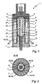
- Electromagnet 1 emerges, which in particular for actuating one shown hydraulic valve for controlling a device for changing the timing of gas exchange valves of an internal combustion engine suitable is.
- This electromagnet 1 is clearly visible as a hollow cylindrical one Coil body 2, which carries a coil winding 3 and on the outer circumference is enclosed by a magnet housing 4 and which end from an upper pole piece 5 on which an electrical connection part 6 rests, and a lower pole piece 7, which is in the hollow cylinder of the coil former 2 protrudes, is limited.
- armature space 9 for an axially movable, cylindrical magnet armature 10 is formed.
- This gastric anchor 10 in turn divides the anchor space 9 a first chamber 11 and a second chamber 12 for pressure equalization of working fluid penetrating into the armature space 9 via the hydraulic valve via a pressure equalization channel described in more detail below Magnetic armature 10 are interconnected.
- the magnet armature 10 is about one through a central axial bore 13 in the lower pole piece 7 guided push rod 14 with a control piston, not shown, of the hydraulic Valve is connected, the control piston in one sealing against the lower pole piece 7 of the electromagnet 1, likewise Not shown valve housing is guided, the interior of a another pressure equalization channel, also described in more detail below in the lower pole piece 7 connected to the first chamber 11 of the armature space 9 is.
- the magnet armature 10 has a central longitudinal bore 17 according to the invention, despite the push rod 14 lying loosely on the end face, which, as indicated in FIGS. 2, 4 and 6, is smaller in diameter than that largest profile width of the push rod 14 and larger than the smallest profile width of the push rod 14 is formed.
- the end face 15 of the push rod 14 only partially covers the opening of the longitudinal bore 13 in the magnet armature 10, so that the longitudinal bore 13 in the magnet armature 10 forms the pressure compensation channel 18 mentioned above via the free cross-sectional areas of its opening, via which the first chamber 11 with the second Chamber 12 in the armature chamber 9 of the electromagnet 1 is connected.
- Both these cross-sectional areas of the longitudinal bore 17 in the magnet armature 10, which are not covered by the end face 15 of the push rod 14, and the cross-sectional areas of the pressure compensation channels in the lower pole shoe 7 described above each have a total flow cross section of at least 0.5 mm 2 , since this is actuated by the electromagnet 1 Hydraulic valve for controlling a hydraulic device for camshaft adjustment is provided and a static operating pressure of up to 10 bar is present within the hydraulic system of this device.
- the non-magnetizable Metal tube 8 in the hollow cylinder of the bobbin 2 as one-sided closed, cup-shaped copper tube is formed, which the coil winding 3 seals against the working fluid of the hydraulic valve and whose inside 22 is also designed as a guide for the magnet armature 10 is.
- the magnet armature 10 is defined at the upper and lower ends processed by centerless grinding and between the bearings 23, 24 minimally reduced diameter.
- the bearings 23, 24 with a low-friction or wear-reducing, not shown PTFE coating designed to reduce the hysteresis of the Magnet armature and to increase the life of the electromagnet 1 contributes.
Landscapes
- Engineering & Computer Science (AREA)
- Physics & Mathematics (AREA)
- Electromagnetism (AREA)
- Power Engineering (AREA)
- General Engineering & Computer Science (AREA)
- Mechanical Engineering (AREA)
- Magnetically Actuated Valves (AREA)
- Electromagnets (AREA)
Abstract
Description
- Figur 1
- einen Längsschnitt durch eine erste Ausführungsform eines erfindungsgemäß ausgebildeten Elektromagneten;
- Figur 2
- einen Querschnitt A-A nach Figur 1 durch die erste Ausführungsform des erfindungsgemäß ausgebildeten Elektromagneten;
- Figur 3
- einen Längsschnitt durch eine zweite Ausführungsform eines erfindungsgemäß ausgebildeten Elektromagneten;
- Figur 4
- einen Querschnitt A-A nach Figur 3 durch die zweite Ausführungsform des erfindungsgemäß ausgebildeten Elektromagneten;
- Figur 5
- einen Längsschnitt durch eine dritte Ausführungsform eines erfindungsgemäß ausgebildeten Elektromagneten;
- Figur 6
- einen Querschnitt A-A nach Figur 5 durch die dritte Ausführungsform des erfindungsgemäß ausgebildeten Elektromagneten.
- 1
- Elektromagnet
- 2
- Spulenkörper
- 3
- Spulenwicklung
- 4
- Magnetgehäuse
- 5
- oberer Polschuh
- 6
- elektrisches Anschlußteil
- 7
- unterer Polschuh
- 8
- Metallrohr
- 9
- Ankerraum
- 10
- Magnetanker
- 11
- erste Kammer
- 12
- zweite Kammer
- 13
- Axialbohrung
- 14
- Stößelstange
- 15
- Stirnseite
- 16
- Druckausgleichskanal
- 17
- Längsbohrung
- 18
- Druckausgleichskanal
- 19
- Dreikantprofil
- 20
- Vierkantprofil
- 21
- Rundprofil
- 22
- Innenseite von 8
- 23
- Lagerstelle
- 24
- Lagerstelle
Claims (7)
- Elektromagnet, insbesondere Proportionalmagnet zur Betätigung eines hydraulischen Ventils, welches innerhalb eines Hydrauliksystems einer Vorrichtung zum Verändern der Steuerzeiten von Gaswechselventilen einer Brennkraftmaschine angeordnet ist, mit folgenden Merkmalen:dadurch gekennzeichnet, dassder Elektromagnet (1) weist einen hohlzylindrischen Spulenkörper (2) auf, der zumindest eine Spulenwicklung (3) trägt und am Außenumfang von einem Magnetgehäuse (4) umschlossen wird,der Spulenkörper (2) wird von einem oberen Polschuh (5), auf dem ein elektrisches Anschlußteil (6) aufliegt, sowie von einem unteren Polschuh (7), der in den Hohlzylinder des Spulenkörpers (2) hineinragt, begrenzt,im Hohlzylinder des Spulenkörpers (2) ist ein nichtmagnetisierbares Metallrohr (8) angeordnet, dessen Hohlraum als Ankerraum (9) für einen axial beweglichen zylindrischer Magnetanker (10) ausgebildet ist,der Magnetanker (10) teilt den Ankerraum (9) in eine erste Kammer (11) und eine zweite Kammer (12), die über zumindest einen axialen Druckausgleichskanal im Magnetanker (10) miteinander verbunden sind,der Magnetanker (10) steht über eine durch eine Axialbohrung (13) im unteren Polschuh (7) hindurch geführte Stößelstange (14) mit einem Steuerkolben im Ventilgehäuse eines hydraulischen Ventils in Verbindung,der Innenraum des am Elektromagneten (1) befestigten Ventilgehäuses ist über einen weiteren Druckausgleichskanal im unteren Polschuh (7) mit der ersten Kammer (11) des Ankerraumes (9) verbunden,die in der Axialbohrung (13) im unteren Polschuh (7) geführte Stößelstange (14) als vom Magnetanker (10) getrennte, lose Profilstange ausgebildet ist, deren Querschnittsform von der der Axialbohrung (13) abweicht und deren Querschnittsfläche kleiner als die der Axialbohrung (13) ist,so dass die freien Querschnittsräume innerhalb der Axialbohrung (13) im unteren Polschuh (7) zugleich als Druckausgleichskanäle (16) zwischen dem Innenraum des Ventilgehäuses des hydraulischen Ventils und der ersten Kammer (11) im Ankerraum (9) des Elektromagneten (1) nutzbar sind.
- Elektromagnet nach Anspruch 1, dadurch gekennzeichnet, dassder stirnseitig an der Stößelstange (14) anliegende Magnetanker (10) eine zentrische Längsbohrung (17) aufweist, deren Durchmesser kleiner als die größte Profilweite der Stößelstange (14) und größer als die kleinste Profilweite der Stößelstange (14) ausgebildet ist,so dass die Stirnseite (15) der Stößelstange (14) die Längsbohrung (17) im Magnetanker (10) nur teilweise überdeckt und diese somit als Druckausgleichskanal (18) zwischen der ersten Kammer (11) und der zweiten Kammer (12) im Ankerraum (9) des Elektromagneten (1) nutzbar ist.
- Elektromagnet nach Anspruch 1, dadurch gekennzeichnet, dassdie Stößelstange (14) bevorzugt als an den Profilkanten abgerundetes Mehrkantprofil (19, 20) oder als ein- oder mehrseitig abgeflachtes Rundprofil (21) aus einer Messinglegierung ausgebildet ist, welches spanlos durch Strangpressen herstellbar und durch Stanzschneiden ablängbar ist.
- Elektromagnet nach Anspruch 1 und 2, dadurch gekennzeichnet, dasssowohl die Querschnittsflächen der Druckausgleichskanäle (16) im unteren Polschuh (7) als auch die von der Stirnseite (15) der Stößelstange (14) nicht überdeckten Querschnittsflächen der Längsbohrung (17) im Magnetanker (10) jeweils einen Gesamtströmungsquerschnitt von mindestens 0,5 mm2 bei einem statischen Betriebsdruck von bis zu 10 bar aufweisen.
- Elektromagnet nach Anspruch 1, dadurch gekennzeichnet, dassdas nichtmagnetisierbare Metallrohr (8) im Hohlzylinder des Spulenkörpers (2) bevorzugt als einseitig geschlossenes, becherförmiges Kupferrohr ausgebildet ist, welches die Spulenwicklung (3) gegen das Arbeitsfluid des hydraulischen Ventils abdichtet und dessen Innenseite (22) zugleich als Führung für den Magnetanker (10) ausgebildet ist.
- Elektromagnet nach Anspruch 5, dadurch gekennzeichnet, dassder Magnetanker (10) und/oder die Innenseite (22) des nichtmagnetisierbaren Metallrohrs (8) zur Verringerung der Hysterese des Magnetankers (10) sowie zur Erhöhung der Lebensdauer des Elektromagneten (1) bevorzugt eine reibungsarme bzw. verschleißmindernde Beschichtung, beispielsweise eine PTFE-Beschichtung, aufweisen.
- Elektromagnet nach Anspruch 5 oder 6, dadurch gekennzeichnet, dassder Magnetanker (10) zur Definition seiner Lagerstellen (23, 24) an der Innenseite (22) des nichtmagnetisierbaren Metallrohres (8) am oberen und am unteren Ende bevorzugt durch Centerlessschleifen bearbeitet ist, wobei der Durchmesser des Magnetankers (10) zwischen den Lagerstellen (23, 24) minimal reduziert ist.
Applications Claiming Priority (2)
| Application Number | Priority Date | Filing Date | Title |
|---|---|---|---|
| DE10153019 | 2001-10-26 | ||
| DE10153019A DE10153019A1 (de) | 2001-10-26 | 2001-10-26 | Elektromagnet, insbesondere Proportionalmagnet zur Betätigung eines hydraulischen Ventils |
Publications (3)
| Publication Number | Publication Date |
|---|---|
| EP1313110A2 true EP1313110A2 (de) | 2003-05-21 |
| EP1313110A3 EP1313110A3 (de) | 2007-08-15 |
| EP1313110B1 EP1313110B1 (de) | 2010-12-15 |
Family
ID=7703891
Family Applications (1)
| Application Number | Title | Priority Date | Filing Date |
|---|---|---|---|
| EP02021921A Expired - Lifetime EP1313110B1 (de) | 2001-10-26 | 2002-09-28 | Elektromagnet, insbesondere Proportionalmagnet zur Betätigung eines hydraulischen Ventils |
Country Status (8)
| Country | Link |
|---|---|
| US (1) | US6799746B2 (de) |
| EP (1) | EP1313110B1 (de) |
| JP (1) | JP2003203811A (de) |
| KR (1) | KR100906597B1 (de) |
| CN (1) | CN1272553C (de) |
| AT (1) | ATE491868T1 (de) |
| DE (2) | DE10153019A1 (de) |
| ES (1) | ES2355330T3 (de) |
Cited By (5)
| Publication number | Priority date | Publication date | Assignee | Title |
|---|---|---|---|---|
| EP1607988A2 (de) | 2004-06-15 | 2005-12-21 | HYDAC Electronic GmbH | Betätigungsvorrichtung, insbesondere zum Betätigen von Ventilen |
| WO2007045375A1 (de) * | 2005-10-18 | 2007-04-26 | Thomas Magnete Gmbh | Elektromagnet |
| EP2116437A3 (de) * | 2008-04-09 | 2010-10-13 | WABCO GmbH | Schaltmagnetventil |
| EP2469544A1 (de) * | 2010-12-20 | 2012-06-27 | SVM Schultz Verwaltungs-GmbH & Co. KG | Elektromagnet mit Tubus |
| WO2014190980A1 (de) * | 2013-05-28 | 2014-12-04 | Schaeffler Technologies Gmbh & Co. Kg | Zentralventil mit einem elektromagneten zur ansteuerung des zentralventils |
Families Citing this family (48)
| Publication number | Priority date | Publication date | Assignee | Title |
|---|---|---|---|---|
| DE10153019A1 (de) * | 2001-10-26 | 2003-05-08 | Ina Schaeffler Kg | Elektromagnet, insbesondere Proportionalmagnet zur Betätigung eines hydraulischen Ventils |
| US7240894B2 (en) * | 2003-05-30 | 2007-07-10 | Borgwarner Inc. | Pulse width modulated solenoid |
| US7325564B2 (en) * | 2004-03-24 | 2008-02-05 | Keihin Corporation | Linear solenoid valve |
| US7487798B2 (en) * | 2004-03-31 | 2009-02-10 | Keihin Corporation | Linear solenoid valve |
| DE102004051332A1 (de) * | 2004-10-21 | 2006-04-27 | Hydac Electronic Gmbh | Betätigungsvorrichtung |
| DE102005003446A1 (de) * | 2005-01-27 | 2006-08-10 | Schaeffler Kg | Elektromagnetisches Hydraulikventil |
| US7819131B2 (en) * | 2005-02-14 | 2010-10-26 | Cameron International Corporation | Springless compressor valve |
| DE102005023047A1 (de) * | 2005-05-13 | 2007-01-18 | Claas Selbstfahrende Erntemaschinen Gmbh | Einzugsorgansteuerung für landwirtschaftliche Arbeitsmaschine |
| CA2511070A1 (en) * | 2005-06-29 | 2006-12-29 | Scireq Scientific Respiratory Equipment Inc. | Self-actuated cylinder and oscillation spirometer |
| CN1928370B (zh) * | 2006-10-10 | 2013-06-19 | 张玉宝 | 一种磁阻式无杆比例电磁阀及其伺服控制方法 |
| DE102006055796A1 (de) * | 2006-11-27 | 2008-05-29 | Robert Bosch Gmbh | Druckregelventil |
| DE102007014559A1 (de) * | 2007-03-27 | 2008-10-02 | Robert Bosch Gmbh | Druckrohr für ein Wegemesssystem |
| DE102008008118B4 (de) | 2008-02-08 | 2026-01-15 | Schaeffler Technologies AG & Co. KG | Elektromagnetische Stelleinheit für ein hydraulisches Wegeventil |
| DE102008008761A1 (de) * | 2008-02-12 | 2009-08-13 | Robert Bosch Gmbh | Betätigungsmagnet |
| DE102008010646A1 (de) | 2008-02-22 | 2009-08-27 | Schaeffler Kg | Elektromagnetische Stelleinheit für ein hydraulisches Wegeventil |
| DE102008010649A1 (de) | 2008-02-22 | 2009-08-27 | Schaeffler Kg | Elektromagnetische Stelleinheit für ein hydraulisches Wegeventil |
| DE102008010648A1 (de) | 2008-02-22 | 2009-08-27 | Schaeffler Kg | Elektromagnetische Stelleinheit für ein hydraulisches Wegeventil |
| US8025489B2 (en) * | 2008-09-04 | 2011-09-27 | William Francis Shacklee | Portable, remote electromagnetic power system |
| DE102008064604B4 (de) * | 2008-11-12 | 2018-09-20 | Svm Schultz Verwaltungs-Gmbh & Co. Kg | Elektromagnetisch betätigbares Fluid-Ventil |
| DE102008059012A1 (de) | 2008-11-26 | 2010-05-27 | Schaeffler Kg | Elektromagnetische Stelleinheit für ein hydraulisches Wegeventil und Verfahren zu dessen Montage |
| DE102009006355A1 (de) | 2009-01-28 | 2010-07-29 | Schaeffler Technologies Gmbh & Co. Kg | Proportionalmagnet für ein hydraulisches Wegeventil und Verfahren zu dessen Herstellung |
| US8613420B2 (en) * | 2009-06-26 | 2013-12-24 | Magna Powertrain Ag & Co. Kg | Solenoid valve |
| CN102166873A (zh) * | 2010-02-26 | 2011-08-31 | 比亚迪股份有限公司 | 一种具有涂层的钕铁硼磁钢及其制备方法 |
| EP2605254B8 (de) * | 2011-12-12 | 2017-10-04 | Tyco Electronics Belgium EC BVBA | Elektromagnetischer Aktuator |
| DE102012000676A1 (de) * | 2012-01-17 | 2013-07-18 | Knf Flodos Ag | Verdrängerpumpe |
| CN102610358B (zh) * | 2012-04-09 | 2015-10-21 | 梁昌勇 | 双气隙结构双推磁力器 |
| JP5682614B2 (ja) * | 2012-12-04 | 2015-03-11 | 株式会社デンソー | バルブタイミング調整装置 |
| CN103050217B (zh) * | 2012-12-14 | 2016-08-03 | 兰溪市中元电器有限公司 | 自动变速器电磁阀用比例电磁铁 |
| JP6064577B2 (ja) * | 2012-12-19 | 2017-01-25 | 株式会社デンソー | スタータ用電磁スイッチ |
| CN103016824B (zh) * | 2012-12-28 | 2014-08-13 | 大连理工大学 | 一种螺线管式单驱多动电磁铁组件 |
| CN103714940B (zh) * | 2014-01-09 | 2016-04-20 | 浙江弘驰科技股份有限公司 | 一种小型化比例电磁铁 |
| US10269480B2 (en) * | 2015-02-02 | 2019-04-23 | Eagle Industry Co., Ltd. | Solenoid |
| CN105240593B (zh) * | 2015-11-19 | 2018-01-09 | 中国海洋大学 | 一种电磁换向阀 |
| CN106286450B (zh) * | 2016-10-10 | 2018-02-16 | 合肥协力液压科技有限公司 | 电磁压力比例阀 |
| DE102017102015A1 (de) | 2017-02-02 | 2018-08-02 | Schaeffler Technologies AG & Co. KG | Verfahren zur Herstellung einer elektromagnetischen Stelleinheit für ein hydraulisches Wegeventil sowie elektromagnetische Stelleinheit |
| US10259563B2 (en) * | 2017-05-19 | 2019-04-16 | Kitty Hawk Corporation | Combined fan and motor |
| DE102018000449A1 (de) * | 2018-01-19 | 2019-07-25 | Hydac Fluidtechnik Gmbh | Betätigungsmagnet |
| DE102018118754A1 (de) * | 2018-08-02 | 2020-02-06 | ECO Holding 1 GmbH | Hydraulikventil und Aktuator für ein Hydraulikventil |
| US10943720B2 (en) * | 2018-08-13 | 2021-03-09 | Honeywell International Inc. | Solenoid including armature anti-rotation structure |
| CN109630739A (zh) * | 2018-12-06 | 2019-04-16 | 河南平高电气股份有限公司 | 一种电磁阀用电磁铁 |
| KR102200067B1 (ko) * | 2019-07-19 | 2021-01-08 | 주식회사 인팩 | 차량용 솔레노이드 장치 |
| JP2021163795A (ja) * | 2020-03-30 | 2021-10-11 | 新電元メカトロニクス株式会社 | ソレノイド |
| DE102020117501B3 (de) | 2020-07-02 | 2021-11-04 | Pierburg Gmbh | Elektromagnet und Verfahren zum Montieren eines Elektromagneten |
| US11783980B2 (en) * | 2021-01-19 | 2023-10-10 | Honeywell International Inc. | Solenoid with no metal-to-metal wear couples in default position |
| US11649060B2 (en) | 2021-09-14 | 2023-05-16 | Beta Air, Llc | Method and system for propulsion in an electric aircraft |
| CN114927723B (zh) * | 2022-05-25 | 2025-12-16 | 北京亿华通科技股份有限公司 | 一种燃料电池用氢空压差调控装置及燃料电池系统 |
| CN115489476B (zh) * | 2022-10-09 | 2025-02-18 | 宁波均胜汽车安全系统有限公司 | 电磁顶升器及整车前部结构 |
| CN115547614A (zh) * | 2022-10-25 | 2022-12-30 | 安阳凯地磁力科技股份有限公司 | 一种双工位电磁铁 |
Citations (3)
| Publication number | Priority date | Publication date | Assignee | Title |
|---|---|---|---|---|
| DE4343879A1 (de) | 1993-12-08 | 1995-06-14 | Rexroth Mannesmann Gmbh | Elektromagnet, insbesondere für ein hydraulisches Ventil |
| DE19504185A1 (de) | 1995-02-09 | 1996-08-14 | Rexroth Mannesmann Gmbh | Elektromagnet mit hülsenförmigem Gehäuse |
| DE19716517A1 (de) | 1997-04-21 | 1998-10-22 | Thomas Magnete Gmbh | Elektromagnet mit einem Anker mit Kunststoffstange |
Family Cites Families (23)
| Publication number | Priority date | Publication date | Assignee | Title |
|---|---|---|---|---|
| DE8317753U1 (de) * | 1984-11-29 | Robert Bosch Gmbh, 7000 Stuttgart | Stelleinrichtung | |
| US2923520A (en) * | 1956-09-24 | 1960-02-02 | Gen Controls Co | Hum-free solenoid mechanism |
| CA1021225A (en) * | 1974-06-28 | 1977-11-22 | General Signal Corporation | Quick-acting valve assembly |
| JPS5840672U (ja) * | 1981-09-14 | 1983-03-17 | 株式会社デンソー | 電磁式リ−ド弁 |
| US4526340A (en) * | 1982-06-28 | 1985-07-02 | Imperial Clevite Inc. | Solenoid valve |
| US4778147A (en) * | 1985-07-27 | 1988-10-18 | Mitsubishi Jidosha Kogyo Kabushiki Kaisha | Electromagnetic solenoid |
| JPH0832477B2 (ja) * | 1987-11-24 | 1996-03-29 | 日立粉末冶金株式会社 | 印字濃淡の少ないインクリボンおよびその製造方法 |
| JPH0636371Y2 (ja) * | 1988-03-14 | 1994-09-21 | シーケーディ株式会社 | 電磁弁 |
| WO1995013945A1 (de) * | 1993-11-18 | 1995-05-26 | Itt Automotive Europe Gmbh | Elektromagnetventil, insbesondere für hydraulische bremsanlagen mit schlupfregelung |
| DE4420176A1 (de) * | 1994-06-09 | 1995-12-14 | Bosch Gmbh Robert | Ventilnadel für ein elektromagnetisch betätigbares Ventil |
| DE19510288A1 (de) * | 1995-03-22 | 1996-09-26 | Teves Gmbh Alfred | Elektromagnetventil mit Druckbegrenzungsfunktion, isnbesondere für hydraulische Kraftfahrzeug-Bremsanlageen mit Schlupfregelung und/oder automatischem Bremseneingriff zur Fahrdynamikregelung |
| US5969589A (en) * | 1996-08-28 | 1999-10-19 | Ferrofluidics Corporation | Quiet ferrofluid solenoid |
| JP3784134B2 (ja) * | 1997-05-14 | 2006-06-07 | 株式会社豊田自動織機 | 制御弁 |
| US5947092A (en) * | 1997-09-03 | 1999-09-07 | Siemens Canada Limited | Space-efficient electromagnetic actuated exhaust gas recirculation valve |
| DE19805049A1 (de) * | 1998-02-09 | 1999-08-12 | Schultz Wolfgang E | Elektromagnet |
| US6182646B1 (en) * | 1999-03-11 | 2001-02-06 | Borgwarner Inc. | Electromechanically actuated solenoid exhaust gas recirculation valve |
| DE19924837B4 (de) * | 1999-05-29 | 2005-05-19 | Hydraulik-Ring Gmbh | Elektromagnet für ein Druckmittel steuerndes Ventil |
| DE19934846A1 (de) * | 1999-07-24 | 2001-01-25 | Hydraulik Ring Gmbh | Elektromagnet und hydraulisches Ventil mit einem Elektromagneten |
| DE10153019A1 (de) * | 2001-10-26 | 2003-05-08 | Ina Schaeffler Kg | Elektromagnet, insbesondere Proportionalmagnet zur Betätigung eines hydraulischen Ventils |
| JP2003322274A (ja) * | 2002-04-26 | 2003-11-14 | Tgk Co Ltd | 電磁制御弁 |
| DE10252431A1 (de) * | 2002-11-12 | 2004-05-27 | Ina-Schaeffler Kg | Elektromagnetisches Hydraulikventil, insbesondere 3/2-Wegeschaltventil zur Steuerung eines variablen Ventiltriebes einer Brennkraftmaschine |
| DE10359363A1 (de) * | 2003-12-18 | 2005-07-14 | Ina-Schaeffler Kg | Elektromagnetisches Hydraulikventil, inbesondere 3/2-Wegeschaltventil zur Steuerung eines variablen Ventiltriebes einer Brennkraftmaschine |
| DE10359364B4 (de) * | 2003-12-18 | 2012-10-11 | Schaeffler Technologies Gmbh & Co. Kg | Elektromagnetisches Hydraulikventil, insbesondere 3/2-Wegeschaltventil zur Steuerung eines varialblen Ventiltriebes einer Brennkraftmaschine |
-
2001
- 2001-10-26 DE DE10153019A patent/DE10153019A1/de not_active Withdrawn
-
2002
- 2002-09-28 AT AT02021921T patent/ATE491868T1/de active
- 2002-09-28 ES ES02021921T patent/ES2355330T3/es not_active Expired - Lifetime
- 2002-09-28 DE DE50214812T patent/DE50214812D1/de not_active Expired - Lifetime
- 2002-09-28 EP EP02021921A patent/EP1313110B1/de not_active Expired - Lifetime
- 2002-10-23 KR KR1020020064801A patent/KR100906597B1/ko not_active Expired - Fee Related
- 2002-10-24 JP JP2002309666A patent/JP2003203811A/ja active Pending
- 2002-10-25 CN CNB021471835A patent/CN1272553C/zh not_active Expired - Fee Related
- 2002-10-28 US US10/282,313 patent/US6799746B2/en not_active Expired - Lifetime
Patent Citations (3)
| Publication number | Priority date | Publication date | Assignee | Title |
|---|---|---|---|---|
| DE4343879A1 (de) | 1993-12-08 | 1995-06-14 | Rexroth Mannesmann Gmbh | Elektromagnet, insbesondere für ein hydraulisches Ventil |
| DE19504185A1 (de) | 1995-02-09 | 1996-08-14 | Rexroth Mannesmann Gmbh | Elektromagnet mit hülsenförmigem Gehäuse |
| DE19716517A1 (de) | 1997-04-21 | 1998-10-22 | Thomas Magnete Gmbh | Elektromagnet mit einem Anker mit Kunststoffstange |
Cited By (8)
| Publication number | Priority date | Publication date | Assignee | Title |
|---|---|---|---|---|
| EP1607988A2 (de) | 2004-06-15 | 2005-12-21 | HYDAC Electronic GmbH | Betätigungsvorrichtung, insbesondere zum Betätigen von Ventilen |
| EP1607988A3 (de) * | 2004-06-15 | 2008-02-20 | HYDAC Electronic GmbH | Betätigungsvorrichtung, insbesondere zum Betätigen von Ventilen |
| WO2007045375A1 (de) * | 2005-10-18 | 2007-04-26 | Thomas Magnete Gmbh | Elektromagnet |
| EP2116437A3 (de) * | 2008-04-09 | 2010-10-13 | WABCO GmbH | Schaltmagnetventil |
| EP2469544A1 (de) * | 2010-12-20 | 2012-06-27 | SVM Schultz Verwaltungs-GmbH & Co. KG | Elektromagnet mit Tubus |
| US8754732B2 (en) | 2010-12-20 | 2014-06-17 | Svm Schultz Verwaltungs-Gmbh & Co. Kg | Solenoid with a tube |
| RU2580946C2 (ru) * | 2010-12-20 | 2016-04-10 | СФМ Шульц Фервальтунгс-Гмбх унд Ко.КГ | Электромагнит с тубусом |
| WO2014190980A1 (de) * | 2013-05-28 | 2014-12-04 | Schaeffler Technologies Gmbh & Co. Kg | Zentralventil mit einem elektromagneten zur ansteuerung des zentralventils |
Also Published As
| Publication number | Publication date |
|---|---|
| ATE491868T1 (de) | 2011-01-15 |
| EP1313110A3 (de) | 2007-08-15 |
| EP1313110B1 (de) | 2010-12-15 |
| ES2355330T3 (es) | 2011-03-24 |
| DE50214812D1 (de) | 2011-01-27 |
| DE10153019A1 (de) | 2003-05-08 |
| KR100906597B1 (ko) | 2009-07-09 |
| JP2003203811A (ja) | 2003-07-18 |
| CN1272553C (zh) | 2006-08-30 |
| US20030080305A1 (en) | 2003-05-01 |
| CN1414251A (zh) | 2003-04-30 |
| US6799746B2 (en) | 2004-10-05 |
| KR20030035932A (ko) | 2003-05-09 |
Similar Documents
| Publication | Publication Date | Title |
|---|---|---|
| EP1313110B1 (de) | Elektromagnet, insbesondere Proportionalmagnet zur Betätigung eines hydraulischen Ventils | |
| DE69715712T2 (de) | Hydraulisches Elektromagnetventil | |
| EP2740980B1 (de) | Stetig verstellbares hydraulisches Einbauventil | |
| EP2246601B1 (de) | Elektromagnetisches Hydraulikventil | |
| WO2004044467A1 (de) | Elektromagnetisches hydraulikventil, insbesondere 3/2-wegeschaltventil zur steuerung eines variablen ventiltriebes einer brennkraftmaschine | |
| DE102008059012A1 (de) | Elektromagnetische Stelleinheit für ein hydraulisches Wegeventil und Verfahren zu dessen Montage | |
| EP2213921B1 (de) | Druckregelventil | |
| EP2116437A2 (de) | Schaltmagnetventil | |
| DE4311269B4 (de) | Anordnung zur Verwendung in einem Elektromagneten | |
| DE68916435T2 (de) | Schnell ansprechendes, druckausgeglichenes, elektromagnetisches hochdruck-steuerventil. | |
| DE102019218094A1 (de) | Elektromagnetische Betätigungseinrichtung | |
| DE112021005169T5 (de) | Zylinderspule, Dämpfungskrafteinstellungsmechanismus und Stoßdämpfer mit einstellbarer Dämpfungskraft | |
| DE102013209926A1 (de) | Verstellbare Dämpfventileinrichtung | |
| DE102015107039B4 (de) | Elektromagnetventil sowie sicherheitsrelevantes Pneumatiksystem | |
| DE102014108700A1 (de) | Zentralaktuator für einen Schwenkmotorversteller einer Nockenwelle | |
| DE4037824A1 (de) | Hydraulische stelleinrichtung | |
| DE112022001216T5 (de) | Solenoid, Dämpfungskrafteinstellungsmechanismus und Stossdämpfer mit einstellbarer Dämpfungskraft | |
| EP2299458B1 (de) | Elektromagnet | |
| DE112021005245T5 (de) | Magnetspule, Dämpfungskrafteinstellmechanismus und dämpfungskrafteinstellbarer Stoßdämpfer | |
| DE102005041395B4 (de) | Hydraulisches Wegeventil | |
| WO2010066536A1 (de) | Betätigungselement einer elektromagnetischen stelleinheit eines hydraulikventils | |
| EP1317638B1 (de) | Wegeventil | |
| DE112023000985T5 (de) | Solenoid, mechanismus zur einstellung einer dämpfungskraft und stossdämpfer mit einstellbarer dämpfungskraft | |
| DE102018000058B4 (de) | Betätigungsvorrichtung, insbesondere zum Betätigen von Ventilen,sowie Ventilansteuersystem | |
| DE19859116B4 (de) | Elektromagnet |
Legal Events
| Date | Code | Title | Description |
|---|---|---|---|
| PUAI | Public reference made under article 153(3) epc to a published international application that has entered the european phase |
Free format text: ORIGINAL CODE: 0009012 |
|
| 17P | Request for examination filed |
Effective date: 20020928 |
|
| AK | Designated contracting states |
Designated state(s): AT BE BG CH CY CZ DE DK EE ES FI FR GB GR IE IT LI LU MC NL PT SE SK TR |
|
| AX | Request for extension of the european patent |
Extension state: AL LT LV MK RO SI |
|
| RAP1 | Party data changed (applicant data changed or rights of an application transferred) |
Owner name: SCHAEFFLER KG |
|
| PUAL | Search report despatched |
Free format text: ORIGINAL CODE: 0009013 |
|
| AK | Designated contracting states |
Kind code of ref document: A3 Designated state(s): AT BE BG CH CY CZ DE DK EE ES FI FR GB GR IE IT LI LU MC NL PT SE SK TR |
|
| AX | Request for extension of the european patent |
Extension state: AL LT LV MK RO SI |
|
| 17Q | First examination report despatched |
Effective date: 20071127 |
|
| AKX | Designation fees paid |
Designated state(s): AT BE BG CH CY CZ DE DK EE ES FI FR GB GR IE IT LI LU MC NL PT SE SK TR |
|
| GRAP | Despatch of communication of intention to grant a patent |
Free format text: ORIGINAL CODE: EPIDOSNIGR1 |
|
| RIC1 | Information provided on ipc code assigned before grant |
Ipc: F01L 1/344 20060101AFI20100108BHEP |
|
| GRAJ | Information related to disapproval of communication of intention to grant by the applicant or resumption of examination proceedings by the epo deleted |
Free format text: ORIGINAL CODE: EPIDOSDIGR1 |
|
| GRAP | Despatch of communication of intention to grant a patent |
Free format text: ORIGINAL CODE: EPIDOSNIGR1 |
|
| GRAS | Grant fee paid |
Free format text: ORIGINAL CODE: EPIDOSNIGR3 |
|
| GRAA | (expected) grant |
Free format text: ORIGINAL CODE: 0009210 |
|
| RAP1 | Party data changed (applicant data changed or rights of an application transferred) |
Owner name: SCHAEFFLER TECHNOLOGIES GMBH & CO. KG |
|
| AK | Designated contracting states |
Kind code of ref document: B1 Designated state(s): AT BE BG CH CY CZ DE DK EE ES FI FR GB GR IE IT LI LU MC NL PT SE SK TR |
|
| REG | Reference to a national code |
Ref country code: GB Ref legal event code: FG4D Free format text: NOT ENGLISH Ref country code: CH Ref legal event code: EP |
|
| REG | Reference to a national code |
Ref country code: IE Ref legal event code: FG4D |
|
| REF | Corresponds to: |
Ref document number: 50214812 Country of ref document: DE Date of ref document: 20110127 Kind code of ref document: P |
|
| REG | Reference to a national code |
Ref country code: ES Ref legal event code: FG2A Ref document number: 2355330 Country of ref document: ES Kind code of ref document: T3 Effective date: 20110324 |
|
| REG | Reference to a national code |
Ref country code: NL Ref legal event code: VDEP Effective date: 20101215 |
|
| PG25 | Lapsed in a contracting state [announced via postgrant information from national office to epo] |
Ref country code: NL Free format text: LAPSE BECAUSE OF FAILURE TO SUBMIT A TRANSLATION OF THE DESCRIPTION OR TO PAY THE FEE WITHIN THE PRESCRIBED TIME-LIMIT Effective date: 20101215 Ref country code: FI Free format text: LAPSE BECAUSE OF FAILURE TO SUBMIT A TRANSLATION OF THE DESCRIPTION OR TO PAY THE FEE WITHIN THE PRESCRIBED TIME-LIMIT Effective date: 20101215 Ref country code: BG Free format text: LAPSE BECAUSE OF FAILURE TO SUBMIT A TRANSLATION OF THE DESCRIPTION OR TO PAY THE FEE WITHIN THE PRESCRIBED TIME-LIMIT Effective date: 20110315 Ref country code: CY Free format text: LAPSE BECAUSE OF FAILURE TO SUBMIT A TRANSLATION OF THE DESCRIPTION OR TO PAY THE FEE WITHIN THE PRESCRIBED TIME-LIMIT Effective date: 20101215 Ref country code: SE Free format text: LAPSE BECAUSE OF FAILURE TO SUBMIT A TRANSLATION OF THE DESCRIPTION OR TO PAY THE FEE WITHIN THE PRESCRIBED TIME-LIMIT Effective date: 20101215 |
|
| REG | Reference to a national code |
Ref country code: IE Ref legal event code: FD4D |
|
| PG25 | Lapsed in a contracting state [announced via postgrant information from national office to epo] |
Ref country code: PT Free format text: LAPSE BECAUSE OF FAILURE TO SUBMIT A TRANSLATION OF THE DESCRIPTION OR TO PAY THE FEE WITHIN THE PRESCRIBED TIME-LIMIT Effective date: 20110415 Ref country code: IE Free format text: LAPSE BECAUSE OF FAILURE TO SUBMIT A TRANSLATION OF THE DESCRIPTION OR TO PAY THE FEE WITHIN THE PRESCRIBED TIME-LIMIT Effective date: 20101215 Ref country code: EE Free format text: LAPSE BECAUSE OF FAILURE TO SUBMIT A TRANSLATION OF THE DESCRIPTION OR TO PAY THE FEE WITHIN THE PRESCRIBED TIME-LIMIT Effective date: 20101215 Ref country code: CZ Free format text: LAPSE BECAUSE OF FAILURE TO SUBMIT A TRANSLATION OF THE DESCRIPTION OR TO PAY THE FEE WITHIN THE PRESCRIBED TIME-LIMIT Effective date: 20101215 Ref country code: GR Free format text: LAPSE BECAUSE OF FAILURE TO SUBMIT A TRANSLATION OF THE DESCRIPTION OR TO PAY THE FEE WITHIN THE PRESCRIBED TIME-LIMIT Effective date: 20110316 |
|
| PG25 | Lapsed in a contracting state [announced via postgrant information from national office to epo] |
Ref country code: SK Free format text: LAPSE BECAUSE OF FAILURE TO SUBMIT A TRANSLATION OF THE DESCRIPTION OR TO PAY THE FEE WITHIN THE PRESCRIBED TIME-LIMIT Effective date: 20101215 |
|
| PLBE | No opposition filed within time limit |
Free format text: ORIGINAL CODE: 0009261 |
|
| STAA | Information on the status of an ep patent application or granted ep patent |
Free format text: STATUS: NO OPPOSITION FILED WITHIN TIME LIMIT |
|
| PG25 | Lapsed in a contracting state [announced via postgrant information from national office to epo] |
Ref country code: DK Free format text: LAPSE BECAUSE OF FAILURE TO SUBMIT A TRANSLATION OF THE DESCRIPTION OR TO PAY THE FEE WITHIN THE PRESCRIBED TIME-LIMIT Effective date: 20101215 |
|
| 26N | No opposition filed |
Effective date: 20110916 |
|
| PGFP | Annual fee paid to national office [announced via postgrant information from national office to epo] |
Ref country code: GB Payment date: 20110930 Year of fee payment: 10 |
|
| REG | Reference to a national code |
Ref country code: DE Ref legal event code: R097 Ref document number: 50214812 Country of ref document: DE Effective date: 20110916 |
|
| PGFP | Annual fee paid to national office [announced via postgrant information from national office to epo] |
Ref country code: FR Payment date: 20111012 Year of fee payment: 10 |
|
| REG | Reference to a national code |
Ref country code: CH Ref legal event code: PFA Owner name: SCHAEFFLER TECHNOLOGIES AG & CO. KG Free format text: SCHAEFFLER TECHNOLOGIES GMBH & CO. KG#INDUSTRIESTRASSE 1-3#91074 HERZOGENAURACH (DE) -TRANSFER TO- SCHAEFFLER TECHNOLOGIES AG & CO. KG#INDUSTRIESTRASSE 1-3#91074 HERZOGENAURACH (DE) |
|
| BERE | Be: lapsed |
Owner name: SCHAEFFLER TECHNOLOGIES G.M.B.H. & CO. KG Effective date: 20110930 |
|
| PG25 | Lapsed in a contracting state [announced via postgrant information from national office to epo] |
Ref country code: MC Free format text: LAPSE BECAUSE OF NON-PAYMENT OF DUE FEES Effective date: 20110930 |
|
| REG | Reference to a national code |
Ref country code: CH Ref legal event code: PL |
|
| PG25 | Lapsed in a contracting state [announced via postgrant information from national office to epo] |
Ref country code: BE Free format text: LAPSE BECAUSE OF NON-PAYMENT OF DUE FEES Effective date: 20110930 |
|
| PG25 | Lapsed in a contracting state [announced via postgrant information from national office to epo] |
Ref country code: LI Free format text: LAPSE BECAUSE OF NON-PAYMENT OF DUE FEES Effective date: 20110930 Ref country code: CH Free format text: LAPSE BECAUSE OF NON-PAYMENT OF DUE FEES Effective date: 20110930 |
|
| REG | Reference to a national code |
Ref country code: DE Ref legal event code: R081 Ref document number: 50214812 Country of ref document: DE Owner name: SCHAEFFLER TECHNOLOGIES AG & CO. KG, DE Free format text: FORMER OWNER: SCHAEFFLER TECHNOLOGIES GMBH & CO. KG, 91074 HERZOGENAURACH, DE Effective date: 20120828 Ref country code: DE Ref legal event code: R081 Ref document number: 50214812 Country of ref document: DE Owner name: SCHAEFFLER TECHNOLOGIES GMBH & CO. KG, DE Free format text: FORMER OWNER: SCHAEFFLER TECHNOLOGIES GMBH & CO. KG, 91074 HERZOGENAURACH, DE Effective date: 20120828 |
|
| REG | Reference to a national code |
Ref country code: AT Ref legal event code: MM01 Ref document number: 491868 Country of ref document: AT Kind code of ref document: T Effective date: 20110928 |
|
| PG25 | Lapsed in a contracting state [announced via postgrant information from national office to epo] |
Ref country code: AT Free format text: LAPSE BECAUSE OF NON-PAYMENT OF DUE FEES Effective date: 20110928 |
|
| GBPC | Gb: european patent ceased through non-payment of renewal fee |
Effective date: 20120928 |
|
| PG25 | Lapsed in a contracting state [announced via postgrant information from national office to epo] |
Ref country code: LU Free format text: LAPSE BECAUSE OF NON-PAYMENT OF DUE FEES Effective date: 20110928 |
|
| REG | Reference to a national code |
Ref country code: FR Ref legal event code: ST Effective date: 20130531 |
|
| PG25 | Lapsed in a contracting state [announced via postgrant information from national office to epo] |
Ref country code: GB Free format text: LAPSE BECAUSE OF NON-PAYMENT OF DUE FEES Effective date: 20120928 |
|
| PG25 | Lapsed in a contracting state [announced via postgrant information from national office to epo] |
Ref country code: FR Free format text: LAPSE BECAUSE OF NON-PAYMENT OF DUE FEES Effective date: 20121001 Ref country code: IT Free format text: LAPSE BECAUSE OF NON-PAYMENT OF DUE FEES Effective date: 20120928 |
|
| PG25 | Lapsed in a contracting state [announced via postgrant information from national office to epo] |
Ref country code: TR Free format text: LAPSE BECAUSE OF FAILURE TO SUBMIT A TRANSLATION OF THE DESCRIPTION OR TO PAY THE FEE WITHIN THE PRESCRIBED TIME-LIMIT Effective date: 20101215 |
|
| REG | Reference to a national code |
Ref country code: DE Ref legal event code: R081 Ref document number: 50214812 Country of ref document: DE Owner name: SCHAEFFLER TECHNOLOGIES GMBH & CO. KG, DE Free format text: FORMER OWNER: SCHAEFFLER TECHNOLOGIES AG & CO. KG, 91074 HERZOGENAURACH, DE Effective date: 20140218 Ref country code: DE Ref legal event code: R081 Ref document number: 50214812 Country of ref document: DE Owner name: SCHAEFFLER TECHNOLOGIES AG & CO. KG, DE Free format text: FORMER OWNER: SCHAEFFLER TECHNOLOGIES AG & CO. KG, 91074 HERZOGENAURACH, DE Effective date: 20140218 |
|
| REG | Reference to a national code |
Ref country code: DE Ref legal event code: R081 Ref document number: 50214812 Country of ref document: DE Owner name: SCHAEFFLER TECHNOLOGIES AG & CO. KG, DE Free format text: FORMER OWNER: SCHAEFFLER TECHNOLOGIES GMBH & CO. KG, 91074 HERZOGENAURACH, DE Effective date: 20150211 |
|
| REG | Reference to a national code |
Ref country code: ES Ref legal event code: PC2A Owner name: SCHAEFFLER TECHNOLOGIES AG & CO.KG Effective date: 20150512 |
|
| PGFP | Annual fee paid to national office [announced via postgrant information from national office to epo] |
Ref country code: ES Payment date: 20181024 Year of fee payment: 17 |
|
| REG | Reference to a national code |
Ref country code: ES Ref legal event code: FD2A Effective date: 20210129 |
|
| PG25 | Lapsed in a contracting state [announced via postgrant information from national office to epo] |
Ref country code: ES Free format text: LAPSE BECAUSE OF NON-PAYMENT OF DUE FEES Effective date: 20190929 |
|
| PGFP | Annual fee paid to national office [announced via postgrant information from national office to epo] |
Ref country code: DE Payment date: 20211118 Year of fee payment: 20 |
|
| REG | Reference to a national code |
Ref country code: DE Ref legal event code: R071 Ref document number: 50214812 Country of ref document: DE |
|
| P01 | Opt-out of the competence of the unified patent court (upc) registered |
Effective date: 20230522 |