EP1312872A2 - Mechanismus zur lösbaren Montage eines Luftstromverteilers an das eines Belüftungskanals - Google Patents
Mechanismus zur lösbaren Montage eines Luftstromverteilers an das eines Belüftungskanals Download PDFInfo
- Publication number
- EP1312872A2 EP1312872A2 EP02079416A EP02079416A EP1312872A2 EP 1312872 A2 EP1312872 A2 EP 1312872A2 EP 02079416 A EP02079416 A EP 02079416A EP 02079416 A EP02079416 A EP 02079416A EP 1312872 A2 EP1312872 A2 EP 1312872A2
- Authority
- EP
- European Patent Office
- Prior art keywords
- diffuser
- body part
- control disc
- shaft
- air duct
- Prior art date
- Legal status (The legal status is an assumption and is not a legal conclusion. Google has not performed a legal analysis and makes no representation as to the accuracy of the status listed.)
- Granted
Links
Images

Classifications
-
- F—MECHANICAL ENGINEERING; LIGHTING; HEATING; WEAPONS; BLASTING
- F24—HEATING; RANGES; VENTILATING
- F24F—AIR-CONDITIONING; AIR-HUMIDIFICATION; VENTILATION; USE OF AIR CURRENTS FOR SCREENING
- F24F13/00—Details common to, or for air-conditioning, air-humidification, ventilation or use of air currents for screening
- F24F13/08—Air-flow control members, e.g. louvres, grilles, flaps or guide plates
- F24F13/082—Grilles, registers or guards
- F24F13/084—Grilles, registers or guards with mounting arrangements, e.g. snap fasteners for mounting to the wall or duct
-
- F—MECHANICAL ENGINEERING; LIGHTING; HEATING; WEAPONS; BLASTING
- F24—HEATING; RANGES; VENTILATING
- F24F—AIR-CONDITIONING; AIR-HUMIDIFICATION; VENTILATION; USE OF AIR CURRENTS FOR SCREENING
- F24F13/00—Details common to, or for air-conditioning, air-humidification, ventilation or use of air currents for screening
- F24F13/02—Ducting arrangements
- F24F13/06—Outlets for directing or distributing air into rooms or spaces, e.g. ceiling air diffuser
Definitions
- the present invention relates to a mechanism for mounting an air diffuser to the interior wall of an air duct, the diffuser comprising a body part with a shaft adjustable relative to the diffuser body part in the air flow direction and having a control disc affixed to the distal end of the shaft, whereby the spacing between the diffuser body part and the diffuser control disc forms an adjustable air flow gap.
- the air diffuser according to the invention is characterized in that the shaft of the diffuser control disc at the end portion of the diffuser inserted in the air duct is connected to the diffuser body part by means of a flexible springed element having a shape flexibly yielding in the direction of the control disc shaft such that the springed element extends partially outside said diffuser body part in at least two substantially opposite points relative to the control disc shaft, whereby an imaginary circle drawn about the distal ends of the springed element has a larger diameter than the outer diameter of the diffuser body part at the perimeter of the diffuser portion to be inserted in the air duct and that the diameter of the imaginary circle can be reduced by pressing the diffuser control disc in the direction of the control disc shaft inward relative to the diffuser body part toward the interior of the air duct.
- a preferred embodiment of the invention is characterized in that the springed element is made from a wire material and its distal ends are adapted to extend through the wall of the diffuser body part to the exterior side thereof and that the springed element is connected to an adjuster nut provided with an inner thread by means of which it rotates about the control disc shaft.
- Another preferred embodiment of the invention is characterized in that the distal ends of the springed element are bent from the general plane of the spring-wire element in the direction of the diffuser control disc.
- a still another preferred embodiment of the invention is characterized in that the distal ends of the springed element are bent about 40-80°, advantageously about 50-70°, toward the diffuser control disc.
- the benefits of the invention are appreciated in its extremely simple and secure-to-use mounting mechanism. Mounting and dismounting of the air diffuser takes place easily and cleanly without causing any damage to the diffuser or the air duct. Furthermore, no extra accessories or tools are needed to mount and dismount the diffuser.
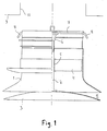
- FIG. 1 therein is shown an air diffuser according to the invention suitable for use as an inlet air diffuser or outlet air diffuser.
- reference numeral 1 generally denotes the body part of the diffuser having a control disc 3 mounted thereon by means of a shaft 2 that extends through the entire longitudinal length of the diffuser.
- the control disc 3 is affixed to the shaft 2.
- To the interior of the diffuser body part 1 is adapted a bridge member 4 extending diagonally over the entire interior diameter of the diffuser body part and having at the center thereof a guide bushing for supporting the diffuser control disc shaft 2.
- the shaft 2 is adapted freely movable in its longitudinal direction relative to the bridge member 4.
- an adjuster nut 6 with a compatible inner thread is adapted to rotate on the control disc shaft.
- the spacing of the air flow gap 11 remaining between the control disc 3 and the diffuser body part 1 can be adjusted by rotating the control disc, whereby the shaft rotates relative to the adjuster nut.
- a springed element 7 which is made from a wire-like material and whose distal ends are adapted to extend through and outside the wall of the diffuser body part 1.
- the distal ends of the springed wire element 7 are denoted by reference numerals 8.
- the distance between the distal ends of the element (or in other words, the diameter of an imaginary circle drawn about the distal ends of the element) in the rest position (FIG. 1) of the springed element is made greater than the outer diameter of that portion of the diffuser body part 1 which is intended to be inserted in an air duct 10 terminated on a wall 9 or room ceiling.
- the distal ends 8 of the springed element 7 are bent “downward", that is, toward the control disc.
- the element tips are bent to angle of, e.g., about 40-80°, advantageously about 50-70°.
- FIG. 2 is shown the initial state of diffuser installation having the control disc 3 pushed inward relative to the diffuser body part 1.
- the air flow gap 11 Prior to mounting the diffuser, the air flow gap 11 must obviously be adjusted sufficiently wide.
- the springed element 7 is forced to bow in the fashion shown in FIG. 2, whereby the distance between the distal ends 8 of the springed element 7 is reduced and the distal ends 8 of the element are aligned parallel to the walls of the air duct.
- the control disc in this inward-pushed position, it is easy to insert the diffuser body into the air duct 10 as far as to make the diffuser body collar 12 to fit flush with the surface of the wall 9.
- the hold of the control disc 3 is released, whereby the spring force of the springed element 7 pushes the distal ends 8 thereof against the walls of the air duct 10.
- the air diffuser remains firmly clamped in its place.
- dismounting the air diffuser from the air duct only needs an inward push on the control disc 3 relative to the diffuser body part and then a pulling grip to remove the diffuser.
- Inward pushing of the control disc in regard to the air diffuser body part can be accomplished by using a grip of both hands placed on the rear side of the diffuser body part. Then, the thumbs of both hands are applied on the control disc to push the same inward.
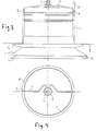
- FIG. 4 is shown an air diffuser mounted in an air duct 10 in a view elucidating a practicable fashion of implementing the springed wire element 7.
- the distal ends 8 of the springed element 7 are tensioned against the inner wall of the air duct 10 so as to keep the diffuser firmly in place.
- the connection of the springed element 7 to the adjuster nut 6 can be seen in FIG. 4.
- the springed element 7 may be implemented in plural alternative ways. Nevertheless, it is an essential specification of the invention that the inward pressing of the diffuser control disc relative to the diffuser body part causes a reduction in the distance between the clamping element ends (in other words, in the diameter of an imaginary circle drawn about the clamping element ends) for inserting the air diffuser into an air duct or for withdrawing the diffuser from the duct and that this kind of an air diffuser inserted in an air duct is kept in place in the duct by means of the distal ends or the like clamping portions of the clamping element.
- the number of the springed elements may be plural and the shape of the elements may be varied. Obviously, also the number and shape of the clamping tips may vary.
- an air diffuser according to the invention may include plural other components such as seals, etc.
- other type of springed element may be used such as a leaf spring, for instance.
Landscapes
- Engineering & Computer Science (AREA)
- Chemical & Material Sciences (AREA)
- Combustion & Propulsion (AREA)
- Mechanical Engineering (AREA)
- General Engineering & Computer Science (AREA)
- Duct Arrangements (AREA)
- Aeration Devices For Treatment Of Activated Polluted Sludge (AREA)
- Compressor (AREA)
- Air-Flow Control Members (AREA)
- Jet Pumps And Other Pumps (AREA)
- Lift Valve (AREA)
- Elimination Of Static Electricity (AREA)
- Self-Closing Valves And Venting Or Aerating Valves (AREA)
- Cooling Or The Like Of Electrical Apparatus (AREA)
- Moulds For Moulding Plastics Or The Like (AREA)
Applications Claiming Priority (2)
| Application Number | Priority Date | Filing Date | Title |
|---|---|---|---|
| FI20012211 | 2001-11-14 | ||
| FI20012211A FI119202B (fi) | 2001-11-14 | 2001-11-14 | Mekanismi ilmanvaihtoventtiilin kiinnittämiseksi irrotettavasti ilmanvaihtokanavaan |
Publications (3)
| Publication Number | Publication Date |
|---|---|
| EP1312872A2 true EP1312872A2 (de) | 2003-05-21 |
| EP1312872A3 EP1312872A3 (de) | 2006-11-22 |
| EP1312872B1 EP1312872B1 (de) | 2008-03-05 |
Family
ID=8562254
Family Applications (1)
| Application Number | Title | Priority Date | Filing Date |
|---|---|---|---|
| EP02079416A Expired - Lifetime EP1312872B1 (de) | 2001-11-14 | 2002-10-23 | Mechanismus zur lösbaren Montage eines Luftstromverteilers an einem Belüftungskanal |
Country Status (6)
| Country | Link |
|---|---|
| EP (1) | EP1312872B1 (de) |
| AT (1) | ATE388378T1 (de) |
| DE (1) | DE60225403D1 (de) |
| DK (1) | DK1312872T3 (de) |
| FI (1) | FI119202B (de) |
| NO (1) | NO326502B1 (de) |
Citations (2)
| Publication number | Priority date | Publication date | Assignee | Title |
|---|---|---|---|---|
| FI59299B (fi) | 1978-03-31 | 1981-03-31 | Oston Ltd | Infaestning av ventilationsventil i aendan av en till tvaersnittet rund kanal |
| FI104582B (fi) | 1999-06-11 | 2000-02-29 | Flaekt Oy | Apuväline ilmanvaihtoventtiilin kiinnittämiseksi ilmastointikanavan päähän |
Family Cites Families (3)
| Publication number | Priority date | Publication date | Assignee | Title |
|---|---|---|---|---|
| JPS5818050A (ja) * | 1981-07-24 | 1983-02-02 | Hitachi Ltd | グリル取付装置 |
| IT1309665B1 (it) * | 1999-03-17 | 2002-01-30 | Europlast Spa | Griglia di areazione per condotti di presa d'aria, realizzata in forma composita e col corpo alettato smontabile per la periodica pulizia |
| JP3734991B2 (ja) * | 1999-10-26 | 2006-01-11 | 松下エコシステムズ株式会社 | 換気装置の取付装置 |
-
2001
- 2001-11-14 FI FI20012211A patent/FI119202B/fi not_active IP Right Cessation
-
2002
- 2002-10-23 EP EP02079416A patent/EP1312872B1/de not_active Expired - Lifetime
- 2002-10-23 AT AT02079416T patent/ATE388378T1/de not_active IP Right Cessation
- 2002-10-23 DE DE60225403T patent/DE60225403D1/de not_active Expired - Lifetime
- 2002-10-23 DK DK02079416T patent/DK1312872T3/da active
- 2002-11-08 NO NO20025353A patent/NO326502B1/no not_active IP Right Cessation
Patent Citations (2)
| Publication number | Priority date | Publication date | Assignee | Title |
|---|---|---|---|---|
| FI59299B (fi) | 1978-03-31 | 1981-03-31 | Oston Ltd | Infaestning av ventilationsventil i aendan av en till tvaersnittet rund kanal |
| FI104582B (fi) | 1999-06-11 | 2000-02-29 | Flaekt Oy | Apuväline ilmanvaihtoventtiilin kiinnittämiseksi ilmastointikanavan päähän |
Also Published As
| Publication number | Publication date |
|---|---|
| NO20025353L (no) | 2003-05-15 |
| NO326502B1 (no) | 2008-12-15 |
| FI119202B (fi) | 2008-08-29 |
| DK1312872T3 (da) | 2008-06-23 |
| ATE388378T1 (de) | 2008-03-15 |
| FI20012211L (fi) | 2003-06-27 |
| NO20025353D0 (no) | 2002-11-08 |
| DE60225403D1 (de) | 2008-04-17 |
| EP1312872A3 (de) | 2006-11-22 |
| EP1312872B1 (de) | 2008-03-05 |
| FI20012211A0 (fi) | 2001-11-14 |
Similar Documents
| Publication | Publication Date | Title |
|---|---|---|
| JP2009138939A (ja) | マルチチューブクリップ | |
| CN100383405C (zh) | 具有包括风扇叶轮快速固定部件的内转子电机的风扇 | |
| JP3278840B2 (ja) | 内視鏡の湾曲操作装置 | |
| EP1312872B1 (de) | Mechanismus zur lösbaren Montage eines Luftstromverteilers an einem Belüftungskanal | |
| US20050139417A1 (en) | Decorative tail pipe mounted apparatus for an automobile | |
| US20090274330A1 (en) | Microphone Mount for a Cabinet | |
| EP1185828B1 (de) | Zubehör zur montage eines luftstromverteilers an das ende eines belüftungskanals | |
| JP4685848B2 (ja) | 取り外し装置および方法 | |
| US8272113B1 (en) | Grommet installation device and method | |
| CN100438733C (zh) | 用于将壳体紧固到壁开口中的机构 | |
| US7730835B2 (en) | Holding apparatus for holding a flexible plate on a circumferential surface of a holder of a printing machine | |
| SE525623C2 (sv) | Skruvnyckel med fixeringsanordning till mutter | |
| JP5941412B2 (ja) | 外部ミラーユニット、ミラー支持部、および外部ミラーユニットの組立方法 | |
| JP3805071B2 (ja) | 火災感知器の着脱器 | |
| JP3170436B2 (ja) | 内視鏡用バルブ装置 | |
| JP2004058258A (ja) | 自動ドライバーの付属品 | |
| JP2001001275A (ja) | ねじ回しセットおよびねじ保持具 | |
| JP2564298Y2 (ja) | 換気扇カバーの取付具 | |
| JP2000079573A (ja) | ねじ挟着具 | |
| JPH11210676A (ja) | 天井扇 | |
| JP4551273B2 (ja) | ホースクランプ | |
| JPH1163548A (ja) | 空気調和機 | |
| US20050151362A1 (en) | Steering column damping pad | |
| JPH0771799A (ja) | 換気扇 | |
| JP3456884B2 (ja) | 天井埋込形換気扇 |
Legal Events
| Date | Code | Title | Description |
|---|---|---|---|
| PUAI | Public reference made under article 153(3) epc to a published international application that has entered the european phase |
Free format text: ORIGINAL CODE: 0009012 |
|
| AK | Designated contracting states |
Designated state(s): AT BE BG CH CY CZ DE DK EE ES FI FR GB GR IE IT LI LU MC NL PT SE SK TR |
|
| AX | Request for extension of the european patent |
Extension state: AL LT LV MK RO SI |
|
| PUAL | Search report despatched |
Free format text: ORIGINAL CODE: 0009013 |
|
| AK | Designated contracting states |
Kind code of ref document: A3 Designated state(s): AT BE BG CH CY CZ DE DK EE ES FI FR GB GR IE IT LI LU MC NL PT SE SK TR |
|
| AX | Request for extension of the european patent |
Extension state: AL LT LV MK RO SI |
|
| 17P | Request for examination filed |
Effective date: 20070417 |
|
| AKX | Designation fees paid |
Designated state(s): AT BE BG CH CY CZ DE DK EE ES FI FR GB GR IE IT LI LU MC NL PT SE SK TR |
|
| GRAP | Despatch of communication of intention to grant a patent |
Free format text: ORIGINAL CODE: EPIDOSNIGR1 |
|
| GRAS | Grant fee paid |
Free format text: ORIGINAL CODE: EPIDOSNIGR3 |
|
| GRAA | (expected) grant |
Free format text: ORIGINAL CODE: 0009210 |
|
| AK | Designated contracting states |
Kind code of ref document: B1 Designated state(s): AT BE BG CH CY CZ DE DK EE ES FI FR GB GR IE IT LI LU MC NL PT SE SK TR |
|
| REG | Reference to a national code |
Ref country code: GB Ref legal event code: FG4D |
|
| REG | Reference to a national code |
Ref country code: CH Ref legal event code: EP |
|
| REG | Reference to a national code |
Ref country code: IE Ref legal event code: FG4D |
|
| REF | Corresponds to: |
Ref document number: 60225403 Country of ref document: DE Date of ref document: 20080417 Kind code of ref document: P |
|
| REG | Reference to a national code |
Ref country code: DK Ref legal event code: T3 |
|
| PG25 | Lapsed in a contracting state [announced via postgrant information from national office to epo] |
Ref country code: FI Free format text: LAPSE BECAUSE OF FAILURE TO SUBMIT A TRANSLATION OF THE DESCRIPTION OR TO PAY THE FEE WITHIN THE PRESCRIBED TIME-LIMIT Effective date: 20080305 Ref country code: ES Free format text: LAPSE BECAUSE OF FAILURE TO SUBMIT A TRANSLATION OF THE DESCRIPTION OR TO PAY THE FEE WITHIN THE PRESCRIBED TIME-LIMIT Effective date: 20080616 |
|
| PG25 | Lapsed in a contracting state [announced via postgrant information from national office to epo] |
Ref country code: AT Free format text: LAPSE BECAUSE OF FAILURE TO SUBMIT A TRANSLATION OF THE DESCRIPTION OR TO PAY THE FEE WITHIN THE PRESCRIBED TIME-LIMIT Effective date: 20080305 |
|
| NLV1 | Nl: lapsed or annulled due to failure to fulfill the requirements of art. 29p and 29m of the patents act | ||
| PG25 | Lapsed in a contracting state [announced via postgrant information from national office to epo] |
Ref country code: BE Free format text: LAPSE BECAUSE OF FAILURE TO SUBMIT A TRANSLATION OF THE DESCRIPTION OR TO PAY THE FEE WITHIN THE PRESCRIBED TIME-LIMIT Effective date: 20080305 |
|
| PG25 | Lapsed in a contracting state [announced via postgrant information from national office to epo] |
Ref country code: SK Free format text: LAPSE BECAUSE OF FAILURE TO SUBMIT A TRANSLATION OF THE DESCRIPTION OR TO PAY THE FEE WITHIN THE PRESCRIBED TIME-LIMIT Effective date: 20080305 Ref country code: CZ Free format text: LAPSE BECAUSE OF FAILURE TO SUBMIT A TRANSLATION OF THE DESCRIPTION OR TO PAY THE FEE WITHIN THE PRESCRIBED TIME-LIMIT Effective date: 20080305 Ref country code: NL Free format text: LAPSE BECAUSE OF FAILURE TO SUBMIT A TRANSLATION OF THE DESCRIPTION OR TO PAY THE FEE WITHIN THE PRESCRIBED TIME-LIMIT Effective date: 20080305 Ref country code: PT Free format text: LAPSE BECAUSE OF FAILURE TO SUBMIT A TRANSLATION OF THE DESCRIPTION OR TO PAY THE FEE WITHIN THE PRESCRIBED TIME-LIMIT Effective date: 20080805 |
|
| EN | Fr: translation not filed | ||
| PLBE | No opposition filed within time limit |
Free format text: ORIGINAL CODE: 0009261 |
|
| STAA | Information on the status of an ep patent application or granted ep patent |
Free format text: STATUS: NO OPPOSITION FILED WITHIN TIME LIMIT |
|
| PG25 | Lapsed in a contracting state [announced via postgrant information from national office to epo] |
Ref country code: DE Free format text: LAPSE BECAUSE OF FAILURE TO SUBMIT A TRANSLATION OF THE DESCRIPTION OR TO PAY THE FEE WITHIN THE PRESCRIBED TIME-LIMIT Effective date: 20080606 |
|
| 26N | No opposition filed |
Effective date: 20081208 |
|
| PG25 | Lapsed in a contracting state [announced via postgrant information from national office to epo] |
Ref country code: BG Free format text: LAPSE BECAUSE OF FAILURE TO SUBMIT A TRANSLATION OF THE DESCRIPTION OR TO PAY THE FEE WITHIN THE PRESCRIBED TIME-LIMIT Effective date: 20080605 Ref country code: FR Free format text: LAPSE BECAUSE OF FAILURE TO SUBMIT A TRANSLATION OF THE DESCRIPTION OR TO PAY THE FEE WITHIN THE PRESCRIBED TIME-LIMIT Effective date: 20081226 Ref country code: EE Free format text: LAPSE BECAUSE OF FAILURE TO SUBMIT A TRANSLATION OF THE DESCRIPTION OR TO PAY THE FEE WITHIN THE PRESCRIBED TIME-LIMIT Effective date: 20080305 |
|
| PG25 | Lapsed in a contracting state [announced via postgrant information from national office to epo] |
Ref country code: MC Free format text: LAPSE BECAUSE OF NON-PAYMENT OF DUE FEES Effective date: 20081031 |
|
| REG | Reference to a national code |
Ref country code: CH Ref legal event code: PL |
|
| GBPC | Gb: european patent ceased through non-payment of renewal fee |
Effective date: 20081023 |
|
| PG25 | Lapsed in a contracting state [announced via postgrant information from national office to epo] |
Ref country code: IT Free format text: LAPSE BECAUSE OF FAILURE TO SUBMIT A TRANSLATION OF THE DESCRIPTION OR TO PAY THE FEE WITHIN THE PRESCRIBED TIME-LIMIT Effective date: 20080305 |
|
| PG25 | Lapsed in a contracting state [announced via postgrant information from national office to epo] |
Ref country code: CY Free format text: LAPSE BECAUSE OF FAILURE TO SUBMIT A TRANSLATION OF THE DESCRIPTION OR TO PAY THE FEE WITHIN THE PRESCRIBED TIME-LIMIT Effective date: 20080305 |
|
| PG25 | Lapsed in a contracting state [announced via postgrant information from national office to epo] |
Ref country code: IE Free format text: LAPSE BECAUSE OF NON-PAYMENT OF DUE FEES Effective date: 20081023 Ref country code: LI Free format text: LAPSE BECAUSE OF NON-PAYMENT OF DUE FEES Effective date: 20081031 Ref country code: CH Free format text: LAPSE BECAUSE OF NON-PAYMENT OF DUE FEES Effective date: 20081031 |
|
| PG25 | Lapsed in a contracting state [announced via postgrant information from national office to epo] |
Ref country code: GB Free format text: LAPSE BECAUSE OF NON-PAYMENT OF DUE FEES Effective date: 20081023 |
|
| PG25 | Lapsed in a contracting state [announced via postgrant information from national office to epo] |
Ref country code: LU Free format text: LAPSE BECAUSE OF NON-PAYMENT OF DUE FEES Effective date: 20081023 |
|
| PG25 | Lapsed in a contracting state [announced via postgrant information from national office to epo] |
Ref country code: TR Free format text: LAPSE BECAUSE OF FAILURE TO SUBMIT A TRANSLATION OF THE DESCRIPTION OR TO PAY THE FEE WITHIN THE PRESCRIBED TIME-LIMIT Effective date: 20080305 |
|
| PG25 | Lapsed in a contracting state [announced via postgrant information from national office to epo] |
Ref country code: GR Free format text: LAPSE BECAUSE OF FAILURE TO SUBMIT A TRANSLATION OF THE DESCRIPTION OR TO PAY THE FEE WITHIN THE PRESCRIBED TIME-LIMIT Effective date: 20080606 |
|
| PGFP | Annual fee paid to national office [announced via postgrant information from national office to epo] |
Ref country code: SE Payment date: 20211018 Year of fee payment: 20 Ref country code: DK Payment date: 20211025 Year of fee payment: 20 |
|
| REG | Reference to a national code |
Ref country code: DK Ref legal event code: EUP Expiry date: 20221023 |
|
| REG | Reference to a national code |
Ref country code: SE Ref legal event code: EUG |