EP1312545A2 - Aerodynamisches Profil mit verstellbarer Klappe - Google Patents
Aerodynamisches Profil mit verstellbarer Klappe Download PDFInfo
- Publication number
- EP1312545A2 EP1312545A2 EP02024866A EP02024866A EP1312545A2 EP 1312545 A2 EP1312545 A2 EP 1312545A2 EP 02024866 A EP02024866 A EP 02024866A EP 02024866 A EP02024866 A EP 02024866A EP 1312545 A2 EP1312545 A2 EP 1312545A2
- Authority
- EP
- European Patent Office
- Prior art keywords
- flap
- pressure
- side cover
- profile
- cover skin
- Prior art date
- Legal status (The legal status is an assumption and is not a legal conclusion. Google has not performed a legal analysis and makes no representation as to the accuracy of the status listed.)
- Granted
Links
- 239000000835 fiber Substances 0.000 claims description 18
- 239000000463 material Substances 0.000 claims description 18
- 239000002131 composite material Substances 0.000 claims description 17
- 239000004744 fabric Substances 0.000 claims description 10
- 230000007704 transition Effects 0.000 claims description 6
- 229910052782 aluminium Inorganic materials 0.000 claims description 5
- XAGFODPZIPBFFR-UHFFFAOYSA-N aluminium Chemical compound [Al] XAGFODPZIPBFFR-UHFFFAOYSA-N 0.000 claims description 5
- 239000007769 metal material Substances 0.000 claims description 4
- 239000000853 adhesive Substances 0.000 claims description 2
- 230000001070 adhesive effect Effects 0.000 claims description 2
- 230000008901 benefit Effects 0.000 description 7
- 230000000694 effects Effects 0.000 description 6
- 238000004519 manufacturing process Methods 0.000 description 4
- 238000005516 engineering process Methods 0.000 description 3
- 238000007373 indentation Methods 0.000 description 3
- 238000012423 maintenance Methods 0.000 description 3
- 230000002787 reinforcement Effects 0.000 description 3
- 239000004753 textile Substances 0.000 description 3
- RYGMFSIKBFXOCR-UHFFFAOYSA-N Copper Chemical compound [Cu] RYGMFSIKBFXOCR-UHFFFAOYSA-N 0.000 description 2
- 238000010276 construction Methods 0.000 description 2
- 230000032798 delamination Effects 0.000 description 2
- 239000004810 polytetrafluoroethylene Substances 0.000 description 2
- 229920001343 polytetrafluoroethylene Polymers 0.000 description 2
- 230000001154 acute effect Effects 0.000 description 1
- 230000015572 biosynthetic process Effects 0.000 description 1
- 239000004918 carbon fiber reinforced polymer Substances 0.000 description 1
- 239000013256 coordination polymer Substances 0.000 description 1
- 229910052802 copper Inorganic materials 0.000 description 1
- 239000010949 copper Substances 0.000 description 1
- 238000011156 evaluation Methods 0.000 description 1
- 239000000446 fuel Substances 0.000 description 1
- 230000006266 hibernation Effects 0.000 description 1
- 230000001771 impaired effect Effects 0.000 description 1
- 238000002347 injection Methods 0.000 description 1
- 239000007924 injection Substances 0.000 description 1
- 238000009434 installation Methods 0.000 description 1
- 230000010354 integration Effects 0.000 description 1
- 229910052751 metal Inorganic materials 0.000 description 1
- 239000002184 metal Substances 0.000 description 1
- 238000003801 milling Methods 0.000 description 1
- 239000011347 resin Substances 0.000 description 1
- 229920005989 resin Polymers 0.000 description 1
- 230000007480 spreading Effects 0.000 description 1
- 230000008719 thickening Effects 0.000 description 1
- 239000013585 weight reducing agent Substances 0.000 description 1
Images

Classifications
-
- B—PERFORMING OPERATIONS; TRANSPORTING
- B64—AIRCRAFT; AVIATION; COSMONAUTICS
- B64C—AEROPLANES; HELICOPTERS
- B64C3/00—Wings
- B64C3/38—Adjustment of complete wings or parts thereof
- B64C3/44—Varying camber
- B64C3/50—Varying camber by leading or trailing edge flaps
-
- Y—GENERAL TAGGING OF NEW TECHNOLOGICAL DEVELOPMENTS; GENERAL TAGGING OF CROSS-SECTIONAL TECHNOLOGIES SPANNING OVER SEVERAL SECTIONS OF THE IPC; TECHNICAL SUBJECTS COVERED BY FORMER USPC CROSS-REFERENCE ART COLLECTIONS [XRACs] AND DIGESTS
- Y02—TECHNOLOGIES OR APPLICATIONS FOR MITIGATION OR ADAPTATION AGAINST CLIMATE CHANGE
- Y02T—CLIMATE CHANGE MITIGATION TECHNOLOGIES RELATED TO TRANSPORTATION
- Y02T50/00—Aeronautics or air transport
- Y02T50/10—Drag reduction
Definitions
- the present invention relates to an aerodynamic profile with an adjustable flap, that according to the preamble of claim 1 a front profile area and a in the outflow lying rear profile area and by a pressure side and a suction-side cover skin is limited, the pressure side and the suction side Cover skin in the rear profile area converge in a profile rear edge.
- Such aerodynamic or lift force generating profiles are typical Airfoils and rotor blades with landing and control flaps on the rear edges are arranged. By moving the flap up and down in a known manner an aerodynamic control effect. This is particularly due to the different aerodynamic requirements for take-off and landing required, so that corresponding flap positions in the course of the different Have flight phases realized.
- Such a conventional hydrofoil structure with flap is for example in the Document DE 41 07 556 described in which at the trailing edge of the wing Landing flap is arranged.
- the flap is rotatable on one on one Guide rail articulated and thus movable, while a hinged lever moves the flap angle in the extending motion changed.
- the Wing area enlarged and the profile contour changed by changing the angle.
- mini flaps differ from conventional flaps with depths of 10 - 30% clean wing depth in that they have a very shallow depth of 1 - 3% and as with a Spreading flap consist of a fixed and a knocked out part.
- a Such a mini flap is the so-called Gurney flap, which comes from the field of Aerodynamics is known and e.g. in "Computational Evaluation of an Airfoil with a Gurney Flap ", C.S. Jang, J.C. Ross, R.M. Cummings, AIAA-92-2708-CP.
- the Gurney flap is rigid at the end of an aerodynamic profile as a rigid thickening arranged on the pressure side cover skin.
- the flap closes with the pressure-side cover skin a fixed angle, which is typically a maximum of 90 °.
- a swirl system forms in the wake of the flap, which improves the Top flow leads and a strong flow deflection at the rear edge of the Profile causes, which in turn significantly boosts the aerodynamic profile improved.
- the cover skin and flap can improve the lift-increasing effect of the mini flap.
- the required gap density at the transition area was previously only technically possible This ensures that the flap is rigidly connected to the underside of the profile.
- the well-known Gurney flap therefore has the disadvantage that it is aerodynamic Effect is not variable.
- the invention is therefore based on the object, based on the known principle of operation based aerodynamic profile to develop in such a way that the Profile attached flap is adjustable so that its aerodynamic Effect is adjustable.
- the invention is also based on the object aerodynamic profile with adjustable flap to be easy to maintain, it has a simple structure and is inexpensive to manufacture.
- the task is solved by a generic aerodynamic profile that characterized in that in the rear profile area on the underside of the pressure-side cover skin a flap is pivotally mounted so that the flap in Quiescent state pointing in the direction of flow on the contour of the pressure-side cover skin is applied and in the deflected state an angle with the pressure-side cover skin includes, where an airtight joint connection is integrated in the flap, so that in the slipstream of the flap to improve the flow conditions Vortex system.
- This arrangement has the advantage that an airtight flap linkage also when Adjusting the flap is ensured so that the aerodynamic effect of the flap is adjustable. This increases the adaptability to the above Requirements for today's aviation aircraft guaranteed.
- the flap particularly preferably consists of a fiber composite material. This will allows the integration of the articulation in the flap in a simple manner. moreover has such a flap sufficient strength so that it over a extends wide range in the span direction. At the same time Weight reduction achieved, especially with regard to fuel consumption is an advantage. Another advantage is that the overall height of the flap or Hinge connection due to the low material thickness of the fiber composite material very much is small, so that hardly any additional air resistance is generated in the idle state.
- the flap consists of a Laminated, folded prepreg material, being along the fold airtight loop area is formed, in which a sliding material is introduced and inserted Torsion bar is insertable. Due to the folded arrangement, it becomes airtight Flap linkage along the entire flap extension in the span direction reliably guaranteed. In addition, the flexibility of the material makes it snug to the curvature provided in the pressure-side cover skin is very possible, which the Airtightness of the flap linkage also improved.
- the flap consists of unidirectional and multidirectionally reinforced fiber composite fabric, which is sewn together, impregnated and are cured so that in the area of the unidirectional fiber composite fabric Reinforced, airtight loop area is created in the for the rotatable mounting of the Flap a sliding material is introduced and a torsion bar can be inserted.
- the flap is made of sewn fiber composite fabric thereby advantageous from having an effective, airtight flap linkage appropriate form adaptability to the pressure-side cover skin is possible. It also has this configuration over the arrangement of prepreg material has the advantage that the Loop area through the unidirectional fiber composite fabric, preferably in Thickness direction is reinforced. In addition to the reinforcement, among other things Delamination of the flap in the plane of symmetry from the loop area prevented.
- the loop area advantageously has milled out areas, so that the Flap has a plurality of individual loops into which the torsion bar can be inserted. This easily creates space for a corresponding counterpart of the To attach articulated connection to the torsion bar without the gap tightness of the Flap linkage is impaired.
- a corresponding counterpart is preferably also arranged on the torsion bar, the counterpart made of fiber composite material, aluminum or another consists of sheet-like, metallic material and has fastening loops, and the torsion bar is rotatably connected to the fastening loops and in the Loops of the flap is rotatably mounted, or vice versa.
- This is advantageous here Possibility to use different materials.
- recesses are advantageously provided in the cover skin on the pressure side. With the help of these cutouts, the flap is attached to the pressure side Cover skin much easier. It is appropriate to do so Introduce fastening areas of the fasteners into the recesses and to be attached to the pressure-side cover skin by means of adhesive and / or rivets.
- connection elements are advantageously between the suction-side and pressure-side cover skin Connecting elements arranged, the connecting elements being rib-shaped are formed and arranged in the flow direction. This results in a monolithic structure, which is advantageous in terms of weight savings.
- connection profile is expediently located between the spaced covering skins arranged, via which the rear profile area can be attached to the front profile area is.
- the rear profile area can be easily replaced. For example by loosening a bolt connection between the connection profile and the rear Profile areas can be realized. Please note that the dimensions of the front and the rear profile area are adjusted accordingly to a constant Obtain flow surface.
- a fastening part on the underside of the flap is provided, on which the adjusting lever is articulated via an articulation point.
- the actuator is advantageously arranged in the front profile area. This can a replacement of the rear profile area can be carried out unhindered, so that short maintenance times are required.
- Fig. 1 shows in general form an aerodynamic profile in a schematic, three-dimensional representation.
- the profile 1 has a front profile area 2 and a rear profile area 3 lying in the outflow. 1 to illustrate the flow direction with an arrow S indicated in Fig Ström..
- the profile 1 is delimited in a known manner by a cover skin 4 on the pressure side and a cover skin 5 on the suction side, which converge in the rear profile region 3 in a profile rear edge 6.
- the trailing edge 6 of the profile runs in the span direction S span.
- the profile depth 1 is also the extent of the profile nose 2a to the rear edge 6.
- Such an aerodynamic profile is, for example, a helicopter rotor blade or an aircraft wing, which is well known from the prior art, so that a description of further details can be dispensed with.
- the aerodynamic profile can also be a landing flap or control flap attached to a rotor blade or to support, elevator and vertical tail surfaces.
- the rear profile area 3 of the aerodynamic profile 1 is enlarged as a sectional view and shown in detail for reasons of better clarity.
- This part of the aerodynamic profile is also referred to below as the trailing edge structure.
- corresponding components are designated with the same reference symbols as in FIG. 1.
- the pressure-side and the suction-side cover skin 4, 5 converge in the rear edge 6 in such a way that the suction-side cover skin 5 is arranged at an acute angle ⁇ with respect to the pressure-side cover skin 4.
- a flap 7 is pivotally arranged on the underside of the pressure-side cover skin 4.
- the pivot axis 8 runs parallel to the rear edge 6 and thus perpendicular to the plane of the drawing shown in FIG. 2.
- the flap 7 bears in the direction of flow against the pressure-side cover skin 4, so that the flap 7 produces almost no additional air resistance.
- the flap protrudes around section a over the rear edge 6. This protrusion is typically approximately 0.5% of profile depth 1, but can also go back to 0% profile depth.
- the pressure-side cover skin 4 in the area of the flap linkage, ie in the transition area 8a from the pressure-side cover skin 4 to the flap 7, is adapted to the shape of the flap 7 or its articulated connection 10.
- the pressure-side cover skin 4 for receiving the flap 7 has an indentation 9 pointing in the direction of the profile interior, the section 4a of the pressure-side cover skin lying in front of the indentation 9 and the section 4b lying in the flow direction - after the indentation 9, lying approximately parallel to each other.
- the section 4b adjoining the arch 9 in the direction of the rear edge 6 is offset in the direction of the interior of the profile with respect to the section 4a lying in front of the arch 9. In this way, an effective installation of the flap is brought about, so that it clings to the rear section 4b of the pressure-side cover skin in the idle state.
- the flap 7 closes an angle with the pressure-side cover skin 4 of a maximum of 90 °.
- the adjustment of the flap 7 takes place by an adjusting lever 21 which is substantially parallel to the pressure side Cover skin 4 runs and via a hinge point 22 on a fastening part 23 of the Flap 7 is arranged movably.
- the actuating lever 21 is operated via a Actuator (not shown).
- the actuating frequency of the actuator for deflection is Flap typically a few Hz. A frequency of ⁇ 1 Hz is preferably selected.
- the flap 7 consists of a so-called Prepreg material.
- prepreg is known to mean pre-impregnated Fiber fabrics.
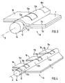
- the flap 7 has a plurality of prepreg strips, which are used to form a loop area 12 laminated to the plane of symmetry of the flap 7 and are then folded together (Fig. 3). The thickness of the flap 7 is thus exposed the sum of the respective thicknesses of the symmetrical partial layers together, which in FIG Reference numerals 7a and 7b are designated. Because of the fold along the The loop area 12, which functions as the flap bearing, is created in the plane of symmetry takes over. Furthermore, in the loop area 12 there is a sliding material 13 (e.g. a PTFE liner) arranged so that the torsion bar 14 inserted into the loop area 12 is as possible is stored without friction and thus reduces wear properties. 3 is located the sliding material 13 on the torsion bar 14.
- a sliding material 13 e.g. a PTFE liner
- the flap 7 made of prepreg material forms the first part of that in FIG. 3 or FIG. 4 shown joint-like connection 10.
- the loop region 12 of the flap 7 has also has a variety of milled out areas, making a variety of individual Loops 12a, 12b etc. remains. It is advantageous here that, in particular, for a Design of the flap in prepreg technology the milling out exactly and consequently with a lot close tolerances is possible.
- the milled out areas create space for Attach a corresponding counterpart to the flap on the pressure side Fasten cover skin.
- the counterpart or the second part of the joint-like Connection 10 is designated by reference numeral 15 in FIG. 3.
- the counterpart is on analogous to the flap-shaped part of the articulation 10 in one piece Design can be produced and has individual fastening loops 16a, 16b etc. at inserted torsion bar 14, the loops are spaced from each other such that Alternate flap loops 12a, 12b etc. and fastening loops 16a, 16b etc.
- the fastening loops 16a, 16b etc. are each in the chamfered areas the flap 7 arranged, as can be seen both in Fig. 4 and in Fig. 5.
- the flap can be pivoted Flap loops 12a, 12b etc., the torsion bar 14 rotatably in the fastening loops 16a, 16b etc. arranged.
- the flap loops 12a, 12b etc. to be non-rotatably connected to the torsion bar 14 and the fastening loops 16a, 16b etc. can be rotatably mounted about the axis of rotation 14 using a sliding material.
- the counterpart 15 is in sections formed as shown in Fig. 4.
- the individual sections are as follows also called fasteners - analogously with reference numerals 15a, 15b and 15c designated.
- This has the advantage of saving weight, without reducing the weight having to forego sufficient rigidity or strength of the structure.
- the counterpart in this embodiment both from fiber composite material also consist of metallic material, because of the sections Design the dimension in the span direction of each individual by folding manufactured fastener are relatively low. This means that at the Production of the counterpart required flipping the danger or that Occurrence of tension and cracks is reduced.
- the Production of the flap 7 due to its extension in the span direction of up to 17 m such a fold along the plane of symmetry with conventional sheets can hardly be reached, so that with the usual metallic materials the required Gap tightness cannot be achieved.
- These milled recesses 17 run in the span direction along the Arching 9.
- the dimensions of the recesses 17 are the corresponding Fastening areas 18 of the fastening elements 15a, 15b, 15c adapted.
- the fastening areas 18 are inserted and with the pressure side Cover skin 4 glued and / or riveted.
- the flap has an integrated articulated connection 10 can be produced using conventional textile technology.
- the flap 7 is in this Embodiment of two different multi-axial couches, namely one unidirectional and a multidirectionally reinforced fabric, preferably one CFRP.
- the layers are superimposed according to the thickness of the flap and sewn, the unidirectional fabric being arranged in the loop area 12.
- This causes a three-dimensional reinforcement of the flap 7 in the loop area 12.
- Furthermore is caused by such an arrangement delamination of the flap 7 in the Avoided symmetry plane starting from the loop area 12.
- a sliding material 13 for example a PTFE liner.
- the inside diameter of the loop area 12 is also here determined by the diameter of a shaped rod after the resin injection is removed.
- the sliding material 13 in turn remains to reduce Frictional forces in the loop area 12.
- this is also Embodiment loops 12a, 12b, 12c milled with high accuracy and analogous to the previously discussed embodiment with a counterpart 15 or Fastening elements 15a, 15b, 15c arranged along a torsion bar 14. It can the counterpart 15 or each individual fastening element 15a, 15b, 15c made of sheet metal, Prepreg material or textile fabric exist.
- the textile technology variant has that Advantage of cheaper production. It also has a low weight and distinguishes itself from the prepreg variant by a reinforcement in the loop area 12 in the thickness direction.
- spherical plain bearings qualified for aviation according to DZ-0396-3 Flap linkage are suitable in principle, but not the ones described above Designs made of fiber composite material are preferable because they are not as high Gap tightness can be achieved.
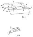
- a joint bearing 25 is shown in Fig. 6.
- the spherical plain bearing has two hinge parts 26, 27.
- One hinge part 26 is e.g. mounted on a flap made of fiber composite material by means of rivets (not shown).
- the other hinge part is e.g. attached to the pressure side cover skin 4.
- the overall height of the spherical bearing is, however, made of fiber composite material larger than the hinge connection 10 integrated in the flap 7.
- the diameter of the conventional spherical plain bearing is typically larger than 12 mm.
- the one shown in FIG. 2 is Trailing edge structure executed in a monolithic construction, which is illustrated in Fig. 5.
- the suction-side cover skin is not shown in FIG. 5 shown.
- the pressure-side cover skin 4 is from the suction-side cover skin 5 via rib-shaped extending in the flow direction Connection elements 19 spaced.
- a connection profile 20 is provided, over which the entire rear edge structure is easily interchangeable.
- the connection profile 20 is for this purpose Detachable rivets on a spar (not shown) of a wing, a landing flap or the like can be removed and installed.
- the rear edge structure including the flap as a unit can be quickly replaced by a suitable replacement part, so that if the flap is damaged, the entire rear edge structure is replaced. In this way it is simple, effective and therefore inexpensive Maintenance possible.
- the actuating lever 21 actuating actuator (not shown), preferably outside the rear edge structure, i.e. arranged within the front profile area 2.
- the pressure-side cover skin 4, the suction-side cover skin 5, the ribs 19 and the connection profile 20 are preferably in for lightning protection reasons Aluminum construction are made.
- the Fiber composite material additionally a copper wire mesh ("copper mesh") and a Ground strap must be laminated.
Landscapes
- Engineering & Computer Science (AREA)
- Mechanical Engineering (AREA)
- Aviation & Aerospace Engineering (AREA)
- Wind Motors (AREA)
- Laminated Bodies (AREA)
- Moulding By Coating Moulds (AREA)
- Lining Or Joining Of Plastics Or The Like (AREA)
- Compositions Of Oxide Ceramics (AREA)
- Outer Garments And Coats (AREA)
- Prostheses (AREA)
Abstract
Description
- Fig. 1
- eine schematische dreidimensionale Ansicht eines gattungsgemäßen aerodynamischen Profils;
- Fig. 2
- eine Schnittansicht des hinteren Profilbereiches des erfindungsgemäßen aerodynamischen Profils;
- Fig. 3
- einen Prinzipaufbau einer Klappe aus Faserverbundwerkstoff mit integrierter Gelenkverbindung;
- Fig. 4
- eine alternative Ausführungsform der Gelenkverbindung gemäß Fig. 3;
- Fig. 5
- eine schematische dreidimensionale Ansicht des in Fig. 2 dargestellten hinteren Profilbereiches; und
- Fig. 6
- ein herkömmliches Gelenklager zur Anbringung der Klappe an der druckseitigen Deckhaut.
Um etwaige Einflüsse der eingefahrenen Klappe 7 auf den Luftwiderstand weiter zu vermindern, ist die druckseitige Deckhaut 4 im Bereich der Klappenanlenkung, d.h. im Übergangsbereich 8a von druckseitiger Deckhaut 4 zur Klappe 7, an die Form der Klappe 7 bzw. deren gelenkartige Verbindung 10 angepasst. Zu diesem Zweck weist die druckseitige Deckhaut 4 zur Aufnahme der Klappe 7 eine in Richtung Profilinneres weisende Einwölbung 9 auf, wobei der vor der Einwölbung 9 liegende Abschnitt 4a der druckseitigen Deckhaut und der - in Strömungsrichtung betrachtet - nach der Einwölbung 9 liegende Abschnitt 4b annähernd parallel zueinander verlaufen. Dabei ist der sich an die Einwölbung 9 in Richtung Hinterkante 6 anschließende Abschnitt 4b, bezogen auf den vor der Einwölbung 9 liegenden Abschnitt 4a, in Richtung Profilinneres versetzt. Auf diese Weise wird ein effektiver Einbau der Klappe bewirkt, so dass sich diese im Ruhezustand an den hinteren Abschnitt 4b der druckseitigen Deckhaut anschmiegt.
Claims (14)
- Aerodynamisches Profil mit verstellbarer Klappe, das einen vorderen Profilbereich (2) sowie einen in der Abströmung liegenden hinteren Profilbereich (3) aufweist und durch eine druckseitige sowie eine saugseitige Deckhaut (4, 5) begrenzt ist, wobei die druckseitige und die saugseitige Deckhaut (4, 5) im hinteren Profilbereich (3) in einer Profilhinterkante (6) zusammenlaufen, dadurch gekennzeichnet, dass im hinteren Profilbereich (3) an der Unterseite der druckseitigen Deckhaut (4) eine Klappe (7) derart schwenkbar gelagert ist, dass die Klappe (7) im Ruhezustand in Strömungsrichtung (Sström) weisend an der Kontur der druckseitigen Deckhaut (4) anliegt und im ausgelenkten Zustand einen Winkel mit der druckseitigen Deckhaut (4) einschließt, wobei in der Klappe (7) eine luftdichte Gelenkverbindung (10) integriert ist, so dass sich im Windschatten der Klappe (7) ein die Strömungsverhältnisse verbesserndes Wirbelsystem ausbildet.
- Aerodynamisches Profil nach Anspruch 1 dadurch gekennzeichnet, dass die druckseitige Deckhaut (4) im Übergangsbereich (8a) zur Klappe (7) eine Einwölbung (9) aufweist, die an die Form der Gelenkverbindung (10) und der Klappe (7) angepasst ist.
- Aerodynamisches Profil nach Anspruch 1, dadurch gekennzeichnet, dass die Klappe (7) aus Faserverbundwerkstoff besteht.
- Aerodynamisches Profil nach einem der Ansprüche 1 bis 3, dadurch gekennzeichnet, dass die Klappe (7) aus einem laminierten, zusammengefalteten Prepreg-Material besteht, wobei entlang der Faltung ein luftdichter Schlaufenbereich (12) ausgebildet ist, in den zur drehbaren Lagerung der Klappe (7) ein Gleitwerkstoff (13) eingebracht und ein Drehstab (14) einführbar ist.
- Aerodynamisches Profil nach einem der Ansprüche 1 bis 3, dadurch gekennzeichnet, dass die Klappe (7) aus unidirektional und multidirektional verstärkten Faserverbund-Gelegen besteht, die derart miteinander vernäht, imprägniert und ausgehärtet sind, dass im Bereich des unidirektionalen Faserverbund-Geleges ein verstärkter luftdichter Schlaufenbereich (12) entsteht, in den zur drehbaren Lagerung der Klappe (7) ein Gleitwerkstoff (13) eingebracht und ein Drehstab (14) einführbar ist.
- Aerodynamisches Profil nach Anspruch 4 oder 5, dadurch gekennzeichnet, dass der Schlaufenbereich (12) ausgefräste Bereiche aufweist, so dass die Klappe (7) eine Vielzahl von einzelnen Schlaufen (12a, 12b, 12c) aufweist, in die der Drehstab (14) einführbar ist.
- Aerodynamisches Profil nach einem der Ansprüche 4 bis 6, dadurch gekennzeichnet, dass an dem Drehstab (14) ferner ein Gegenstück (15; 15a, 15b, 15c) angeordnet ist, das aus Faserverbundwerkstoff, Aluminium oder einem anderen blechförmigen, metallischen Material besteht und Befestigungsschlaufen (16a, 16b, 16c) aufweist, und wobei der Drehstab (14) mit den Befestigungsschlaufen (16a, 16b, 16c) drehfest verbunden ist und mit den Schlaufen (12a, 12b, 12c) der Klappe (7) drehbar gelagert ist, oder umgekehrt.
- Aerodynamisches Profil nach Anspruch 1, dadurch gekennzeichnet, dass in der druckseitigen Deckhaut (4) Aussparungen (17) vorgesehen sind.
- Aerodynamisches Profil nach Anspruch 8, dadurch gekennzeichnet, dass Befestigungsbereiche (18) der Befestigungselemente (15a, 15b, 15c) in die Aussparungen (17) eingeführt und mittels Kleben und/oder Nieten an der druckseitigen Deckhaut (4) angebracht sind.
- Aerodynamisches Profil nach Anspruch 1, dadurch gekennzeichnet, dass zwischen druckseitiger und saugseitiger Deckhaut (4, 5) Verbindungselemente (19) angeordnet sind, wobei die Verbindungselemente (19) rippenförmig ausgebildet und in Strömungsrichtung (Sström) verlaufend oder holmförmig in Spannweitenrichtung angeordnet sind.
- Aerodynamisches Profil nach Anspruch 1, dadurch gekennzeichnet, dass zwischen druckseitiger und saugseitiger Deckhaut (4, 5) ein Anschlußprofil (20) angeordnet ist, über das der hintere Profilbereich (3) an dem vorderen Profilbereich (2) mittels Befestigungsmitteln austauschbar anbringbar ist.
- Aerodynamisches Profil nach einem der vorangegangenen Ansprüche, dadurch gekennzeichnet, dass an der Unterseite der Klappe (7) ein Befestigungsteil (23) vorgesehen ist, an dem ein Stellhebels (21) über eine Gelenkstelle (22) angelenkt ist.
- Aerodynamisches Profil nach einem der vorangegangenen Ansprüche, dadurch gekennzeichnet, dass ein Aktuator vorgesehen ist, der die Klappe (7) über den daran angelenkten Stellhebel (21) betätigt, wobei der Aktuator im vorderen Profilbereich (2) angeordnet ist.
- Aerodynamisches Profil nach einem der vorangegangenen Ansprüche, dadurch gekennzeichnet, dass die druckseitige Deckhaut (4), die saugseitige Deckhaut (5), die Verbindungselemente (19) sowie das Anschlussprofil (20) aus Aluminium bestehen.
Applications Claiming Priority (2)
| Application Number | Priority Date | Filing Date | Title |
|---|---|---|---|
| DE10156733A DE10156733B4 (de) | 2001-11-19 | 2001-11-19 | Aerodynamisches Profil mit verstellbarer Klappe |
| DE10156733 | 2001-11-19 |
Publications (3)
| Publication Number | Publication Date |
|---|---|
| EP1312545A2 true EP1312545A2 (de) | 2003-05-21 |
| EP1312545A3 EP1312545A3 (de) | 2004-03-31 |
| EP1312545B1 EP1312545B1 (de) | 2006-08-30 |
Family
ID=7706229
Family Applications (1)
| Application Number | Title | Priority Date | Filing Date |
|---|---|---|---|
| EP02024866A Expired - Lifetime EP1312545B1 (de) | 2001-11-19 | 2002-11-08 | Aerodynamisches Profil mit verstellbarer Klappe |
Country Status (5)
| Country | Link |
|---|---|
| US (1) | US6863245B2 (de) |
| EP (1) | EP1312545B1 (de) |
| AT (1) | ATE337960T1 (de) |
| DE (2) | DE10156733B4 (de) |
| ES (1) | ES2269586T3 (de) |
Cited By (2)
| Publication number | Priority date | Publication date | Assignee | Title |
|---|---|---|---|---|
| US8925869B2 (en) | 2010-07-26 | 2015-01-06 | Airbus Operations Gmbh | Aerodynamic body with an ancillary flap |
| CN110203389A (zh) * | 2009-06-05 | 2019-09-06 | 威罗门飞行公司 | 飞行器飞行机构和控制方法 |
Families Citing this family (21)
| Publication number | Priority date | Publication date | Assignee | Title |
|---|---|---|---|---|
| DE10207830B4 (de) | 2002-02-25 | 2004-07-01 | Eads Deutschland Gmbh | Linienförmiger, hydraulischer Schwenkantrieb |
| US6843452B1 (en) * | 2003-06-17 | 2005-01-18 | The Boeing Company | Variable trailing edge geometry and spanload control |
| FR2862941B1 (fr) * | 2003-11-27 | 2007-02-23 | Airbus France | Procede permettant d'eviter les vibrations d'une gouverne de direction d'un aeronef et aeronef mettant en oeuvre ce procede |
| DE102004054345B4 (de) * | 2004-11-09 | 2007-11-22 | Eads Deutschland Gmbh | Dreidimensional verstärktes Faserverbundbauteil mit zumindest einem Schlaufenbereich sowie Verfahren zum Herstellen desselben |
| US20070131820A1 (en) * | 2005-12-09 | 2007-06-14 | Sikorsky Aircraft Corporation | Rotorcraft control system and method of using |
| US8915710B2 (en) * | 2005-12-09 | 2014-12-23 | Sikorsky Aircraft Corporation | Brushless direct current (BLDC) motor based linear or rotary actuator for helicopter rotor control |
| US7740205B1 (en) * | 2006-06-06 | 2010-06-22 | Nahas Roger A | Auxiliary wing and flap assembly for an aircraft |
| DE102007012984B4 (de) * | 2007-03-14 | 2018-10-11 | Airbus Helicopters Deutschland GmbH | Verbindungselement zur Kraftübertragung zwischen einem Klappenantrieb und einer an einem Flügel eines Luftfahrzeugs schwenkbeweglich gelagerten Klappe |
| CA2630698A1 (en) * | 2007-05-10 | 2008-11-10 | Mahmoudi Amirhossein | Flap device |
| US7992825B2 (en) * | 2008-07-23 | 2011-08-09 | Airbus Espana, S.L. | Control surface of aircraft |
| DE102008044677B4 (de) * | 2008-08-28 | 2012-03-22 | Eads Deutschland Gmbh | Luftbremse für Flugzeuge |
| DE102009060082A1 (de) | 2009-12-22 | 2011-06-30 | Airbus Operations GmbH, 21129 | Flügelanordnung mit einer verstellbaren Klappe und Verkleidungselement zum Verkleiden eines Klappenverstellmechanismus eines Flügels |
| DE102010032224A1 (de) | 2010-07-26 | 2012-01-26 | Airbus Operations Gmbh | Aerodynamischer Körper mit Zusatzklappe |
| FR2963314B1 (fr) | 2010-07-27 | 2013-06-14 | Airbus Operations Sas | Procede et dispositif d'amenagement d'une soute avionique en pointe-avant d'un aeronef |
| DE102010033639A1 (de) | 2010-08-06 | 2012-02-09 | Airbus Operations Gmbh | Zusatzklappenvorrichtung und aerodynamischer Körper aufweisend eine solche Zusatzklappenvorrichtung |
| EP2514668B1 (de) * | 2011-04-18 | 2016-11-02 | Claverham Limited | Aktive Gurney-Klappe |
| EP2514667B1 (de) | 2011-04-18 | 2015-06-10 | Claverham Limited | Aktive Gurney-Klappe |
| EP2514669B1 (de) | 2011-04-18 | 2014-09-10 | Claverham Limited | Aktive Gurney-Klappe |
| US10619886B2 (en) | 2015-10-01 | 2020-04-14 | Acme Engineering And Manufacturing Corp. | Airfoil damper |
| US20170106970A1 (en) | 2015-10-15 | 2017-04-20 | The Boeing Company | Composite failsafe torque tube |
| US11046420B2 (en) * | 2019-10-23 | 2021-06-29 | The Boeing Company | Trailing edge flap having a waffle grid interior structure |
Citations (1)
| Publication number | Priority date | Publication date | Assignee | Title |
|---|---|---|---|---|
| DE4107556C1 (de) | 1991-03-08 | 1992-05-14 | Deutsche Airbus Gmbh, 2000 Hamburg, De |
Family Cites Families (12)
| Publication number | Priority date | Publication date | Assignee | Title |
|---|---|---|---|---|
| US1729210A (en) * | 1926-03-12 | 1929-09-24 | Nieuportastra Sa | Wing surface used in aeronautics |
| US1822940A (en) * | 1928-08-20 | 1931-09-15 | American Avigation Corp | Wing structure for airplanes |
| US1893065A (en) * | 1931-04-03 | 1933-01-03 | Zap Dev Company | Aircraft and control thereof |
| DE664509C (de) * | 1937-03-02 | 1938-08-30 | Messerschmitt Boelkow Blohm | Einrichtung zum Ausgleich der von Stroemungskraeften herruehrenden, an Rudern auftretenden Drehmomente |
| FR2125111B1 (de) * | 1971-02-11 | 1974-02-15 | Aerospatiale | |
| DE3631320A1 (de) * | 1986-09-15 | 1988-03-24 | Riedelsheimer Hans Joachim | Tragfluegel |
| US5884872A (en) * | 1993-05-26 | 1999-03-23 | The United States Of America As Represented By The Secretary Of The Navy | Oscillating flap lift enhancement device |
| DE19529706C2 (de) * | 1995-08-11 | 2001-08-02 | Deutsch Zentr Luft & Raumfahrt | Flächentragwerk, insbesondere für ein Luftfahrzeug |
| US6220551B1 (en) * | 1998-01-14 | 2001-04-24 | Manuel Munoz Saiz | Flight controls with automatic balance |
| DE19808196C2 (de) * | 1998-02-27 | 2003-06-05 | Eurocopter Deutschland | Rotorblatt für einen Hubschrauber |
| JP2000043796A (ja) * | 1998-07-30 | 2000-02-15 | Japan Aircraft Development Corp | 複合材の翼形構造およびその成形方法 |
| FR2792285B1 (fr) * | 1999-04-16 | 2001-06-08 | Onera (Off Nat Aerospatiale) | Surface aerodynamique d'aeronef a deflecteur de bord de fuite |
-
2001
- 2001-11-19 DE DE10156733A patent/DE10156733B4/de not_active Expired - Fee Related
-
2002
- 2002-11-08 DE DE50207988T patent/DE50207988D1/de not_active Expired - Lifetime
- 2002-11-08 EP EP02024866A patent/EP1312545B1/de not_active Expired - Lifetime
- 2002-11-08 ES ES02024866T patent/ES2269586T3/es not_active Expired - Lifetime
- 2002-11-08 AT AT02024866T patent/ATE337960T1/de not_active IP Right Cessation
- 2002-11-12 US US10/291,750 patent/US6863245B2/en not_active Expired - Lifetime
Patent Citations (1)
| Publication number | Priority date | Publication date | Assignee | Title |
|---|---|---|---|---|
| DE4107556C1 (de) | 1991-03-08 | 1992-05-14 | Deutsche Airbus Gmbh, 2000 Hamburg, De |
Non-Patent Citations (1)
| Title |
|---|
| C.S. JANG, J.C.ROSS, R.M.CUMMINGS: "Computational Evaluation of an Airfoil with a Gurney Flap" |
Cited By (4)
| Publication number | Priority date | Publication date | Assignee | Title |
|---|---|---|---|---|
| CN110203389A (zh) * | 2009-06-05 | 2019-09-06 | 威罗门飞行公司 | 飞行器飞行机构和控制方法 |
| CN110203389B (zh) * | 2009-06-05 | 2023-08-04 | 威罗门飞行公司 | 飞行器飞行机构和控制方法 |
| US8925869B2 (en) | 2010-07-26 | 2015-01-06 | Airbus Operations Gmbh | Aerodynamic body with an ancillary flap |
| DE102010032225B4 (de) * | 2010-07-26 | 2019-10-31 | Airbus Operations Gmbh | Aerodynamischer Körper mit Zusatzklappe |
Also Published As
| Publication number | Publication date |
|---|---|
| US20030102410A1 (en) | 2003-06-05 |
| US6863245B2 (en) | 2005-03-08 |
| ES2269586T3 (es) | 2007-04-01 |
| DE10156733B4 (de) | 2006-04-20 |
| EP1312545A3 (de) | 2004-03-31 |
| DE10156733A1 (de) | 2003-06-05 |
| ATE337960T1 (de) | 2006-09-15 |
| DE50207988D1 (de) | 2006-10-12 |
| EP1312545B1 (de) | 2006-08-30 |
Similar Documents
| Publication | Publication Date | Title |
|---|---|---|
| EP1312545B1 (de) | Aerodynamisches Profil mit verstellbarer Klappe | |
| DE102005027749B4 (de) | Auftriebserhöhende Klappe, insbesondere Nasenklappe, für einen aerodynamisch wirksamen Flügel | |
| EP0857648B1 (de) | Flugzeug für Personen- und/oder Frachttransport | |
| DE69620989T2 (de) | Wirbel erzeugende Vorderkantenklappe für Überschallflugzeuge | |
| DE602004002166T2 (de) | Störklappe und deren Betätigungsverfahren zur Verbesserung der aerodynamischen Güte einer Flügeloberfläche | |
| DE60307951T2 (de) | Verfahren und Vorrichtung zur Steuerung des Luftstroms um eine Tragfläche, welche eine vordere Kantenvorrichtung mit flexibler Strömungsoberfläche aufweist | |
| DE19925560B4 (de) | Zusatzflügel für Hauptflügel von Flugzeugen | |
| DE102008050544A1 (de) | An der Tragfläche eines Flugzeugs angeordneter Vorflügel | |
| DE69206541T2 (de) | Faserverstärkte Steuerfläche mit fokussierter Belastung. | |
| DE102015105298B4 (de) | Flügelstruktur für Flugobjekte und Verfahren zum Austausch einer Flügelvorderkante bei einer Flügelstruktur | |
| DE102007020870A1 (de) | Hochauftriebssystem am Tragflügel eines Flugzeugs | |
| WO2007095931A2 (de) | Aerodynamische klappe eines flugzeugs mit einer den klappenwirbel beeinflussenden vorrichtung | |
| DE102006058650B4 (de) | Tragflügel eines Flugzeugs | |
| EP2712803B1 (de) | Flügelkörper | |
| DE102009050747A1 (de) | Flugzeug mit mindestens zwei Seitenleitwerken in nicht zentraler Anordnung | |
| DE19854741C1 (de) | Keilelement mit dreieckigem Querschnitt zur Befestigung an der Unterseite einer Tragfläche eines Flugzeuges | |
| DE102011084433A1 (de) | Komponente, Verstärkungsbauteil, Strukturanordnung, Luft- oder Raumfahrzeug sowie Verfahren | |
| EP1008515B1 (de) | Spoiler für Tragflächen | |
| DE102016123096B4 (de) | Steuerflächenbauteil für eine Auftriebshilfevorrichtung eines Luftfahrzeugs sowie Herstellungsverfahren hierfür | |
| DE102012102746B4 (de) | Rotorblatt mit adaptivem Vorflügel für eine Windenergieanlage | |
| DE102007024372A1 (de) | Verfahren und Einrichtung zur Lärmreduzierung an einem Hochauftriebssystem am Tragflügel eines Flugzeugs | |
| DE102022124533B4 (de) | Tragflügel oder Höhenleitwerk für ein Flugobjekt | |
| EP2516257B1 (de) | Flügelanordnung mit einer verstellbaren klappe und verkleidungselement zum verkleiden eines klappenverstellmechanismus eines flügels | |
| EP1227035B1 (de) | Einrichtung zum Verbinden beweglicher Teile mit Strukturbauteilen von Flugzeugen od. dgl. | |
| EP0256374B1 (de) | Seitenleitwerk für Flugzeuge mit spreizbaren Ruderklappen |
Legal Events
| Date | Code | Title | Description |
|---|---|---|---|
| PUAI | Public reference made under article 153(3) epc to a published international application that has entered the european phase |
Free format text: ORIGINAL CODE: 0009012 |
|
| AK | Designated contracting states |
Designated state(s): AT BE BG CH CY CZ DE DK EE ES FI FR GB GR IE IT LI LU MC NL PT SE SK TR |
|
| AX | Request for extension of the european patent |
Extension state: AL LT LV MK RO SI |
|
| PUAL | Search report despatched |
Free format text: ORIGINAL CODE: 0009013 |
|
| AK | Designated contracting states |
Kind code of ref document: A3 Designated state(s): AT BE BG CH CY CZ DE DK EE ES FI FR GB GR IE IT LI LU MC NL PT SE SK TR |
|
| AX | Request for extension of the european patent |
Extension state: AL LT LV MK RO SI |
|
| RIC1 | Information provided on ipc code assigned before grant |
Ipc: 7B 64C 9/02 B Ipc: 7B 64C 9/18 A |
|
| 17P | Request for examination filed |
Effective date: 20040910 |
|
| AKX | Designation fees paid |
Designated state(s): AT BE BG CH CY CZ DE DK EE ES FI FR GB GR IE IT LI LU MC NL PT SE SK TR |
|
| 17Q | First examination report despatched |
Effective date: 20041209 |
|
| GRAP | Despatch of communication of intention to grant a patent |
Free format text: ORIGINAL CODE: EPIDOSNIGR1 |
|
| GRAS | Grant fee paid |
Free format text: ORIGINAL CODE: EPIDOSNIGR3 |
|
| RAP1 | Party data changed (applicant data changed or rights of an application transferred) |
Owner name: EADS DEUTSCHLAND GMBH Owner name: AIRBUS DEUTSCHLAND GMBH |
|
| GRAA | (expected) grant |
Free format text: ORIGINAL CODE: 0009210 |
|
| AK | Designated contracting states |
Kind code of ref document: B1 Designated state(s): AT BE BG CH CY CZ DE DK EE ES FI FR GB GR IE IT LI LU MC NL PT SE SK TR |
|
| PG25 | Lapsed in a contracting state [announced via postgrant information from national office to epo] |
Ref country code: IT Free format text: LAPSE BECAUSE OF FAILURE TO SUBMIT A TRANSLATION OF THE DESCRIPTION OR TO PAY THE FEE WITHIN THE PRESCRIBED TIME-LIMIT;WARNING: LAPSES OF ITALIAN PATENTS WITH EFFECTIVE DATE BEFORE 2007 MAY HAVE OCCURRED AT ANY TIME BEFORE 2007. THE CORRECT EFFECTIVE DATE MAY BE DIFFERENT FROM THE ONE RECORDED. Effective date: 20060830 Ref country code: FI Free format text: LAPSE BECAUSE OF FAILURE TO SUBMIT A TRANSLATION OF THE DESCRIPTION OR TO PAY THE FEE WITHIN THE PRESCRIBED TIME-LIMIT Effective date: 20060830 Ref country code: CZ Free format text: LAPSE BECAUSE OF FAILURE TO SUBMIT A TRANSLATION OF THE DESCRIPTION OR TO PAY THE FEE WITHIN THE PRESCRIBED TIME-LIMIT Effective date: 20060830 Ref country code: SK Free format text: LAPSE BECAUSE OF FAILURE TO SUBMIT A TRANSLATION OF THE DESCRIPTION OR TO PAY THE FEE WITHIN THE PRESCRIBED TIME-LIMIT Effective date: 20060830 Ref country code: IE Free format text: LAPSE BECAUSE OF FAILURE TO SUBMIT A TRANSLATION OF THE DESCRIPTION OR TO PAY THE FEE WITHIN THE PRESCRIBED TIME-LIMIT Effective date: 20060830 |
|
| REG | Reference to a national code |
Ref country code: GB Ref legal event code: FG4D Free format text: NOT ENGLISH |
|
| REG | Reference to a national code |
Ref country code: CH Ref legal event code: EP |
|
| REG | Reference to a national code |
Ref country code: IE Ref legal event code: FG4D Free format text: LANGUAGE OF EP DOCUMENT: GERMAN |
|
| REF | Corresponds to: |
Ref document number: 50207988 Country of ref document: DE Date of ref document: 20061012 Kind code of ref document: P |
|
| GBT | Gb: translation of ep patent filed (gb section 77(6)(a)/1977) |
Effective date: 20061002 |
|
| PG25 | Lapsed in a contracting state [announced via postgrant information from national office to epo] |
Ref country code: SE Free format text: LAPSE BECAUSE OF FAILURE TO SUBMIT A TRANSLATION OF THE DESCRIPTION OR TO PAY THE FEE WITHIN THE PRESCRIBED TIME-LIMIT Effective date: 20061130 Ref country code: MC Free format text: LAPSE BECAUSE OF NON-PAYMENT OF DUE FEES Effective date: 20061130 Ref country code: BG Free format text: LAPSE BECAUSE OF FAILURE TO SUBMIT A TRANSLATION OF THE DESCRIPTION OR TO PAY THE FEE WITHIN THE PRESCRIBED TIME-LIMIT Effective date: 20061130 Ref country code: CH Free format text: LAPSE BECAUSE OF NON-PAYMENT OF DUE FEES Effective date: 20061130 Ref country code: LI Free format text: LAPSE BECAUSE OF NON-PAYMENT OF DUE FEES Effective date: 20061130 Ref country code: DK Free format text: LAPSE BECAUSE OF FAILURE TO SUBMIT A TRANSLATION OF THE DESCRIPTION OR TO PAY THE FEE WITHIN THE PRESCRIBED TIME-LIMIT Effective date: 20061130 Ref country code: BE Free format text: LAPSE BECAUSE OF NON-PAYMENT OF DUE FEES Effective date: 20061130 |
|
| ET | Fr: translation filed | ||
| PG25 | Lapsed in a contracting state [announced via postgrant information from national office to epo] |
Ref country code: PT Free format text: LAPSE BECAUSE OF FAILURE TO SUBMIT A TRANSLATION OF THE DESCRIPTION OR TO PAY THE FEE WITHIN THE PRESCRIBED TIME-LIMIT Effective date: 20070212 |
|
| REG | Reference to a national code |
Ref country code: ES Ref legal event code: FG2A Ref document number: 2269586 Country of ref document: ES Kind code of ref document: T3 |
|
| REG | Reference to a national code |
Ref country code: IE Ref legal event code: FD4D |
|
| PLBE | No opposition filed within time limit |
Free format text: ORIGINAL CODE: 0009261 |
|
| STAA | Information on the status of an ep patent application or granted ep patent |
Free format text: STATUS: NO OPPOSITION FILED WITHIN TIME LIMIT |
|
| REG | Reference to a national code |
Ref country code: CH Ref legal event code: PL |
|
| 26N | No opposition filed |
Effective date: 20070531 |
|
| BERE | Be: lapsed |
Owner name: EADS DEUTSCHLAND G.M.B.H. Effective date: 20061130 Owner name: AIRBUS DEUTSCHLAND G.M.B.H. Effective date: 20061130 |
|
| PG25 | Lapsed in a contracting state [announced via postgrant information from national office to epo] |
Ref country code: AT Free format text: LAPSE BECAUSE OF NON-PAYMENT OF DUE FEES Effective date: 20061108 |
|
| PG25 | Lapsed in a contracting state [announced via postgrant information from national office to epo] |
Ref country code: GR Free format text: LAPSE BECAUSE OF FAILURE TO SUBMIT A TRANSLATION OF THE DESCRIPTION OR TO PAY THE FEE WITHIN THE PRESCRIBED TIME-LIMIT Effective date: 20061201 |
|
| PG25 | Lapsed in a contracting state [announced via postgrant information from national office to epo] |
Ref country code: EE Free format text: LAPSE BECAUSE OF FAILURE TO SUBMIT A TRANSLATION OF THE DESCRIPTION OR TO PAY THE FEE WITHIN THE PRESCRIBED TIME-LIMIT Effective date: 20060830 |
|
| PG25 | Lapsed in a contracting state [announced via postgrant information from national office to epo] |
Ref country code: LU Free format text: LAPSE BECAUSE OF NON-PAYMENT OF DUE FEES Effective date: 20061108 Ref country code: TR Free format text: LAPSE BECAUSE OF FAILURE TO SUBMIT A TRANSLATION OF THE DESCRIPTION OR TO PAY THE FEE WITHIN THE PRESCRIBED TIME-LIMIT Effective date: 20060830 |
|
| PG25 | Lapsed in a contracting state [announced via postgrant information from national office to epo] |
Ref country code: CY Free format text: LAPSE BECAUSE OF FAILURE TO SUBMIT A TRANSLATION OF THE DESCRIPTION OR TO PAY THE FEE WITHIN THE PRESCRIBED TIME-LIMIT Effective date: 20060830 |
|
| REG | Reference to a national code |
Ref country code: ES Ref legal event code: PC2A Owner name: AIRBUS OPERATIONS GMBH Effective date: 20110928 |
|
| REG | Reference to a national code |
Ref country code: DE Ref legal event code: R081 Ref document number: 50207988 Country of ref document: DE Owner name: AIRBUS DEFENCE AND SPACE GMBH, DE Free format text: FORMER OWNER: AIRBUS OPERATIONS GMBH, EADS DEUTSCHLAND GMBH, , DE Effective date: 20140819 Ref country code: DE Ref legal event code: R081 Ref document number: 50207988 Country of ref document: DE Owner name: AIRBUS OPERATIONS GMBH, DE Free format text: FORMER OWNER: AIRBUS OPERATIONS GMBH, EADS DEUTSCHLAND GMBH, , DE Effective date: 20140819 Ref country code: DE Ref legal event code: R081 Ref document number: 50207988 Country of ref document: DE Owner name: AIRBUS DEFENCE AND SPACE GMBH, DE Free format text: FORMER OWNERS: AIRBUS OPERATIONS GMBH, 21129 HAMBURG, DE; EADS DEUTSCHLAND GMBH, 85521 OTTOBRUNN, DE Effective date: 20140819 Ref country code: DE Ref legal event code: R081 Ref document number: 50207988 Country of ref document: DE Owner name: AIRBUS OPERATIONS GMBH, DE Free format text: FORMER OWNERS: AIRBUS OPERATIONS GMBH, 21129 HAMBURG, DE; EADS DEUTSCHLAND GMBH, 85521 OTTOBRUNN, DE Effective date: 20140819 |
|
| REG | Reference to a national code |
Ref country code: FR Ref legal event code: PLFP Year of fee payment: 14 |
|
| REG | Reference to a national code |
Ref country code: FR Ref legal event code: PLFP Year of fee payment: 15 |
|
| REG | Reference to a national code |
Ref country code: FR Ref legal event code: PLFP Year of fee payment: 16 |
|
| PGFP | Annual fee paid to national office [announced via postgrant information from national office to epo] |
Ref country code: DE Payment date: 20191121 Year of fee payment: 18 Ref country code: NL Payment date: 20191120 Year of fee payment: 18 |
|
| PGFP | Annual fee paid to national office [announced via postgrant information from national office to epo] |
Ref country code: IT Payment date: 20191128 Year of fee payment: 18 Ref country code: ES Payment date: 20191220 Year of fee payment: 18 Ref country code: FR Payment date: 20191120 Year of fee payment: 18 |
|
| PGFP | Annual fee paid to national office [announced via postgrant information from national office to epo] |
Ref country code: GB Payment date: 20191120 Year of fee payment: 18 |
|
| REG | Reference to a national code |
Ref country code: DE Ref legal event code: R119 Ref document number: 50207988 Country of ref document: DE |
|
| REG | Reference to a national code |
Ref country code: NL Ref legal event code: MM Effective date: 20201201 |
|
| GBPC | Gb: european patent ceased through non-payment of renewal fee |
Effective date: 20201108 |
|
| PG25 | Lapsed in a contracting state [announced via postgrant information from national office to epo] |
Ref country code: NL Free format text: LAPSE BECAUSE OF NON-PAYMENT OF DUE FEES Effective date: 20201201 |
|
| PG25 | Lapsed in a contracting state [announced via postgrant information from national office to epo] |
Ref country code: IT Free format text: LAPSE BECAUSE OF NON-PAYMENT OF DUE FEES Effective date: 20201108 Ref country code: FR Free format text: LAPSE BECAUSE OF NON-PAYMENT OF DUE FEES Effective date: 20201130 |
|
| PG25 | Lapsed in a contracting state [announced via postgrant information from national office to epo] |
Ref country code: GB Free format text: LAPSE BECAUSE OF NON-PAYMENT OF DUE FEES Effective date: 20201108 Ref country code: DE Free format text: LAPSE BECAUSE OF NON-PAYMENT OF DUE FEES Effective date: 20210601 |
|
| REG | Reference to a national code |
Ref country code: ES Ref legal event code: FD2A Effective date: 20220202 |
|
| PG25 | Lapsed in a contracting state [announced via postgrant information from national office to epo] |
Ref country code: ES Free format text: LAPSE BECAUSE OF NON-PAYMENT OF DUE FEES Effective date: 20201109 |