EP1312534A2 - Dispositif pour la détermination de l'angle de braquage d'un volant - Google Patents
Dispositif pour la détermination de l'angle de braquage d'un volant Download PDFInfo
- Publication number
- EP1312534A2 EP1312534A2 EP02090375A EP02090375A EP1312534A2 EP 1312534 A2 EP1312534 A2 EP 1312534A2 EP 02090375 A EP02090375 A EP 02090375A EP 02090375 A EP02090375 A EP 02090375A EP 1312534 A2 EP1312534 A2 EP 1312534A2
- Authority
- EP
- European Patent Office
- Prior art keywords
- gear
- gear elements
- drive element
- steering
- steering angle
- Prior art date
- Legal status (The legal status is an assumption and is not a legal conclusion. Google has not performed a legal analysis and makes no representation as to the accuracy of the status listed.)
- Granted
Links
Images


Classifications
-
- B—PERFORMING OPERATIONS; TRANSPORTING
- B62—LAND VEHICLES FOR TRAVELLING OTHERWISE THAN ON RAILS
- B62D—MOTOR VEHICLES; TRAILERS
- B62D15/00—Steering not otherwise provided for
- B62D15/02—Steering position indicators ; Steering position determination; Steering aids
Definitions
- the invention relates to a device for determining the Steering angle of a steering wheel according to the preamble of the claim 1.
- Such a device comprises a code carrier as well a device for scanning one on the code carrier provided codes when changing the steering angle are moved towards each other, the device for scanning of the code generates an output signal from which the Steering angle can be determined.
- the problem here is that the revolution counter too should be activated when the vehicle electrical system of the corresponding Motor vehicle is switched off. This includes one electronic solution, if not an additional one Battery operation should be used.
- EP 0 853 355 A2 is a single-stage gear solution with an internal gear mounted on the steering axle and an associated external gear known with a different number of teeth are provided.
- the problem underlying the invention is a new device to detect the steering angle of a steering wheel create with the the number of turns of the steering wheel can be determined in a simple manner.
- this problem is created by a device with the features of claim 1 solved.
- the code carrier is replaced by one of two on one common axis axially one behind the other gear elements formed with one by the steering wheel driven drive element are in operative connection and which rotates with each other when the steering angle changes become.
- the solution according to the invention is based on the knowledge of arrangements known in transmission technology, in which two Gear elements arranged coaxially with one another common drive element are operatively connected to Achieving a high translation in a device for Detect the steering angle of a steering wheel. hereby can be determined by the rotation of the corresponding Gear element not only the respective steering angle between 0 ° and 360 °, but especially the number of Turns of the steering wheel based on a defined Determine the zero point position.
- the Steering angle is not simply an angle between 0 ° and 360 ° understood, but the steering angle is considered an absolute Steering angle viewed from a reference position is continuously increased when the steering wheel is turned, about at ten possible turns of a steering wheel between 0 ° and 360 °.
- the device according to the invention is not used first Line for the exact determination of the steering angle between 0 ° and 360 °, but rather to determine the number of Turns of the steering wheel starting from the zero point position. So here it is particularly about determination the absolute steering angle - from the zero point position of the Steering wheel measured continuously - multiples of 360 ° (i.e. complete revolutions) correctly. For the precise determination of the respective steering angle within one revolution (i.e. between 0 ° and 360 ° respectively 360 ° and 720 ° etc.) may be an additional one Steering angle sensor can be used.
- the scanning of the code is arbitrary to one another Movable assemblies understood that due to a relative movement generate an output signal based on which the Extent of the rotational movement of the gear element provided with the code is detectable.
- this particularly simple to implement scanning arrangement can, for example, be based on the Hall effect magnetic measuring principle or one on the scan optical measuring principle based on defined markings be used.
- the solution according to the invention has the advantage that it as one-step solution inexpensive and technically simple is feasible.
- the invention works Device quiet.
- gear elements are particularly suitable gears with at least a counter toothing of the drive element in engagement stand.
- the two gear elements are arranged and trained that when the steering angle changes be rotated at an angle to each other that is significant is smaller than the steering angle, preferably such that the two transmission elements at the maximum possible Change the steering angle (according to the maximum possible Number of turns of the steering wheel) by one angle less than 360 ° to each other.
- the two gear elements are preferably coaxial the steering wheel axle.
- the rotatably mounted gear element serves as a code carrier, i.e. with the one to be scanned Code is provided.
- the required translation can in particular thereby achieved that the two gear elements one have different numbers of teeth, one
- the smallest possible difference in the number of teeth (for example a gear with 50 teeth and a gear with 49 Teeth) is advantageous.
- the drive element that occurs when the steering wheel rotates (corresponding to a change in the steering angle) driven and acts on the two gear elements can in particular be a (about its central axis) act rotatable gear, its diameter is smaller than the diameter of the two gear elements and that with respect to the gear elements a planet gear forms.
- the axis of rotation of the drive element runs when arranged of the two axially arranged transmission elements on the steering axis parallel to this and the drive element has two toothed areas arranged axially one behind the other on, each with one of the two Gear elements is engaged.
- the two toothed areas have the drive element the same shape and number of teeth. However, it can also be designed differently Gear areas with a different number be provided on teeth.
- the two gear elements have each have an external toothing in which the Engages drive element.
- an internal toothing can be used be provided on the two gear elements in which engages the drive element.
- the toothing can be at least one of the two Gear elements along the circumference of the gear element have a variation in the formation of the teeth. This can result in a non-linearity in the translation be achieved. So there is the possibility at the appropriate Gear element to provide blind areas at their Interaction with the drive element no relative movement of the two transmission elements, that is, by the Scanning device also no correspondingly changed Output signals (sensor signals) are generated. So that can the wear of the scanning device, especially when driving straight ahead be minimized. In the borderline case, this embodiment rather a switching of the two Gear elements to each other as a continuous twisting to reach.
- this is Drive element movably mounted so that hereby Tolerances regarding the position of the two on one arranged common axis and with the drive element engaged gear elements balanced can be. Because these gear elements preferably on the steering axis of a steering wheel arrangement are to be arranged, tolerances regarding the arrangement and Training of the steering column of the steering wheel assembly immediately also on the position of said gear elements. Ty-axial tolerances on the order of two millimeters as well as a tilt (impact) of up to two degrees. To compensate for such tolerances in the position of Gear elements is the assigned drive element in radial and / or axial direction movable.
- the solution according to the invention is also characterized by that - in contrast to conventional planetary gears - the Force transmission into the one serving as the steering angle measuring system Transmission takes place via the planet gear as a drive element. Because this turns when the steering wheel turns on a circular path moves whose center through the central axis of the two gear elements interacting with the drive element is formed, the drive element, around rotating its own axis, rolling on the gear elements. As a result, and in particular by collapsing the steering axis with the central axis of the gear elements becomes a particularly simple, compact construction of the transmission made possible with just a few gear elements.
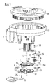
- FIGs 1 to 2c is one in different views Steering angle sensor device for a motor vehicle with a Rotor R and a stator S shown.
- the rotor R is connected to the steering wheel in this way, for example via a Steering spindle that it turns when the steering wheel around the Steering axis L is rotated.
- the stator S is in contrast by means of suitable fastening elements on one Fixed assembly that can be moved together with the steering wheel attached to the motor vehicle.
- the one shown in Figure 1 Rotor-stator arrangement is designed such that it is used for Transmission of electrical signals between rotor R and Stator S is suitable by means of electrical lines extend from the rotor to the stator and which at one Rotary movement are wound up or unwound.
- a such rotor-stator arrangement is for example from the DE 200 07 862 U1 known. This is followed for further Details of the rotor-stator arrangement and in particular their coupling with a steering device in full content Referred.
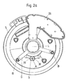
- the device provided for this purpose comprises two coaxially gear wheels 1 arranged one behind the other on the steering axis L, 2 with an annular base body 10, 20 and one each External teeth 11, 12.
- One gear 1 is freely rotatable mounted on the steering axis L and the other gear 2 via a frame G and fastener B rotatably on Stator S set.
- the two gears 1, 2 rotatable relative to one another is a Planet gear 3 assigned, which by means of a bearing pin 35 and a bearing piece 36, which by means of a fastening section 37 radially displaceable with respect to the Steering axis L in a T-groove 38 on the outer edge of the receiving sleeve H is received, rotatable on the outer edge of a receiving sleeve H is mounted, which is firmly connected to the rotor R. is, so it rotates together with this.
- the one provided on the base body 30 of the planetary gear 3 Gear 31 is designed such that they both with the external teeth 11 of the freely rotatable first gear 1 as well as with the external toothing 21 of the second, rotatably mounted gear 2 meshes. This means, that when the steering wheel and thus the Rotors R together with the receiving sleeve H the planet gear 3 with its toothing 31 on the external toothing 11, 21 of the two gears 1, 2 rolls.
- the toothing 31 of the drive gear 3 is, so to speak formed by two axially arranged, identical (and therefore not shown separately in the figures) Gear areas, one of which with the first gear 1 and the second with the second gear 2 is engaged. If necessary, the two gear areas also have different teeth.
- the external gears 11, 21 of the two on the steering axis L Mounted gears 1, 2 preferably have the same or a similar tooth module as the toothing 31 of the Planetary gear 3.
- the offset of the two gears 1, 2 after one revolution the gear can be provided by means of a device provided for this purpose Sensor device 15, 25 are detected; and the like applies to the increasing offset with every further rotation the steering wheel and thus the rotor R, in which the planetary gear 3 is taken along and on the external teeth 11, 21 of the two gear wheels mounted on the steering axle L. 1, 2 rolls.
- the offset of the two gears 1, 2 to each other i.e. the relative rotation of the freely rotatably mounted first gear 1 with respect of the non-rotatably arranged gear 2
- maximum 360 ° or less In this case, everyone can Position of the two gears 1, 2 to each other directly the number of revolutions of the rotor R and thus the Read the steering wheel.
- the resolution within one revolution (corresponding to one Steering angle between 0 ° and 360 °) is therefore smaller, so that for an accurate determination of the steering angle within an additional sensor if necessary must be used.
- the to determine the number of Revolutions provided device can then additionally to monitor this additional sensor using plausibility checks be used.
- the sensor device 15, 25 is in the present case by a Magnet 15 formed, which is ring-like along a Part of the circumference of the first gear 1 extends.
- This magnet 15 generates a magnetic code through an associated magnetic field sensitive and on a Board 26 mounted sensor element 25 can be scanned.
- the Board 26 is attached to an extension F of the stator S, so that the magnetic field-sensitive sensor element 25 is stationary is stored.
- the magnetic field at the location of the sensor element 25 thus depends on the relative position of the magnet 15 bearing first gear 1 with respect to the second gear 2 from. This allows the relative position of the two gears 1, 2 and thus - as explained above - the absolute angle of rotation (including the number of revolutions determine the steering wheel and thus the rotor R).
- the invention differs from that based on the Figures 1 to 2c described essentially by that the rotor-stator arrangement is not used to transmit electrical Signals between the rotor and stator is formed.
- the stator is made by a simple housing, consisting of a lower part U and a cover D, in which the rotor R is rotatably mounted.
- the rotor R on its scope with a means of a detection device E optically scannable coding C is provided. This serves for more precise determination of the steering angle within a Turn of the steering wheel.
- the detection device used here E can be a transmitter in the usual way as well comprise an assigned receiver with which the coding C, for example, in the transmitted light method becomes.
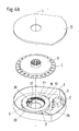
- FIGS. 3a to 3c Exemplary embodiment with the aid of FIGS. 1 to 2c explained so that in this regard to the Reference is made to Figures 1 to 2c.
- FIGS. 4a to 4c shown from Figures 3a to 3c, wherein the only difference is that the two are on the steering axis L coaxially arranged gears 1, 2 each with an internal toothing 12 or 22 are provided and that the toothing 31 of the drive gear 3 accordingly with the internal gears 12, 22 combs.
- the drive gear 3 is within the Ring arranged by the base body 10, 20 of the two coaxially arranged gears 1, 2 is formed.
- Embodiments of the invention is additional for a rough determination of the complete steering angle (over the total number of turns of the steering wheel, that is in particular beyond 360 degrees) by means of the gear wheels 1, 2, 3 still a fine determination of the steering angle during one turn (i.e. between 0 ° and 360 °) by means of of the code C which can be scanned by a detection device E. possible.
- the gears 1, 2, 3 and the associated Sensor device 15 25 generated measurement results the steering angle can in addition to determining the Number of turns of the steering wheel (starting from one Reference position) also for a plausibility check of the determined by the detection device E steering angle serve.
Landscapes
- Engineering & Computer Science (AREA)
- Chemical & Material Sciences (AREA)
- Combustion & Propulsion (AREA)
- Transportation (AREA)
- Mechanical Engineering (AREA)
- Measurement Of Length, Angles, Or The Like Using Electric Or Magnetic Means (AREA)
- Length Measuring Devices With Unspecified Measuring Means (AREA)
- Power Steering Mechanism (AREA)
- Steering Controls (AREA)
- Transmission And Conversion Of Sensor Element Output (AREA)
Applications Claiming Priority (2)
| Application Number | Priority Date | Filing Date | Title |
|---|---|---|---|
| DE10158287 | 2001-11-20 | ||
| DE10158287A DE10158287B4 (de) | 2001-11-20 | 2001-11-20 | Vorrichtung zur Bestimmung des Lenkwinkels eines Lenkrades |
Publications (3)
| Publication Number | Publication Date |
|---|---|
| EP1312534A2 true EP1312534A2 (fr) | 2003-05-21 |
| EP1312534A3 EP1312534A3 (fr) | 2004-03-24 |
| EP1312534B1 EP1312534B1 (fr) | 2006-07-19 |
Family
ID=7707208
Family Applications (1)
| Application Number | Title | Priority Date | Filing Date |
|---|---|---|---|
| EP02090375A Expired - Fee Related EP1312534B1 (fr) | 2001-11-20 | 2002-11-11 | Dispositif pour la détermination de l'angle de braquage d'un volant |
Country Status (5)
| Country | Link |
|---|---|
| US (1) | US20030094054A1 (fr) |
| EP (1) | EP1312534B1 (fr) |
| JP (1) | JP2003214845A (fr) |
| DE (2) | DE10158287B4 (fr) |
| ES (1) | ES2267938T3 (fr) |
Cited By (2)
| Publication number | Priority date | Publication date | Assignee | Title |
|---|---|---|---|---|
| CN101190689B (zh) * | 2006-12-01 | 2010-09-08 | 现代摩比斯株式会社 | 转向角传感器装配装置 |
| CN109398484A (zh) * | 2017-08-18 | 2019-03-01 | 凯尔西-海耶斯公司 | 绝对转向角传感器组件 |
Families Citing this family (7)
| Publication number | Priority date | Publication date | Assignee | Title |
|---|---|---|---|---|
| DE10339963B4 (de) * | 2003-08-26 | 2007-07-26 | Børsting, John | Drehgeber |
| DE102009011352B3 (de) * | 2009-03-05 | 2010-07-15 | Bourns, Inc., Riverside | Torsionswinkelsensor |
| WO2011013217A1 (fr) | 2009-07-29 | 2011-02-03 | トヨタ自動車株式会社 | Système de commande de direction |
| DE112010005795B4 (de) * | 2010-08-05 | 2017-02-23 | Toyota Jidosha Kabushiki Kaisha | Lenksteuervorrichtung |
| DE102012109787B4 (de) * | 2012-10-15 | 2014-05-15 | Takata AG | Lenkwinkelsensor für Kraftfahrzeuge |
| DE102014102982B3 (de) * | 2014-03-06 | 2015-03-05 | Horst Scholz Gmbh & Co. Kg | Lenkwinkelsensor |
| CN109238079B (zh) * | 2018-11-05 | 2020-09-25 | 兰州万里航空机电有限责任公司 | 可调式偏摆仪 |
Citations (2)
| Publication number | Priority date | Publication date | Assignee | Title |
|---|---|---|---|---|
| EP0853355A2 (fr) | 1997-01-14 | 1998-07-15 | Lucas Industries Public Limited Company | Connecteur électrique |
| DE19807522A1 (de) | 1998-02-21 | 1999-03-25 | Bosch Gmbh Robert | Drehwinkel- und Drehzahlsensor |
Family Cites Families (21)
| Publication number | Priority date | Publication date | Assignee | Title |
|---|---|---|---|---|
| JPH0391908U (fr) * | 1989-12-29 | 1991-09-19 | ||
| JPH04325375A (ja) * | 1991-04-25 | 1992-11-13 | Honda Motor Co Ltd | 自動車用舵角センサ |
| DE4115244C2 (de) * | 1991-05-10 | 1998-07-16 | Bayerische Motoren Werke Ag | Winkelsensor zur Bestimmung der Drehlage einer Lenkwelle eines Kraftfahrzeugs |
| US5243188A (en) * | 1991-09-26 | 1993-09-07 | Kabushiki Kaisha Tokai Rika Denki Seisakusho | Neutral position detector for steering wheels having a first and second rotors with aligned slots |
| GB9202868D0 (en) * | 1992-02-12 | 1992-03-25 | Lucas Ind Plc | Optical torque sensors and steering systems for vehicles incorporating them |
| DE4409892A1 (de) * | 1994-03-23 | 1995-09-28 | Bosch Gmbh Robert | Sensor zur Erfassung des Lenkwinkels |
| DE19506938A1 (de) * | 1995-02-28 | 1996-08-29 | Bosch Gmbh Robert | Verfahren und Vorrichtung zur Winkelmessung bei einem drehbaren Körper |
| DE59605586D1 (de) * | 1995-11-17 | 2000-08-17 | Kostal Leopold Gmbh & Co Kg | Winkelsensor |
| DE19601965A1 (de) * | 1996-01-20 | 1997-07-24 | Teves Gmbh Alfred | Lenkwinkelsensor mit Umdrehungszählwerk |
| US6759648B2 (en) * | 1997-08-15 | 2004-07-06 | Bishop Innovation Limited | Sensor for sensing absolute angular position of a rotatable body |
| DE19739823A1 (de) * | 1997-09-11 | 1999-03-18 | Bosch Gmbh Robert | Verfahren und Vorrichtung zur Messung des Winkels eines ersten drehbaren Körpers |
| US6155106A (en) * | 1997-10-29 | 2000-12-05 | Alps Electric Co., Inc. | Steering angle sensor unit |
| JP3612205B2 (ja) * | 1998-02-26 | 2005-01-19 | アルプス電気株式会社 | 結合具、及びこの結合具を使用した回転角度センサ |
| US6248993B1 (en) * | 1998-08-05 | 2001-06-19 | Leopold Kostal Gmbh & Co. Kg | Steering angle sensor |
| JP2000205811A (ja) * | 1999-01-08 | 2000-07-28 | Alps Electric Co Ltd | 回転型センサ |
| DE19902739C2 (de) * | 1999-01-25 | 2001-10-25 | Wolfgang Schleicher | Drehgeber |
| JP3821978B2 (ja) * | 1999-02-22 | 2006-09-13 | アルプス電気株式会社 | 舵角センサユニット |
| DE19942477C2 (de) * | 1999-09-06 | 2001-07-12 | Kostal Leopold Gmbh & Co Kg | Lenkwinkelsensor |
| US6443020B1 (en) * | 2000-09-15 | 2002-09-03 | Delphi Technologies, Inc. | Steering column differential angle position sensor |
| JP2002154440A (ja) * | 2000-11-17 | 2002-05-28 | Yazaki Corp | ステアリング用舵角センサの取付構造 |
| US20030019113A1 (en) * | 2001-07-26 | 2003-01-30 | Valeo Schalter Und Sensoren Gmbh | Steering column module with steering angle sensor having low sensitivity to steering column radial run-out |
-
2001
- 2001-11-20 DE DE10158287A patent/DE10158287B4/de not_active Expired - Fee Related
-
2002
- 2002-11-11 ES ES02090375T patent/ES2267938T3/es not_active Expired - Lifetime
- 2002-11-11 EP EP02090375A patent/EP1312534B1/fr not_active Expired - Fee Related
- 2002-11-11 DE DE50207553T patent/DE50207553D1/de not_active Expired - Fee Related
- 2002-11-18 JP JP2002334424A patent/JP2003214845A/ja active Pending
- 2002-11-20 US US10/299,723 patent/US20030094054A1/en not_active Abandoned
Patent Citations (2)
| Publication number | Priority date | Publication date | Assignee | Title |
|---|---|---|---|---|
| EP0853355A2 (fr) | 1997-01-14 | 1998-07-15 | Lucas Industries Public Limited Company | Connecteur électrique |
| DE19807522A1 (de) | 1998-02-21 | 1999-03-25 | Bosch Gmbh Robert | Drehwinkel- und Drehzahlsensor |
Cited By (3)
| Publication number | Priority date | Publication date | Assignee | Title |
|---|---|---|---|---|
| CN101190689B (zh) * | 2006-12-01 | 2010-09-08 | 现代摩比斯株式会社 | 转向角传感器装配装置 |
| CN109398484A (zh) * | 2017-08-18 | 2019-03-01 | 凯尔西-海耶斯公司 | 绝对转向角传感器组件 |
| CN109398484B (zh) * | 2017-08-18 | 2023-08-08 | 凯尔西-海耶斯公司 | 绝对转向角传感器组件 |
Also Published As
| Publication number | Publication date |
|---|---|
| EP1312534B1 (fr) | 2006-07-19 |
| EP1312534A3 (fr) | 2004-03-24 |
| DE10158287A1 (de) | 2003-06-05 |
| DE10158287B4 (de) | 2006-03-23 |
| ES2267938T3 (es) | 2007-03-16 |
| JP2003214845A (ja) | 2003-07-30 |
| DE50207553D1 (de) | 2006-08-31 |
| US20030094054A1 (en) | 2003-05-22 |
Similar Documents
| Publication | Publication Date | Title |
|---|---|---|
| EP0699151B1 (fr) | Detecteur pour la determination de l'angle de braquage | |
| EP1917167B9 (fr) | Dispositif d'entrainement auxiliaire electromoteur pour des vehicules a moteur | |
| EP2247925B1 (fr) | Dispositif de détection d'un angle de rotation | |
| EP0953494B1 (fr) | Appareil pour détecter une valeur de torsion entre deux pièces | |
| EP1087884B1 (fr) | Direction assistee electriquement pour automobiles | |
| EP0970000B1 (fr) | Systeme de capteur d'angle de braquage a redondance accrue | |
| DE4134794A1 (de) | Weggeber fuer einen stellantrieb, insbesondere in einem fahrzeug | |
| EP1408305A2 (fr) | Dispositif de mesure de l'angle absolu d'un arbre tournant | |
| WO2007087914A1 (fr) | Dispositif d'actionnement, notamment pour un frein de stationnement de véhicule à moteur | |
| DE102020106785A1 (de) | Hinterachslenkung und Lenkwinkelmessung an der Hinterachse eines Kraftfahrzeugs | |
| EP1013534A1 (fr) | Direction assistée électrique en particulier pour véhicules à moteur | |
| EP1312534B1 (fr) | Dispositif pour la détermination de l'angle de braquage d'un volant | |
| DE10329293A1 (de) | Einrichtung zur Erfassung einer Drehbewegung in einer Fahrzeug-Lenkeinrichtung | |
| DE19937222C2 (de) | Steuervorrichtung für einen Elektromotor für ein verstellbares Fahrzeugteil | |
| EP3907473B1 (fr) | Dispositif de mesure d'angle pour une mesure simple tour et multitour | |
| DE19722707C2 (de) | Verfahren und Vorrichtung zum Einbauen von Bauteilen in einen Winkelgeber | |
| DE19653962A1 (de) | Vorrichtung zum Erfassen von Drehmomenten | |
| DE10336853B4 (de) | Drehmomentsensoranordnung für eine Lenksäule | |
| DE10046660C1 (de) | Sensoranordnung zur Erfassung eines Drehwinkels | |
| EP0762015B1 (fr) | Actionneur | |
| DE102020123965B4 (de) | Spindeltriebanordnung, Lenkeinheit und Fahrwerksaktuator | |
| DE19627402A1 (de) | Vorrichtung zur Erfassung der Antriebskraft eines durch Muskelkraft betriebenen Geräts | |
| DE19836666C1 (de) | Lenkwinkelsensor | |
| DE102009002492B4 (de) | Drehwertgeber mit koaxial gelagertem Geberrad | |
| DE102018106006B4 (de) | Lenkwinkelsensor mit Spielausgleich und reduziertem Spiel |
Legal Events
| Date | Code | Title | Description |
|---|---|---|---|
| PUAI | Public reference made under article 153(3) epc to a published international application that has entered the european phase |
Free format text: ORIGINAL CODE: 0009012 |
|
| AK | Designated contracting states |
Designated state(s): AT BE BG CH CY CZ DE DK EE ES FI FR GB GR IE IT LI LU MC NL PT SE SK TR |
|
| AX | Request for extension of the european patent |
Extension state: AL LT LV MK RO SI |
|
| PUAL | Search report despatched |
Free format text: ORIGINAL CODE: 0009013 |
|
| AK | Designated contracting states |
Kind code of ref document: A3 Designated state(s): AT BE BG CH CY CZ DE DK EE ES FI FR GB GR IE IT LI LU MC NL PT SE SK TR |
|
| AX | Request for extension of the european patent |
Extension state: AL LT LV MK RO SI |
|
| RIC1 | Information provided on ipc code assigned before grant |
Ipc: 7B 62D 15/02 A Ipc: 7G 01B 7/30 B |
|
| 17P | Request for examination filed |
Effective date: 20040903 |
|
| AKX | Designation fees paid |
Designated state(s): DE ES FR GB SE |
|
| GRAC | Information related to communication of intention to grant a patent modified |
Free format text: ORIGINAL CODE: EPIDOSCIGR1 |
|
| GRAP | Despatch of communication of intention to grant a patent |
Free format text: ORIGINAL CODE: EPIDOSNIGR1 |
|
| GRAS | Grant fee paid |
Free format text: ORIGINAL CODE: EPIDOSNIGR3 |
|
| GRAA | (expected) grant |
Free format text: ORIGINAL CODE: 0009210 |
|
| AK | Designated contracting states |
Kind code of ref document: B1 Designated state(s): DE ES FR GB SE |
|
| REG | Reference to a national code |
Ref country code: GB Ref legal event code: FG4D Free format text: NOT ENGLISH |
|
| REF | Corresponds to: |
Ref document number: 50207553 Country of ref document: DE Date of ref document: 20060831 Kind code of ref document: P |
|
| REG | Reference to a national code |
Ref country code: SE Ref legal event code: TRGR |
|
| GBT | Gb: translation of ep patent filed (gb section 77(6)(a)/1977) |
Effective date: 20060918 |
|
| ET | Fr: translation filed | ||
| REG | Reference to a national code |
Ref country code: ES Ref legal event code: FG2A Ref document number: 2267938 Country of ref document: ES Kind code of ref document: T3 |
|
| PLBE | No opposition filed within time limit |
Free format text: ORIGINAL CODE: 0009261 |
|
| STAA | Information on the status of an ep patent application or granted ep patent |
Free format text: STATUS: NO OPPOSITION FILED WITHIN TIME LIMIT |
|
| 26N | No opposition filed |
Effective date: 20070420 |
|
| PGFP | Annual fee paid to national office [announced via postgrant information from national office to epo] |
Ref country code: DE Payment date: 20071108 Year of fee payment: 6 Ref country code: ES Payment date: 20071219 Year of fee payment: 6 |
|
| PGFP | Annual fee paid to national office [announced via postgrant information from national office to epo] |
Ref country code: SE Payment date: 20071106 Year of fee payment: 6 |
|
| PGFP | Annual fee paid to national office [announced via postgrant information from national office to epo] |
Ref country code: FR Payment date: 20071108 Year of fee payment: 6 Ref country code: GB Payment date: 20071107 Year of fee payment: 6 |
|
| EUG | Se: european patent has lapsed | ||
| GBPC | Gb: european patent ceased through non-payment of renewal fee |
Effective date: 20081111 |
|
| REG | Reference to a national code |
Ref country code: FR Ref legal event code: ST Effective date: 20090731 |
|
| PG25 | Lapsed in a contracting state [announced via postgrant information from national office to epo] |
Ref country code: DE Free format text: LAPSE BECAUSE OF NON-PAYMENT OF DUE FEES Effective date: 20090603 |
|
| PG25 | Lapsed in a contracting state [announced via postgrant information from national office to epo] |
Ref country code: GB Free format text: LAPSE BECAUSE OF NON-PAYMENT OF DUE FEES Effective date: 20081111 |
|
| REG | Reference to a national code |
Ref country code: ES Ref legal event code: FD2A Effective date: 20081112 |
|
| PG25 | Lapsed in a contracting state [announced via postgrant information from national office to epo] |
Ref country code: ES Free format text: LAPSE BECAUSE OF NON-PAYMENT OF DUE FEES Effective date: 20081112 |
|
| PG25 | Lapsed in a contracting state [announced via postgrant information from national office to epo] |
Ref country code: SE Free format text: LAPSE BECAUSE OF NON-PAYMENT OF DUE FEES Effective date: 20081112 |
|
| PG25 | Lapsed in a contracting state [announced via postgrant information from national office to epo] |
Ref country code: FR Free format text: LAPSE BECAUSE OF NON-PAYMENT OF DUE FEES Effective date: 20081130 |