EP1310596A1 - Procédé de construction d'une voie ferrée sur une dalle de béton et selle provisioire pour la mise en oeuvre de ce procédé - Google Patents
Procédé de construction d'une voie ferrée sur une dalle de béton et selle provisioire pour la mise en oeuvre de ce procédé Download PDFInfo
- Publication number
- EP1310596A1 EP1310596A1 EP02292641A EP02292641A EP1310596A1 EP 1310596 A1 EP1310596 A1 EP 1310596A1 EP 02292641 A EP02292641 A EP 02292641A EP 02292641 A EP02292641 A EP 02292641A EP 1310596 A1 EP1310596 A1 EP 1310596A1
- Authority
- EP
- European Patent Office
- Prior art keywords
- saddles
- temporary
- concrete slab
- concrete
- rails
- Prior art date
- Legal status (The legal status is an assumption and is not a legal conclusion. Google has not performed a legal analysis and makes no representation as to the accuracy of the status listed.)
- Granted
Links
Images


Classifications
-
- E—FIXED CONSTRUCTIONS
- E01—CONSTRUCTION OF ROADS, RAILWAYS, OR BRIDGES
- E01B—PERMANENT WAY; PERMANENT-WAY TOOLS; MACHINES FOR MAKING RAILWAYS OF ALL KINDS
- E01B9/00—Fastening rails on sleepers, or the like
- E01B9/38—Indirect fastening of rails by using tie-plates or chairs; Fastening of rails on the tie-plates or in the chairs
- E01B9/44—Fastening the rail on the tie-plate
-
- E—FIXED CONSTRUCTIONS
- E01—CONSTRUCTION OF ROADS, RAILWAYS, OR BRIDGES
- E01B—PERMANENT WAY; PERMANENT-WAY TOOLS; MACHINES FOR MAKING RAILWAYS OF ALL KINDS
- E01B1/00—Ballastway; Other means for supporting the sleepers or the track; Drainage of the ballastway
- E01B1/002—Ballastless track, e.g. concrete slab trackway, or with asphalt layers
-
- E—FIXED CONSTRUCTIONS
- E01—CONSTRUCTION OF ROADS, RAILWAYS, OR BRIDGES
- E01B—PERMANENT WAY; PERMANENT-WAY TOOLS; MACHINES FOR MAKING RAILWAYS OF ALL KINDS
- E01B29/00—Laying, rebuilding, or taking-up tracks; Tools or machines therefor
- E01B29/005—Making of concrete parts of the track in situ
-
- E—FIXED CONSTRUCTIONS
- E01—CONSTRUCTION OF ROADS, RAILWAYS, OR BRIDGES
- E01B—PERMANENT WAY; PERMANENT-WAY TOOLS; MACHINES FOR MAKING RAILWAYS OF ALL KINDS
- E01B29/00—Laying, rebuilding, or taking-up tracks; Tools or machines therefor
- E01B29/32—Installing or removing track components, not covered by the preceding groups, e.g. sole-plates, rail anchors
-
- E—FIXED CONSTRUCTIONS
- E01—CONSTRUCTION OF ROADS, RAILWAYS, OR BRIDGES
- E01B—PERMANENT WAY; PERMANENT-WAY TOOLS; MACHINES FOR MAKING RAILWAYS OF ALL KINDS
- E01B9/00—Fastening rails on sleepers, or the like
- E01B9/38—Indirect fastening of rails by using tie-plates or chairs; Fastening of rails on the tie-plates or in the chairs
- E01B9/40—Tie-plates for flat-bottom rails
-
- E—FIXED CONSTRUCTIONS
- E01—CONSTRUCTION OF ROADS, RAILWAYS, OR BRIDGES
- E01B—PERMANENT WAY; PERMANENT-WAY TOOLS; MACHINES FOR MAKING RAILWAYS OF ALL KINDS
- E01B2204/00—Characteristics of the track and its foundations
- E01B2204/06—Height or lateral adjustment means or positioning means for slabs, sleepers or rails
-
- E—FIXED CONSTRUCTIONS
- E01—CONSTRUCTION OF ROADS, RAILWAYS, OR BRIDGES
- E01B—PERMANENT WAY; PERMANENT-WAY TOOLS; MACHINES FOR MAKING RAILWAYS OF ALL KINDS
- E01B2204/00—Characteristics of the track and its foundations
- E01B2204/09—Ballastless systems
-
- Y—GENERAL TAGGING OF NEW TECHNOLOGICAL DEVELOPMENTS; GENERAL TAGGING OF CROSS-SECTIONAL TECHNOLOGIES SPANNING OVER SEVERAL SECTIONS OF THE IPC; TECHNICAL SUBJECTS COVERED BY FORMER USPC CROSS-REFERENCE ART COLLECTIONS [XRACs] AND DIGESTS
- Y10—TECHNICAL SUBJECTS COVERED BY FORMER USPC
- Y10T—TECHNICAL SUBJECTS COVERED BY FORMER US CLASSIFICATION
- Y10T29/00—Metal working
- Y10T29/49—Method of mechanical manufacture
- Y10T29/49826—Assembling or joining
- Y10T29/49895—Associating parts by use of aligning means [e.g., use of a drift pin or a "fixture"]
Definitions
- the invention relates to a method for the construction of a railway line and particular to a method of constructing a railway on a concrete slab which the concrete slab is poured around anchoring elements allowing fixation of saddles supporting the tracks of the railway.
- the invention also relates to a temporary saddle used in the method according to the invention.
- an object of the present invention is to provide a method for carrying out of a railroad which ensures the formation without major defects of the bearing surfaces on which are the saddles supporting the rails and which is simple and economical to achieve.
- the subject of the invention is a method of constructing a railway on a concrete slab in which the concrete slab is poured around elements anchoring device for fixing saddles supporting the tracks of the railway.
- the rails are suspended by means of a gantry above where the concrete slab is to be poured, the rails having definitive saddles premounted on the rails, the temporary saddles being placed under these definitive saddles and then brought into the desired position at average of the portico.
- the invention also relates to a temporary saddle intended for the implementation of the method of constructing a railway previously described, characterized in that that it comprises a body whose lower face, intended to be licked by concrete when pouring the concrete slab, is provided with vents.
- Figures 1 and 2 show a temporary saddle 1 according to a particular embodiment of embodiment of the invention.
- the temporary seat 1 comprises a body 11 formed by a rectangular metal plate having multiple vents 10 opening on the lower and upper faces of the plate 11.
- These multiple vents 10 are formed by holes some of which, shown in more detail in FIG. 4, have a circular section slightly convergent, the diameter of these holes 10 being, for example, 7 mm level of the underside of the plate 11 and 5 mm at the level of the face higher.
- the plate 11 also comprises two openings 12 arranged at ends diagonally opposite of the plate 11. These openings 12 receive bushings of 13 having an outside diameter adjusted to the diameter of the opening 12 and an inner bore adapted to fitly receive a threaded rod 4 no shown in Figures 1 and 2.
- the guide bushes 13 comprise in their part lower a shoulder that fits into a cavity adapted to the face lower part of the plate 11 when the sockets 13 are introduced into the openings 12 through the underside of the temporary seat 1.
- Spacers 14 consisting of cylindrical washers, are arranged on the face upper plate 11 around the guide bushes 13, these spacers 14 having an internal bore slightly greater than the outer diameter of the guide sleeves 13.
- the outer periphery of the plate 11 has a step 15 whose edge is beveled towards the underside of the plate 11, the upper edge of the step 15 located on the longitudinal side of the plate 11 being inclined relative to the plane of the underside of the plate 11.
- the temporary seat 1 also has extraction handles 16 facilitating the grasping the temporary saddle 1.
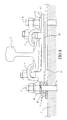
- a gantry 6 is used to bring two rails 2 above the location where a concrete slab 3 is to be poured. These two rails 2 are suspended by clamps 61 connected to a motorized beam 62, the latter sliding vertically on the gantry 6 to precisely bring the two rails 2 to the desired location.
- the two rails 2 are connected to saddles 5 by fasteners 9, these saddles 5 comprising conventional manner a base 51 constituted by a metal plate substantially full intended to rely on the concrete slab 3 via a sole 20, shown in FIG. 8, made of resilient material and advantageously electrically insulating.
- a temporary saddle 1 conforming to that described above is arranged under each of the saddles 5 so that the guide bushes 13 supported by the temporary saddle 1 engage in fitted openings 52 of the base 51, the face bottom of the base 51 coming to bear on the top of the spacers 14 supported by the temporary saddle 1, a resulting space then between the lower face of the base 51 and the upper face of the plate 11 of the temporary seat 1.
- the seat provisional 1 is kept in this position under saddle 5 by the elements anchoring the saddle 5 on the concrete slab 3 constituted here by threaded rods 4 inserted into the guide bushes 13 and receiving in their upper part locking nuts 18, these threaded rods 4 having a local pinch 41 on which rests a washer 17 bearing on the underside of the bushings of 13.
- the threaded rods 4 thus arranged have an overhanging portion largely from the underside of the temporary stool 1 intended to be embedded in the concrete.
- the underside of the stool 1 Prior to the pouring of the concrete slab 3, the underside of the stool 1 is coated with formwork oil and beam 62 of gantry 6 is driven so as to bring the underside of the temporary stool 1 to the place where must be placed the support surfaces of the saddles 5 intended to support the rails 2 of the way to build.
- a concrete slab 3, shown in phantom in FIG. 5, is then cast by gravity up to the height of temporary stool 1 by drowning the part of the stems threaded 4 overflowing under the plate 11. Once this is done, the surface top of the concrete 3 is smoothed so that the surface of the concrete 3 follows the slope walk 15 at the edge of the temporary saddle 1, the latter indicating the slope that the concrete slab 3 must have relative to the horizontal to ensure proper drainage of runoff.
- Electrically insulating spacers 19, shown in FIG. 8, are then disposed within the openings 52 of the saddle 5, these insulating spacers 19 having a body having a cylindrical portion, fitting into the openings 52, whose inner and outer diameters are identical to the inner diameters and outside of the guide bushings 13, that is to say respectively adjusted to the diameter openings 52 and threaded rods 4.
- These spacers 19 also have a flange in the upper part on which the tightening nuts 18 rest, a spring, not shown in the figures, possibly being interposed between the nut and the flange of the spacer 19, the height of the spacer 19 being such that it does not overflow from the underside of the saddle 5 when inserted into the opening 52.
- the rails 2 pre-assembled on their saddles 5 are then lowered again after having inserted the sole 20 of resilient material under the lower face of the base 51, this sole 20 having holes in line with the threaded rods 4.
- An additional sole 21, simply electrically insulating, is advantageously arranged under the previous sole 20, the assembly being brought into contact with the concrete slab 3 while passing the threaded rods 4 projecting from the concrete slab 3 through the soles 20, 21 and bores of the insulating spacers 19 arranged in the openings 52 of the saddles 5 as shown in Figure 8. Due to the presence of spacers insulators 19 with radial dimensions similar to those of guide bushes 13 during this operation, the saddles 5 are then positioned automatically and precisely at their final location.
- the stools 5 are then immobilized in a conventional manner using nuts 18 screwed on the threaded rods 4, the latter bearing on the upper face of the saddle 5 via the collar of the insulating spacer 19.
- Such a construction method, using temporary stools in accordance with the invention makes it possible to obtain easily and rapidly a homogeneous bearing surface for the saddles, which avoids any displacement of the saddles during the tightening of the nuts and ensures stable stool positioning over time.
- the casting of the Concrete slab has the advantage of being carried out without the risk of bubbles appearing of air under the temporary stool because of the many vents that the stool has the latter being not obstructed by the saddle plate thanks to the presence of the spreaders.
Landscapes
- Engineering & Computer Science (AREA)
- Architecture (AREA)
- Civil Engineering (AREA)
- Structural Engineering (AREA)
- Mechanical Engineering (AREA)
- Railway Tracks (AREA)
- Machines For Laying And Maintaining Railways (AREA)
- Forms Removed On Construction Sites Or Auxiliary Members Thereof (AREA)
- On-Site Construction Work That Accompanies The Preparation And Application Of Concrete (AREA)
- Road Paving Structures (AREA)
- Magnetic Heads (AREA)
- Manufacturing Of Tubular Articles Or Embedded Moulded Articles (AREA)
- Moulds, Cores, Or Mandrels (AREA)
- Yarns And Mechanical Finishing Of Yarns Or Ropes (AREA)
Abstract
Description
- maintien en suspension de selles provisoires à l'endroit où devront être placées les selles définitives supportant la voie ferrée, lesdites selles provisoire supportant des éléments d'ancrage destinés à être partiellement noyés dans le béton et comportant des évents permettant l'évacuation de l'air prisonnier sous la face inférieure de la selle provisoire lors du coulage de la dalle de béton,
- coulage d'une dalle de béton jusqu'à hauteur des selles provisoires,
- extraction des selles provisoires après la prise du béton de la dalle,
- mise en place précise des selles définitives supportant les rails dans leur position finale et fixation des selles sur les éléments d'ancrage.
- le corps de la selle provisoire est constituée d'une plaque comportant de multiples trous débouchant ;
- la périphérie de la plaque comporte une marche présentant une arête supérieure qui est inclinée par rapport au plan de la face inférieure de la plaque pour servir de référence lors de la réalisation de la surface de béton de la dalle de voie lorsque celle-ci doit comporter une forme de pente pour en assurer le drainage ;
- le corps de la selle provisoire comporte des ouvertures de diamètre plus important que le diamètre des évents pour permettre le passage des éléments d'ancrage;
- la figure 1 est une vue de dessus, d'une selle provisoire selon un mode particulier de réalisation de l'invention ;
- la figure 2 est une vue de côté de la selle provisoire de la figure 1 ;
- la figure 3 est une vue de détail représentant une coupe de la selle provisoire selon la ligne III-III de la figure 1 ;
- la figure 4 est une vue de détail représentant une coupe de la selle provisoire selon la ligne IV-IV de la figure 1 ;
- la figure 5 est une vue d'ensemble d'un dispositif pour la mise en oeuvre du procédé de construction selon l'invention ;
- la figure 6 est une vue agrandie d'un des rails représentés à la figure 5, ce dernier étant équipé d'une selle provisoire conformément à un mode particulier de réalisation du procédé de construction selon l'invention ;
- la figure 7 est une vue de détail, selon une coupe similaire à celle de la figure 3, des moyens d'assemblage de la selle provisoire sur la selle définitive destinée à supporter le rail ;
- la figure 8 est une vue de coté, avec une coupe partielle, de la selle définitive après son montage sur la dalle de béton.
Claims (6)
- Procédé de construction d'une voie ferrée sur une dalle de béton (3) dans lequel ladite dalle de béton (3) est coulée autour d'éléments d'ancrage (4) permettant la fixation de selles (5) supportant les rails (2) de la voie ferrée, caractérisé en ce qu'il comporte les étapes suivantes :maintien en suspension de selles provisoires (1) à l'endroit où devront être placées les selles (5) supportant la voie ferrée, lesdites selles provisoires (1) supportant des éléments d'ancrage (4) destinés à être partiellement noyés dans le béton (3) et comportant des évents (10) permettant l'évacuation de l'air prisonnier sous la face inférieure de la selle provisoire (1) lors du coulage de la dalle de béton (3),coulage d'une dalle de béton (3) jusqu'à hauteur des selles provisoires (1),extraction des selles provisoires (1) après séchage de la dalle de béton (3),mise en place précise des selles (5) supportant les rails (2) dans leur position finale et fixation des selles (5) sur les éléments d'ancrage (4).
- Procédé de construction d'une voie ferrée selon la revendication 1, caractérisé en ce que lesdits rails (2) sont suspendus au-dessus de l'endroit où la dalle de béton (3) doit être coulée au moyen d'un portique (6), lesdits rails (2) comportant des selles (5) prémontées sur les rails (2) et en ce que lesdites selles provisoires (1) sont disposées sous lesdites selles (5) puis sont amenées dans la position désirée au moyen du portique (6).
- Procédé de construction d'une voie ferrée selon l'une quelconque des revendications 1 à 2, caractérisé en ce que, après l'étape d'extraction des selles provisoires (1) et avant l'étape de mise en place des selles (5), on élimine par raclage les éventuels picots formés à la surface de la dalle de béton (3) par la remonté de béton au travers des évents (10).
- Selle provisoire (1) pour la mise en oeuvre du procédé de construction d'une voie ferrée selon l'une quelconque des revendications 1 à 3, comportant un corps (11) dont la face inférieure est destinée à être léchée par le béton lors de la coulée de la dalle de béton (3), caractérisée en ce que ledit corps est constitué d'une plaque (11) comportant de multiples trous débouchant (10) et en ce que ladite plaque (11) comporte des poignées d'extractions (16).
- Selle provisoire selon la revendication 4, caractérisée la périphérie de la plaque (11) comporte une marche (15) présentant une arête supérieure qui est inclinée par rapport au plan de la face inférieure de la plaque (11).
- Selle provisoire selon l'une quelconque des revendications 4 à 5, caractérisée en ce que ladite plaque (11) comporte des ouvertures (12) de diamètre plus important que le diamètre des évents (10) pour permettre le passage de moyens d'ancrage (4).
Applications Claiming Priority (2)
| Application Number | Priority Date | Filing Date | Title |
|---|---|---|---|
| FR0114401 | 2001-11-07 | ||
| FR0114401A FR2831898B1 (fr) | 2001-11-07 | 2001-11-07 | Procede de construction d'une voie ferree sur une dalle de beton et selle provisoire pour la mise en oeuvre de ce procede |
Publications (2)
| Publication Number | Publication Date |
|---|---|
| EP1310596A1 true EP1310596A1 (fr) | 2003-05-14 |
| EP1310596B1 EP1310596B1 (fr) | 2008-02-20 |
Family
ID=8869150
Family Applications (1)
| Application Number | Title | Priority Date | Filing Date |
|---|---|---|---|
| EP02292641A Expired - Lifetime EP1310596B1 (fr) | 2001-11-07 | 2002-10-24 | Procédé de construction d'une voie ferrée sur une dalle de béton et selle provisioire pour la mise en oeuvre de ce procédé |
Country Status (15)
| Country | Link |
|---|---|
| US (1) | US6732418B2 (fr) |
| EP (1) | EP1310596B1 (fr) |
| JP (1) | JP4102161B2 (fr) |
| KR (1) | KR100918359B1 (fr) |
| AT (1) | ATE386842T1 (fr) |
| BR (1) | BR0204608B1 (fr) |
| CA (1) | CA2410924C (fr) |
| DE (1) | DE60225104T2 (fr) |
| DK (1) | DK1310596T3 (fr) |
| ES (1) | ES2301613T3 (fr) |
| FR (1) | FR2831898B1 (fr) |
| HK (1) | HK1057771A1 (fr) |
| MX (1) | MXPA02010917A (fr) |
| PT (1) | PT1310596E (fr) |
| TW (1) | TWI274094B (fr) |
Cited By (3)
| Publication number | Priority date | Publication date | Assignee | Title |
|---|---|---|---|---|
| WO2006043038A1 (fr) * | 2004-10-19 | 2006-04-27 | Pandrol Limited | Cale de construction de voies de chemin de fer et procede de construction de voies de chemin de fer |
| WO2016146699A1 (fr) | 2015-03-16 | 2016-09-22 | Top-Off Nv | Boîtier pour lit de béton de voie de chemin de fer et procédé pour la construction d'une voie de chemin de fer |
| CN111287028A (zh) * | 2020-02-27 | 2020-06-16 | 中铁第四勘察设计院集团有限公司 | 一种轨道交通 |
Families Citing this family (11)
| Publication number | Priority date | Publication date | Assignee | Title |
|---|---|---|---|---|
| FR2831897B1 (fr) * | 2001-11-07 | 2004-05-28 | Alstom | Procede de construction d'une voie ferree sur une dalle de beton et selle provisoire pour la mise en oeuvre de ce procede |
| FR2833023B1 (fr) * | 2001-12-05 | 2004-05-21 | Alstom | Procede de construction d'une voie ferree dans lequel on realise une dalle de voie en beton et on insere dans la dalle de voie des elements d'ancrage de la voie ferree |
| GR1004786B (el) * | 2003-11-24 | 2005-01-25 | Γεωργιος Ντινοπουλος | Σταθερη επιδομη χωρις στρωτηρες με σκυροδετηση μετα τη ρυθμιση |
| EP1740771B1 (fr) * | 2004-04-29 | 2008-04-16 | Deutsche Gleis-und Tiefbau GmbH | Dispositif d'ajustage pour chassis de voie aiguillages |
| US7766628B2 (en) * | 2006-04-13 | 2010-08-03 | Scroll Technologies | Sealed compressor with structure on lower housing shell to assist weld placement |
| KR100968219B1 (ko) * | 2008-09-24 | 2010-07-06 | 유봉수 | 철도 레일용 침목 |
| HK1134632A2 (en) * | 2008-10-28 | 2010-04-30 | Italian Thai Dev Public Co | Precast track plinth |
| CN103510435A (zh) * | 2012-06-19 | 2014-01-15 | 中铁十九局集团第一工程有限公司 | 一种无砟轨道底座板混凝土浇筑设备 |
| US10081915B2 (en) * | 2016-07-20 | 2018-09-25 | Progress Rail Services Corporation | Track rail fastening mechanism and method |
| US11098454B2 (en) | 2019-04-01 | 2021-08-24 | Progress Rail Services Corporation | Track rail fastener and system for pedestal mounted track rail |
| CN112523009A (zh) * | 2019-09-17 | 2021-03-19 | 洛阳双瑞橡塑科技有限公司 | 一种扣件系统安装结构及施工工艺 |
Citations (3)
| Publication number | Priority date | Publication date | Assignee | Title |
|---|---|---|---|---|
| DE2422942A1 (de) * | 1974-05-11 | 1975-11-20 | Zueblin Ag | Verfahren zur herstellung von eisenbahnoberbauten sowie fertigteile und vorrichtung zur durchfuehrung des verfahrens |
| DE2830137A1 (de) * | 1978-07-08 | 1980-01-17 | Zueblin Ag | Verfahren zur herstellung von gleisoberbauten sowie stahlbetonfertigteile und verlegegeraet zur durchfuehrung des verfahrens |
| US4616395A (en) * | 1983-06-30 | 1986-10-14 | Perini Corporation | Railroad track fixation method and apparatus |
Family Cites Families (8)
| Publication number | Priority date | Publication date | Assignee | Title |
|---|---|---|---|---|
| US4255104A (en) * | 1979-02-16 | 1981-03-10 | Martin Concrete Engineering Company | System for casting and handling concrete railroad ties |
| DE3042725A1 (de) * | 1980-11-13 | 1982-06-16 | Ed. Züblin AG, 7000 Stuttgart | Verfahren zur herstellung einer elastisch gelagerten, schotterlosen oberbaukonstruktion fuer schienenbahnen |
| GB2175635B (en) * | 1985-05-28 | 1988-06-08 | Kumagai Gumi Co Ltd | Formwork |
| US5160084A (en) * | 1987-12-03 | 1992-11-03 | Kerr-Mcgee Corporation | Method for adhesively bonding a rail-tie fastening assembly to a wooden railway tie |
| EP0718438A1 (fr) * | 1994-12-22 | 1996-06-26 | Heilit & Woerner Bau-AG | Superstructure de voie ferrée comprenant une dalle porteuse continue et des dispositifs de fixation individuels pour les rails |
| DE19548229C5 (de) * | 1995-12-22 | 2005-11-24 | intermetric Gesellschaft für Ingenieurmessung und raumbezogene Informationssysteme mbH | Verfahren zum räumlich genauen Positionieren von Fertigungsvorrichtungen und Vorrichtung zum Durchführen des Verfahrens |
| DE10046479B4 (de) * | 2000-09-20 | 2004-05-27 | Pfleiderer Infrastrukturtechnik Gmbh & Co. Kg | Zweiblockbetonschwelle für feste Schienenfahrbahn |
| KR200244844Y1 (ko) * | 2001-05-28 | 2001-10-15 | 공강주 | 체결수단을 이용한 플레이트 |
-
2001
- 2001-11-07 FR FR0114401A patent/FR2831898B1/fr not_active Expired - Fee Related
-
2002
- 2002-10-24 US US10/278,980 patent/US6732418B2/en not_active Expired - Lifetime
- 2002-10-24 DK DK02292641T patent/DK1310596T3/da active
- 2002-10-24 EP EP02292641A patent/EP1310596B1/fr not_active Expired - Lifetime
- 2002-10-24 ES ES02292641T patent/ES2301613T3/es not_active Expired - Lifetime
- 2002-10-24 AT AT02292641T patent/ATE386842T1/de not_active IP Right Cessation
- 2002-10-24 DE DE60225104T patent/DE60225104T2/de not_active Expired - Lifetime
- 2002-10-24 PT PT02292641T patent/PT1310596E/pt unknown
- 2002-11-01 TW TW091132438A patent/TWI274094B/zh not_active IP Right Cessation
- 2002-11-04 CA CA2410924A patent/CA2410924C/fr not_active Expired - Fee Related
- 2002-11-04 KR KR1020020067702A patent/KR100918359B1/ko not_active IP Right Cessation
- 2002-11-04 BR BRPI0204608-3A patent/BR0204608B1/pt not_active IP Right Cessation
- 2002-11-05 JP JP2002320769A patent/JP4102161B2/ja not_active Expired - Fee Related
- 2002-11-06 MX MXPA02010917A patent/MXPA02010917A/es active IP Right Grant
-
2003
- 2003-11-14 HK HK03108331.8A patent/HK1057771A1/xx not_active IP Right Cessation
Patent Citations (3)
| Publication number | Priority date | Publication date | Assignee | Title |
|---|---|---|---|---|
| DE2422942A1 (de) * | 1974-05-11 | 1975-11-20 | Zueblin Ag | Verfahren zur herstellung von eisenbahnoberbauten sowie fertigteile und vorrichtung zur durchfuehrung des verfahrens |
| DE2830137A1 (de) * | 1978-07-08 | 1980-01-17 | Zueblin Ag | Verfahren zur herstellung von gleisoberbauten sowie stahlbetonfertigteile und verlegegeraet zur durchfuehrung des verfahrens |
| US4616395A (en) * | 1983-06-30 | 1986-10-14 | Perini Corporation | Railroad track fixation method and apparatus |
Cited By (3)
| Publication number | Priority date | Publication date | Assignee | Title |
|---|---|---|---|---|
| WO2006043038A1 (fr) * | 2004-10-19 | 2006-04-27 | Pandrol Limited | Cale de construction de voies de chemin de fer et procede de construction de voies de chemin de fer |
| WO2016146699A1 (fr) | 2015-03-16 | 2016-09-22 | Top-Off Nv | Boîtier pour lit de béton de voie de chemin de fer et procédé pour la construction d'une voie de chemin de fer |
| CN111287028A (zh) * | 2020-02-27 | 2020-06-16 | 中铁第四勘察设计院集团有限公司 | 一种轨道交通 |
Also Published As
| Publication number | Publication date |
|---|---|
| MXPA02010917A (es) | 2004-07-16 |
| US6732418B2 (en) | 2004-05-11 |
| CA2410924A1 (fr) | 2003-05-07 |
| KR20030038406A (ko) | 2003-05-16 |
| US20030084558A1 (en) | 2003-05-08 |
| DE60225104T2 (de) | 2009-02-12 |
| EP1310596B1 (fr) | 2008-02-20 |
| TWI274094B (en) | 2007-02-21 |
| PT1310596E (pt) | 2008-07-10 |
| JP2003184009A (ja) | 2003-07-03 |
| CA2410924C (fr) | 2010-02-09 |
| FR2831898A1 (fr) | 2003-05-09 |
| BR0204608A (pt) | 2003-09-16 |
| ES2301613T3 (es) | 2008-07-01 |
| FR2831898B1 (fr) | 2004-10-01 |
| KR100918359B1 (ko) | 2009-09-22 |
| JP4102161B2 (ja) | 2008-06-18 |
| HK1057771A1 (en) | 2004-04-16 |
| BR0204608B1 (pt) | 2012-11-27 |
| DK1310596T3 (da) | 2008-06-02 |
| TW200300194A (en) | 2003-05-16 |
| ATE386842T1 (de) | 2008-03-15 |
| DE60225104D1 (de) | 2008-04-03 |
Similar Documents
| Publication | Publication Date | Title |
|---|---|---|
| EP1310594B1 (fr) | Procédé de construction d'une voie ferrée sur une dalle de béton et selle provisoire pour la mise en oeuvre de ce procédé | |
| EP1310596B1 (fr) | Procédé de construction d'une voie ferrée sur une dalle de béton et selle provisioire pour la mise en oeuvre de ce procédé | |
| FR2746120A1 (fr) | Glissiere de securite, procede de mise en place de telle glissiere et machine de mise en oeuvre de ce procede | |
| EP0939164B1 (fr) | Procédé de construction d'une voie de chemin de fer | |
| EP1381738B1 (fr) | Equipement de voirie pret a l'installation et procede d'installation correspondant | |
| FR2584112A1 (fr) | Dispositif de securite pour bordure de voie de circulation | |
| WO2022101871A1 (fr) | Système de coulissement et de serrage / desserrage pour un armement de support d'une caténaire et procédé d'installation d'un tel système | |
| EP0285492B1 (fr) | Véhicule ferroviaire pour la pose de voies | |
| FR2896519A1 (fr) | "longrine prefabriquee en beton arme precontraint pour rail d'une voie ferree et procede de mise en place" | |
| FR2756507A1 (fr) | Dispositif automatise de maintien d'elements en bois sur une table de pressage en vue de leur assemblage | |
| EP3619379B1 (fr) | Ensemble d'elements de structure destines a former un parking aerien a etages, et parking aerien a etages correspondant | |
| EP0145609B1 (fr) | Platelage de passage à niveau | |
| FR3025813A1 (fr) | Selle de support de rail de voie ferree | |
| FR3011616A1 (fr) | Systeme et procede de fixation d'un dispositif d'eclairage par bridage sur une poutrelle | |
| EP2609265B1 (fr) | Mat basculant automatise demontable, a elements assemblables sans outillage | |
| FR3109945A1 (fr) | Dispositif de fixation d’un rail | |
| FR2981962A1 (fr) | Sabot de garde-corps a collerette d'etancheite | |
| EP0794303A1 (fr) | Procédé et dispositif de fixation au sol d'un élément de mobilier urbain et cabine téléphonique comprenant un tel dispositif | |
| FR2838146A1 (fr) | Abri pour conteneur ou benne de recuperation de dechets | |
| FR2851780A1 (fr) | Longeron prefabrique de pont, ensemble de positionnement relatif de deux longerons et moyen de liaison de feux longerons | |
| FR3135470A3 (fr) | Élément d’ancrage au sol pour le soubassement d’un petit bâtiment. | |
| FR2532039A1 (fr) | Support de projecteur destine a etre place sur les toits-terrasse d'immeubles | |
| FR2527676A1 (fr) | Dispositif de fixation de banches ou de coffrages lors de leur stockage ou de leur mise en place | |
| FR2785932A1 (fr) | Support en beton ou similaire pour ligne electrique aerienne ou analogue | |
| FR3074508A1 (fr) | Systeme d'aide a la pose d'un element de plancher tel qu'une dalle et procedes de pose d'un element de plancher a l'aide de ce systeme |
Legal Events
| Date | Code | Title | Description |
|---|---|---|---|
| PUAI | Public reference made under article 153(3) epc to a published international application that has entered the european phase |
Free format text: ORIGINAL CODE: 0009012 |
|
| AK | Designated contracting states |
Designated state(s): AT BE BG CH CY CZ DE DK EE ES FI FR GB GR IE IT LI LU MC NL PT SE SK TR |
|
| AX | Request for extension of the european patent |
Extension state: AL LT LV MK RO SI |
|
| 17P | Request for examination filed |
Effective date: 20031114 |
|
| AKX | Designation fees paid |
Designated state(s): AT BE BG CH CY CZ DE DK EE ES FI FR GB GR IE IT LI LU MC NL PT SE SK TR |
|
| RAP1 | Party data changed (applicant data changed or rights of an application transferred) |
Owner name: ALSTOM |
|
| GRAP | Despatch of communication of intention to grant a patent |
Free format text: ORIGINAL CODE: EPIDOSNIGR1 |
|
| GRAS | Grant fee paid |
Free format text: ORIGINAL CODE: EPIDOSNIGR3 |
|
| GRAA | (expected) grant |
Free format text: ORIGINAL CODE: 0009210 |
|
| AK | Designated contracting states |
Kind code of ref document: B1 Designated state(s): AT BE BG CH CY CZ DE DK EE ES FI FR GB GR IE IT LI LU MC NL PT SE SK TR |
|
| REG | Reference to a national code |
Ref country code: GB Ref legal event code: FG4D Free format text: NOT ENGLISH |
|
| REG | Reference to a national code |
Ref country code: CH Ref legal event code: EP |
|
| REG | Reference to a national code |
Ref country code: IE Ref legal event code: FG4D Free format text: LANGUAGE OF EP DOCUMENT: FRENCH |
|
| REF | Corresponds to: |
Ref document number: 60225104 Country of ref document: DE Date of ref document: 20080403 Kind code of ref document: P |
|
| REG | Reference to a national code |
Ref country code: DK Ref legal event code: T3 |
|
| REG | Reference to a national code |
Ref country code: SE Ref legal event code: TRGR |
|
| REG | Reference to a national code |
Ref country code: GR Ref legal event code: EP Ref document number: 20080401208 Country of ref document: GR |
|
| REG | Reference to a national code |
Ref country code: ES Ref legal event code: FG2A Ref document number: 2301613 Country of ref document: ES Kind code of ref document: T3 |
|
| REG | Reference to a national code |
Ref country code: PT Ref legal event code: SC4A Free format text: AVAILABILITY OF NATIONAL TRANSLATION Effective date: 20080516 |
|
| RAP2 | Party data changed (patent owner data changed or rights of a patent transferred) |
Owner name: ALSTOM TRANSPORT SA |
|
| NLT2 | Nl: modifications (of names), taken from the european patent patent bulletin |
Owner name: ALSTOM TRANSPORT SA Effective date: 20080806 |
|
| PG25 | Lapsed in a contracting state [announced via postgrant information from national office to epo] |
Ref country code: SK Free format text: LAPSE BECAUSE OF FAILURE TO SUBMIT A TRANSLATION OF THE DESCRIPTION OR TO PAY THE FEE WITHIN THE PRESCRIBED TIME-LIMIT Effective date: 20080220 |
|
| PLBE | No opposition filed within time limit |
Free format text: ORIGINAL CODE: 0009261 |
|
| STAA | Information on the status of an ep patent application or granted ep patent |
Free format text: STATUS: NO OPPOSITION FILED WITHIN TIME LIMIT |
|
| 26N | No opposition filed |
Effective date: 20081121 |
|
| PGFP | Annual fee paid to national office [announced via postgrant information from national office to epo] |
Ref country code: IE Payment date: 20081023 Year of fee payment: 7 |
|
| REG | Reference to a national code |
Ref country code: HK Ref legal event code: GR Ref document number: 1057771 Country of ref document: HK |
|
| BERE | Be: lapsed |
Owner name: ALSTOM Effective date: 20081031 |
|
| PG25 | Lapsed in a contracting state [announced via postgrant information from national office to epo] |
Ref country code: EE Free format text: LAPSE BECAUSE OF FAILURE TO SUBMIT A TRANSLATION OF THE DESCRIPTION OR TO PAY THE FEE WITHIN THE PRESCRIBED TIME-LIMIT Effective date: 20080220 |
|
| PG25 | Lapsed in a contracting state [announced via postgrant information from national office to epo] |
Ref country code: MC Free format text: LAPSE BECAUSE OF NON-PAYMENT OF DUE FEES Effective date: 20081031 |
|
| REG | Reference to a national code |
Ref country code: CH Ref legal event code: PL |
|
| EUG | Se: european patent has lapsed | ||
| PG25 | Lapsed in a contracting state [announced via postgrant information from national office to epo] |
Ref country code: CY Free format text: LAPSE BECAUSE OF FAILURE TO SUBMIT A TRANSLATION OF THE DESCRIPTION OR TO PAY THE FEE WITHIN THE PRESCRIBED TIME-LIMIT Effective date: 20080220 |
|
| PG25 | Lapsed in a contracting state [announced via postgrant information from national office to epo] |
Ref country code: BE Free format text: LAPSE BECAUSE OF NON-PAYMENT OF DUE FEES Effective date: 20081031 |
|
| PG25 | Lapsed in a contracting state [announced via postgrant information from national office to epo] |
Ref country code: LI Free format text: LAPSE BECAUSE OF NON-PAYMENT OF DUE FEES Effective date: 20081031 Ref country code: CH Free format text: LAPSE BECAUSE OF NON-PAYMENT OF DUE FEES Effective date: 20081031 |
|
| PGFP | Annual fee paid to national office [announced via postgrant information from national office to epo] |
Ref country code: AT Payment date: 20091015 Year of fee payment: 8 Ref country code: DK Payment date: 20091014 Year of fee payment: 8 Ref country code: FI Payment date: 20091015 Year of fee payment: 8 |
|
| PGFP | Annual fee paid to national office [announced via postgrant information from national office to epo] |
Ref country code: NL Payment date: 20091016 Year of fee payment: 8 |
|
| PG25 | Lapsed in a contracting state [announced via postgrant information from national office to epo] |
Ref country code: SE Free format text: LAPSE BECAUSE OF NON-PAYMENT OF DUE FEES Effective date: 20081025 Ref country code: LU Free format text: LAPSE BECAUSE OF NON-PAYMENT OF DUE FEES Effective date: 20081024 |
|
| PG25 | Lapsed in a contracting state [announced via postgrant information from national office to epo] |
Ref country code: IE Free format text: LAPSE BECAUSE OF NON-PAYMENT OF DUE FEES Effective date: 20091026 |
|
| PGFP | Annual fee paid to national office [announced via postgrant information from national office to epo] |
Ref country code: PT Payment date: 20101019 Year of fee payment: 9 |
|
| REG | Reference to a national code |
Ref country code: NL Ref legal event code: V1 Effective date: 20110501 |
|
| REG | Reference to a national code |
Ref country code: DK Ref legal event code: EBP |
|
| PG25 | Lapsed in a contracting state [announced via postgrant information from national office to epo] |
Ref country code: NL Free format text: LAPSE BECAUSE OF NON-PAYMENT OF DUE FEES Effective date: 20110501 Ref country code: AT Free format text: LAPSE BECAUSE OF NON-PAYMENT OF DUE FEES Effective date: 20101024 Ref country code: FI Free format text: LAPSE BECAUSE OF NON-PAYMENT OF DUE FEES Effective date: 20101024 |
|
| PG25 | Lapsed in a contracting state [announced via postgrant information from national office to epo] |
Ref country code: DK Free format text: LAPSE BECAUSE OF NON-PAYMENT OF DUE FEES Effective date: 20101031 |
|
| REG | Reference to a national code |
Ref country code: PT Ref legal event code: MM4A Free format text: LAPSE DUE TO NON-PAYMENT OF FEES Effective date: 20120424 |
|
| PG25 | Lapsed in a contracting state [announced via postgrant information from national office to epo] |
Ref country code: PT Free format text: LAPSE BECAUSE OF NON-PAYMENT OF DUE FEES Effective date: 20120424 |
|
| REG | Reference to a national code |
Ref country code: DE Ref legal event code: R082 Ref document number: 60225104 Country of ref document: DE Representative=s name: TER MEER STEINMEISTER & PARTNER PATENTANWAELTE, DE Ref country code: DE Ref legal event code: R081 Ref document number: 60225104 Country of ref document: DE Owner name: ALSTOM TRANSPORT TECHNOLOGIES, FR Free format text: FORMER OWNER: ALSTOM, LEVALLOIS-PERRET, FR |
|
| REG | Reference to a national code |
Ref country code: FR Ref legal event code: TP Owner name: ALSTOM TRANSPORT TECHNOLOGIES SAS, FR Effective date: 20150818 |
|
| REG | Reference to a national code |
Ref country code: FR Ref legal event code: PLFP Year of fee payment: 14 |
|
| REG | Reference to a national code |
Ref country code: GB Ref legal event code: 732E Free format text: REGISTERED BETWEEN 20151001 AND 20151007 |
|
| REG | Reference to a national code |
Ref country code: GB Ref legal event code: 732E Free format text: REGISTERED BETWEEN 20151119 AND 20151125 |
|
| REG | Reference to a national code |
Ref country code: FR Ref legal event code: PLFP Year of fee payment: 15 |
|
| REG | Reference to a national code |
Ref country code: DE Ref legal event code: R082 Ref document number: 60225104 Country of ref document: DE Representative=s name: TER MEER STEINMEISTER & PARTNER PATENTANWAELTE, DE Ref country code: DE Ref legal event code: R081 Ref document number: 60225104 Country of ref document: DE Owner name: ALSTOM TRANSPORT TECHNOLOGIES, FR Free format text: FORMER OWNER: ALSTOM TRANSPORT TECHNOLOGIES, LEVALLOIS-PERRET, FR |
|
| REG | Reference to a national code |
Ref country code: FR Ref legal event code: PLFP Year of fee payment: 16 |
|
| REG | Reference to a national code |
Ref country code: FR Ref legal event code: CA Effective date: 20180103 |
|
| REG | Reference to a national code |
Ref country code: FR Ref legal event code: PLFP Year of fee payment: 17 |
|
| PGFP | Annual fee paid to national office [announced via postgrant information from national office to epo] |
Ref country code: CZ Payment date: 20190925 Year of fee payment: 18 |
|
| PGFP | Annual fee paid to national office [announced via postgrant information from national office to epo] |
Ref country code: DE Payment date: 20191021 Year of fee payment: 18 Ref country code: BG Payment date: 20191023 Year of fee payment: 18 |
|
| PGFP | Annual fee paid to national office [announced via postgrant information from national office to epo] |
Ref country code: GR Payment date: 20191022 Year of fee payment: 18 Ref country code: IT Payment date: 20191028 Year of fee payment: 18 Ref country code: ES Payment date: 20191122 Year of fee payment: 18 Ref country code: FR Payment date: 20191028 Year of fee payment: 18 |
|
| PGFP | Annual fee paid to national office [announced via postgrant information from national office to epo] |
Ref country code: TR Payment date: 20191021 Year of fee payment: 18 |
|
| PGFP | Annual fee paid to national office [announced via postgrant information from national office to epo] |
Ref country code: GB Payment date: 20191021 Year of fee payment: 18 |
|
| REG | Reference to a national code |
Ref country code: DE Ref legal event code: R119 Ref document number: 60225104 Country of ref document: DE |
|
| GBPC | Gb: european patent ceased through non-payment of renewal fee |
Effective date: 20201024 |
|
| PG25 | Lapsed in a contracting state [announced via postgrant information from national office to epo] |
Ref country code: FR Free format text: LAPSE BECAUSE OF NON-PAYMENT OF DUE FEES Effective date: 20201031 Ref country code: GR Free format text: LAPSE BECAUSE OF NON-PAYMENT OF DUE FEES Effective date: 20210510 Ref country code: BG Free format text: LAPSE BECAUSE OF NON-PAYMENT OF DUE FEES Effective date: 20210430 Ref country code: CZ Free format text: LAPSE BECAUSE OF NON-PAYMENT OF DUE FEES Effective date: 20201024 Ref country code: DE Free format text: LAPSE BECAUSE OF NON-PAYMENT OF DUE FEES Effective date: 20210501 |
|
| PG25 | Lapsed in a contracting state [announced via postgrant information from national office to epo] |
Ref country code: GB Free format text: LAPSE BECAUSE OF NON-PAYMENT OF DUE FEES Effective date: 20201024 |
|
| PG25 | Lapsed in a contracting state [announced via postgrant information from national office to epo] |
Ref country code: IT Free format text: LAPSE BECAUSE OF NON-PAYMENT OF DUE FEES Effective date: 20201024 |
|
| REG | Reference to a national code |
Ref country code: ES Ref legal event code: FD2A Effective date: 20220128 |
|
| PG25 | Lapsed in a contracting state [announced via postgrant information from national office to epo] |
Ref country code: ES Free format text: LAPSE BECAUSE OF NON-PAYMENT OF DUE FEES Effective date: 20201025 |
|
| PG25 | Lapsed in a contracting state [announced via postgrant information from national office to epo] |
Ref country code: TR Free format text: LAPSE BECAUSE OF NON-PAYMENT OF DUE FEES Effective date: 20201024 |