EP1309397B1 - Mikroreaktoranordnung zur festphasengestützten synthese sowie mikroreaktorsystem mit einzelnen mikroreaktoranordnungen - Google Patents
Mikroreaktoranordnung zur festphasengestützten synthese sowie mikroreaktorsystem mit einzelnen mikroreaktoranordnungen Download PDFInfo
- Publication number
- EP1309397B1 EP1309397B1 EP01969323A EP01969323A EP1309397B1 EP 1309397 B1 EP1309397 B1 EP 1309397B1 EP 01969323 A EP01969323 A EP 01969323A EP 01969323 A EP01969323 A EP 01969323A EP 1309397 B1 EP1309397 B1 EP 1309397B1
- Authority
- EP
- European Patent Office
- Prior art keywords
- microreactor
- membrane
- reaction chamber
- inlet
- reaction
- Prior art date
- Legal status (The legal status is an assumption and is not a legal conclusion. Google has not performed a legal analysis and makes no representation as to the accuracy of the status listed.)
- Expired - Lifetime
Links
Images

Classifications
-
- B—PERFORMING OPERATIONS; TRANSPORTING
- B01—PHYSICAL OR CHEMICAL PROCESSES OR APPARATUS IN GENERAL
- B01L—CHEMICAL OR PHYSICAL LABORATORY APPARATUS FOR GENERAL USE
- B01L3/00—Containers or dishes for laboratory use, e.g. laboratory glassware; Droppers
- B01L3/50—Containers for the purpose of retaining a material to be analysed, e.g. test tubes
- B01L3/502—Containers for the purpose of retaining a material to be analysed, e.g. test tubes with fluid transport, e.g. in multi-compartment structures
- B01L3/5025—Containers for the purpose of retaining a material to be analysed, e.g. test tubes with fluid transport, e.g. in multi-compartment structures for parallel transport of multiple samples
-
- B—PERFORMING OPERATIONS; TRANSPORTING
- B01—PHYSICAL OR CHEMICAL PROCESSES OR APPARATUS IN GENERAL
- B01F—MIXING, e.g. DISSOLVING, EMULSIFYING OR DISPERSING
- B01F31/00—Mixers with shaking, oscillating, or vibrating mechanisms
- B01F31/30—Mixers with shaking, oscillating, or vibrating mechanisms comprising a receptacle to only a part of which the shaking, oscillating, or vibrating movement is imparted
- B01F31/31—Mixers with shaking, oscillating, or vibrating mechanisms comprising a receptacle to only a part of which the shaking, oscillating, or vibrating movement is imparted using receptacles with deformable parts, e.g. membranes, to which a motion is imparted
-
- B—PERFORMING OPERATIONS; TRANSPORTING
- B01—PHYSICAL OR CHEMICAL PROCESSES OR APPARATUS IN GENERAL
- B01F—MIXING, e.g. DISSOLVING, EMULSIFYING OR DISPERSING
- B01F31/00—Mixers with shaking, oscillating, or vibrating mechanisms
- B01F31/65—Mixers with shaking, oscillating, or vibrating mechanisms the materials to be mixed being directly submitted to a pulsating movement, e.g. by means of an oscillating piston or air column
-
- B—PERFORMING OPERATIONS; TRANSPORTING
- B01—PHYSICAL OR CHEMICAL PROCESSES OR APPARATUS IN GENERAL
- B01F—MIXING, e.g. DISSOLVING, EMULSIFYING OR DISPERSING
- B01F33/00—Other mixers; Mixing plants; Combinations of mixers
- B01F33/30—Micromixers
-
- B—PERFORMING OPERATIONS; TRANSPORTING
- B01—PHYSICAL OR CHEMICAL PROCESSES OR APPARATUS IN GENERAL
- B01F—MIXING, e.g. DISSOLVING, EMULSIFYING OR DISPERSING
- B01F35/00—Accessories for mixers; Auxiliary operations or auxiliary devices; Parts or details of general application
- B01F35/50—Mixing receptacles
- B01F35/514—Mixing receptacles the mixing receptacle or conduit being transparent or comprising transparent parts
-
- B—PERFORMING OPERATIONS; TRANSPORTING
- B01—PHYSICAL OR CHEMICAL PROCESSES OR APPARATUS IN GENERAL
- B01F—MIXING, e.g. DISSOLVING, EMULSIFYING OR DISPERSING
- B01F35/00—Accessories for mixers; Auxiliary operations or auxiliary devices; Parts or details of general application
- B01F35/56—General build-up of the mixers
- B01F35/561—General build-up of the mixers the mixer being built-up from a plurality of modules or stacked plates comprising complete or partial elements of the mixer
-
- B—PERFORMING OPERATIONS; TRANSPORTING
- B01—PHYSICAL OR CHEMICAL PROCESSES OR APPARATUS IN GENERAL
- B01F—MIXING, e.g. DISSOLVING, EMULSIFYING OR DISPERSING
- B01F35/00—Accessories for mixers; Auxiliary operations or auxiliary devices; Parts or details of general application
- B01F35/90—Heating or cooling systems
- B01F35/92—Heating or cooling systems for heating the outside of the receptacle, e.g. heated jackets or burners
-
- B—PERFORMING OPERATIONS; TRANSPORTING
- B01—PHYSICAL OR CHEMICAL PROCESSES OR APPARATUS IN GENERAL
- B01J—CHEMICAL OR PHYSICAL PROCESSES, e.g. CATALYSIS OR COLLOID CHEMISTRY; THEIR RELEVANT APPARATUS
- B01J19/00—Chemical, physical or physico-chemical processes in general; Their relevant apparatus
- B01J19/0046—Sequential or parallel reactions, e.g. for the synthesis of polypeptides or polynucleotides; Apparatus and devices for combinatorial chemistry or for making molecular arrays
-
- B—PERFORMING OPERATIONS; TRANSPORTING
- B01—PHYSICAL OR CHEMICAL PROCESSES OR APPARATUS IN GENERAL
- B01J—CHEMICAL OR PHYSICAL PROCESSES, e.g. CATALYSIS OR COLLOID CHEMISTRY; THEIR RELEVANT APPARATUS
- B01J19/00—Chemical, physical or physico-chemical processes in general; Their relevant apparatus
- B01J19/0093—Microreactors, e.g. miniaturised or microfabricated reactors
-
- B—PERFORMING OPERATIONS; TRANSPORTING
- B01—PHYSICAL OR CHEMICAL PROCESSES OR APPARATUS IN GENERAL
- B01L—CHEMICAL OR PHYSICAL LABORATORY APPARATUS FOR GENERAL USE
- B01L3/00—Containers or dishes for laboratory use, e.g. laboratory glassware; Droppers
- B01L3/50—Containers for the purpose of retaining a material to be analysed, e.g. test tubes
- B01L3/502—Containers for the purpose of retaining a material to be analysed, e.g. test tubes with fluid transport, e.g. in multi-compartment structures
- B01L3/5025—Containers for the purpose of retaining a material to be analysed, e.g. test tubes with fluid transport, e.g. in multi-compartment structures for parallel transport of multiple samples
- B01L3/50255—Multi-well filtration
-
- B—PERFORMING OPERATIONS; TRANSPORTING
- B01—PHYSICAL OR CHEMICAL PROCESSES OR APPARATUS IN GENERAL
- B01J—CHEMICAL OR PHYSICAL PROCESSES, e.g. CATALYSIS OR COLLOID CHEMISTRY; THEIR RELEVANT APPARATUS
- B01J2219/00—Chemical, physical or physico-chemical processes in general; Their relevant apparatus
- B01J2219/00274—Sequential or parallel reactions; Apparatus and devices for combinatorial chemistry or for making arrays; Chemical library technology
- B01J2219/00277—Apparatus
- B01J2219/00279—Features relating to reactor vessels
- B01J2219/00306—Reactor vessels in a multiple arrangement
-
- B—PERFORMING OPERATIONS; TRANSPORTING
- B01—PHYSICAL OR CHEMICAL PROCESSES OR APPARATUS IN GENERAL
- B01J—CHEMICAL OR PHYSICAL PROCESSES, e.g. CATALYSIS OR COLLOID CHEMISTRY; THEIR RELEVANT APPARATUS
- B01J2219/00—Chemical, physical or physico-chemical processes in general; Their relevant apparatus
- B01J2219/00274—Sequential or parallel reactions; Apparatus and devices for combinatorial chemistry or for making arrays; Chemical library technology
- B01J2219/00277—Apparatus
- B01J2219/00279—Features relating to reactor vessels
- B01J2219/00306—Reactor vessels in a multiple arrangement
- B01J2219/00308—Reactor vessels in a multiple arrangement interchangeably mounted in racks or blocks
-
- B—PERFORMING OPERATIONS; TRANSPORTING
- B01—PHYSICAL OR CHEMICAL PROCESSES OR APPARATUS IN GENERAL
- B01J—CHEMICAL OR PHYSICAL PROCESSES, e.g. CATALYSIS OR COLLOID CHEMISTRY; THEIR RELEVANT APPARATUS
- B01J2219/00—Chemical, physical or physico-chemical processes in general; Their relevant apparatus
- B01J2219/00274—Sequential or parallel reactions; Apparatus and devices for combinatorial chemistry or for making arrays; Chemical library technology
- B01J2219/00277—Apparatus
- B01J2219/00279—Features relating to reactor vessels
- B01J2219/00306—Reactor vessels in a multiple arrangement
- B01J2219/00308—Reactor vessels in a multiple arrangement interchangeably mounted in racks or blocks
- B01J2219/0031—Reactor vessels in a multiple arrangement interchangeably mounted in racks or blocks the racks or blocks being mounted in stacked arrangements
-
- B—PERFORMING OPERATIONS; TRANSPORTING
- B01—PHYSICAL OR CHEMICAL PROCESSES OR APPARATUS IN GENERAL
- B01J—CHEMICAL OR PHYSICAL PROCESSES, e.g. CATALYSIS OR COLLOID CHEMISTRY; THEIR RELEVANT APPARATUS
- B01J2219/00—Chemical, physical or physico-chemical processes in general; Their relevant apparatus
- B01J2219/00274—Sequential or parallel reactions; Apparatus and devices for combinatorial chemistry or for making arrays; Chemical library technology
- B01J2219/00277—Apparatus
- B01J2219/00351—Means for dispensing and evacuation of reagents
- B01J2219/00389—Feeding through valves
- B01J2219/00396—Membrane valves
-
- B—PERFORMING OPERATIONS; TRANSPORTING
- B01—PHYSICAL OR CHEMICAL PROCESSES OR APPARATUS IN GENERAL
- B01J—CHEMICAL OR PHYSICAL PROCESSES, e.g. CATALYSIS OR COLLOID CHEMISTRY; THEIR RELEVANT APPARATUS
- B01J2219/00—Chemical, physical or physico-chemical processes in general; Their relevant apparatus
- B01J2219/00274—Sequential or parallel reactions; Apparatus and devices for combinatorial chemistry or for making arrays; Chemical library technology
- B01J2219/00277—Apparatus
- B01J2219/00351—Means for dispensing and evacuation of reagents
- B01J2219/00389—Feeding through valves
- B01J2219/00396—Membrane valves
- B01J2219/00398—Membrane valves in multiple arrangements
-
- B—PERFORMING OPERATIONS; TRANSPORTING
- B01—PHYSICAL OR CHEMICAL PROCESSES OR APPARATUS IN GENERAL
- B01J—CHEMICAL OR PHYSICAL PROCESSES, e.g. CATALYSIS OR COLLOID CHEMISTRY; THEIR RELEVANT APPARATUS
- B01J2219/00—Chemical, physical or physico-chemical processes in general; Their relevant apparatus
- B01J2219/00274—Sequential or parallel reactions; Apparatus and devices for combinatorial chemistry or for making arrays; Chemical library technology
- B01J2219/00277—Apparatus
- B01J2219/00351—Means for dispensing and evacuation of reagents
- B01J2219/00423—Means for dispensing and evacuation of reagents using filtration, e.g. through porous frits
-
- B—PERFORMING OPERATIONS; TRANSPORTING
- B01—PHYSICAL OR CHEMICAL PROCESSES OR APPARATUS IN GENERAL
- B01J—CHEMICAL OR PHYSICAL PROCESSES, e.g. CATALYSIS OR COLLOID CHEMISTRY; THEIR RELEVANT APPARATUS
- B01J2219/00—Chemical, physical or physico-chemical processes in general; Their relevant apparatus
- B01J2219/00274—Sequential or parallel reactions; Apparatus and devices for combinatorial chemistry or for making arrays; Chemical library technology
- B01J2219/00277—Apparatus
- B01J2219/00479—Means for mixing reactants or products in the reaction vessels
- B01J2219/00484—Means for mixing reactants or products in the reaction vessels by shaking, vibrating or oscillating of the reaction vessels
-
- B—PERFORMING OPERATIONS; TRANSPORTING
- B01—PHYSICAL OR CHEMICAL PROCESSES OR APPARATUS IN GENERAL
- B01J—CHEMICAL OR PHYSICAL PROCESSES, e.g. CATALYSIS OR COLLOID CHEMISTRY; THEIR RELEVANT APPARATUS
- B01J2219/00—Chemical, physical or physico-chemical processes in general; Their relevant apparatus
- B01J2219/00274—Sequential or parallel reactions; Apparatus and devices for combinatorial chemistry or for making arrays; Chemical library technology
- B01J2219/00277—Apparatus
- B01J2219/00497—Features relating to the solid phase supports
- B01J2219/005—Beads
-
- B—PERFORMING OPERATIONS; TRANSPORTING
- B01—PHYSICAL OR CHEMICAL PROCESSES OR APPARATUS IN GENERAL
- B01J—CHEMICAL OR PHYSICAL PROCESSES, e.g. CATALYSIS OR COLLOID CHEMISTRY; THEIR RELEVANT APPARATUS
- B01J2219/00—Chemical, physical or physico-chemical processes in general; Their relevant apparatus
- B01J2219/00274—Sequential or parallel reactions; Apparatus and devices for combinatorial chemistry or for making arrays; Chemical library technology
- B01J2219/00583—Features relative to the processes being carried out
- B01J2219/00585—Parallel processes
-
- B—PERFORMING OPERATIONS; TRANSPORTING
- B01—PHYSICAL OR CHEMICAL PROCESSES OR APPARATUS IN GENERAL
- B01J—CHEMICAL OR PHYSICAL PROCESSES, e.g. CATALYSIS OR COLLOID CHEMISTRY; THEIR RELEVANT APPARATUS
- B01J2219/00—Chemical, physical or physico-chemical processes in general; Their relevant apparatus
- B01J2219/00274—Sequential or parallel reactions; Apparatus and devices for combinatorial chemistry or for making arrays; Chemical library technology
- B01J2219/00583—Features relative to the processes being carried out
- B01J2219/0059—Sequential processes
-
- B—PERFORMING OPERATIONS; TRANSPORTING
- B01—PHYSICAL OR CHEMICAL PROCESSES OR APPARATUS IN GENERAL
- B01J—CHEMICAL OR PHYSICAL PROCESSES, e.g. CATALYSIS OR COLLOID CHEMISTRY; THEIR RELEVANT APPARATUS
- B01J2219/00—Chemical, physical or physico-chemical processes in general; Their relevant apparatus
- B01J2219/00274—Sequential or parallel reactions; Apparatus and devices for combinatorial chemistry or for making arrays; Chemical library technology
- B01J2219/00583—Features relative to the processes being carried out
- B01J2219/00596—Solid-phase processes
-
- B—PERFORMING OPERATIONS; TRANSPORTING
- B01—PHYSICAL OR CHEMICAL PROCESSES OR APPARATUS IN GENERAL
- B01J—CHEMICAL OR PHYSICAL PROCESSES, e.g. CATALYSIS OR COLLOID CHEMISTRY; THEIR RELEVANT APPARATUS
- B01J2219/00—Chemical, physical or physico-chemical processes in general; Their relevant apparatus
- B01J2219/00781—Aspects relating to microreactors
- B01J2219/00783—Laminate assemblies, i.e. the reactor comprising a stack of plates
-
- B—PERFORMING OPERATIONS; TRANSPORTING
- B01—PHYSICAL OR CHEMICAL PROCESSES OR APPARATUS IN GENERAL
- B01J—CHEMICAL OR PHYSICAL PROCESSES, e.g. CATALYSIS OR COLLOID CHEMISTRY; THEIR RELEVANT APPARATUS
- B01J2219/00—Chemical, physical or physico-chemical processes in general; Their relevant apparatus
- B01J2219/00781—Aspects relating to microreactors
- B01J2219/00851—Additional features
- B01J2219/00867—Microreactors placed in series, on the same or on different supports
-
- B—PERFORMING OPERATIONS; TRANSPORTING
- B01—PHYSICAL OR CHEMICAL PROCESSES OR APPARATUS IN GENERAL
- B01J—CHEMICAL OR PHYSICAL PROCESSES, e.g. CATALYSIS OR COLLOID CHEMISTRY; THEIR RELEVANT APPARATUS
- B01J2219/00—Chemical, physical or physico-chemical processes in general; Their relevant apparatus
- B01J2219/00781—Aspects relating to microreactors
- B01J2219/00891—Feeding or evacuation
-
- B—PERFORMING OPERATIONS; TRANSPORTING
- B01—PHYSICAL OR CHEMICAL PROCESSES OR APPARATUS IN GENERAL
- B01J—CHEMICAL OR PHYSICAL PROCESSES, e.g. CATALYSIS OR COLLOID CHEMISTRY; THEIR RELEVANT APPARATUS
- B01J2219/00—Chemical, physical or physico-chemical processes in general; Their relevant apparatus
- B01J2219/00781—Aspects relating to microreactors
- B01J2219/00905—Separation
- B01J2219/00907—Separation using membranes
-
- B—PERFORMING OPERATIONS; TRANSPORTING
- B01—PHYSICAL OR CHEMICAL PROCESSES OR APPARATUS IN GENERAL
- B01L—CHEMICAL OR PHYSICAL LABORATORY APPARATUS FOR GENERAL USE
- B01L2400/00—Moving or stopping fluids
- B01L2400/04—Moving fluids with specific forces or mechanical means
- B01L2400/0475—Moving fluids with specific forces or mechanical means specific mechanical means and fluid pressure
- B01L2400/0481—Moving fluids with specific forces or mechanical means specific mechanical means and fluid pressure squeezing of channels or chambers
-
- C—CHEMISTRY; METALLURGY
- C40—COMBINATORIAL TECHNOLOGY
- C40B—COMBINATORIAL CHEMISTRY; LIBRARIES, e.g. CHEMICAL LIBRARIES
- C40B60/00—Apparatus specially adapted for use in combinatorial chemistry or with libraries
- C40B60/14—Apparatus specially adapted for use in combinatorial chemistry or with libraries for creating libraries
Definitions
- the present invention relates to a microreactor assembly for solid phase based Synthesis with at least one microreactor containing a reaction space having at least one inlet and one outlet, wherein the reaction space is partially filled with a solid support material, wherein in the region of the inlet and the sequence in each case a frit closes off the reaction space and wherein Solvents and / or reagents can be supplied via at least one inlet.
- the invention relates to a microreactor system comprising a plurality of individual microreactors or microreactor arrangements.
- the invention is a Process for carrying out a solid-phase synthesis using a Microreaktoran angel or a microreactor system directed.
- HTS methods high-throughput screening
- a wide range of potential drugs for their effectiveness are being used increasingly in a short time Time to test a wide range of potential drugs for their effectiveness.
- One consequence of these new techniques is the evolution of combinatorial Chemistry, with which to quickly provide large substance libraries for testing are.
- the automated, combinatorial synthesis is still relatively recent large scales instead of (> 2 ml, corresponding to 20 to 100 mg of product.
- reaction blocks for vortex shakers a reaction volume of 2 to 5 ml designed.
- Microcan's Microcan is a trademark of Irori, San Diego, California, USA
- Their main drawbacks are, in addition to the high price, the low level of automation, and the very slow diffusion of reactants, in particular When washing resin after completion of the reaction a huge solvent consumption (and time required).
- novel solid phase reactors are used with reactor volume between 0.2 and 2 ml volume - compared to conventional Systems with 5 to 100 ml - used for synthesis at 20 to 200 mg Syntheseharz (cross-linked polystyrene) corresponding to about 1- 30 mg split off Product are suitable.
- the object of the invention is to provide a microreactor arrangement in such a way that the disadvantages described above, in particular to the use of magnetic stirrers and vortex shakers, avoided. Furthermore, a corresponding microreactor system and a method for performing solid-phase-based Syntheses are given.
- the object is achieved by a microreactor arrangement of the type mentioned solved that upstream of the frit associated with the feed a liquid and gastight membrane is arranged, that the inlet between membrane and frit is positioned and that on the side facing away from the reaction space of the Membrane this one, in the form of oscillating deflections, moving device is provided.
- microreactor system With regard to a microreactor system, the object is achieved by such a composed of individual microreactors as indicated above which are arranged in a matrix form of n columns and m rows, where n and m take integer values.
- the input side of the inlet associated frit is arranged is achieved by the oscillating Deflection a supernatant resin suspension is gently moved and it to a good mix comes.
- the is arranged on the side facing away from the reaction chamber of the membrane can These are stimulated to a periodic deflection, the content of the reaction space moved and mixed.
- microreactor arrangement according to the invention is thus particularly distinguished by gentle resin agitation and efficient washing.
- the membrane is so in relation to the volume of the reaction space designed that per deflecting movement or per deflecting stroke of the membrane 5 to 50% of the volume of the reaction space are displaceable and so in the Reaction space-containing liquid for rinsing and / or agitation of the reaction space located carrier material is movable.
- the reaction space is first filled via the Zu effetskapillare (n), then at least the inlet by means of a closed suitable valve assembly and the membrane is then agitated used.
- a preferred displacement volume is in the range of 10 to 25% since straight With this volume fraction, the good mixing can be ensured without a disproportionately large membrane, which would disturb the compact design, too need.
- the area of the membrane is preferably so configured to be at least the area of the diameter of the reaction space equivalent.
- Suitable materials for the membrane are fluoropolymers, in particular PTFE, FEP and PFA.
- fluoropolymers are characterized in that they are chemically are inert and withstand mechanical stress.
- PTFE is to be given preference if the fixation of the membrane is to be accomplished mechanically while a membrane of FEP and PFA is then used when the structures pass through the process of plastic welding must be bonded together; this can follow by means of laser radiation and can especially for the smaller volumes the microreactor arrays are necessary, which is especially necessary can be, if from such microreactor assemblies microreactor systems being constructed.
- the thickness is 100 microns to 500 microns.
- reaction chamber on the input side and / or output side associated frits must be permeable to liquids and for carrier materials, for example Polymer resins, impermeable. This measure may then be necessary if resin particles or resin beads are used in the reaction space serve to carry out polymer-based combinatorial chemistry on them.
- Frits are always required, if not monolithic, macroporous polymer carriers be used, or the carrier material in perforated polymer film is compounded.
- the respective frits should be made of polymer materials, in particular PTFE (polytetrafluoroethylene), PFA (perfluoroalkoxyalkane copolymer), FEP (tetrafluoroethylene-hexafluoropropylene copolymer), PP (polypropylene) be formed with an open Porosity of 2 - 250 ⁇ m.
- PTFE polytetrafluoroethylene
- PFA perfluoroalkoxyalkane copolymer
- FEP tetrafluoroethylene-hexafluoropropylene copolymer
- PP polypropylene
- the individual reactors can be tubular and are at the inlet and outlet each with a sieve or a closure of a porous material (frit) - equipped to contain the globules, which are 75 - 150 ⁇ m should be retained from functionalized polystyrene resin.
- Other fillings may also be used, e.g. support materials on silica gel basis, or else monolithic polymer or silica gel inserts. In In the latter case can be dispensed with the sieves.
- the membrane preferably made of Teflon, attached below the lower inlet or the lower frit.
- a compressed air arrangement is selected for the device moving the membrane, by alternately applying vacuum and compressed air between a upper and a lower inflection point oscillates and the overlying liquid Periodically pumped into the reaction chamber with the polymer resin in and out and while stirring the resin.
- the reaction space between the two frits should be a volume preferably in the Range from 0.2 to 2 ml. These quantities are sufficient to work with the Microreactor arrays to perform solid-phase syntheses in which the reaction space is partly filled with solid support material.
- the reaction space can be a tempering device, for example in the form of a
- Heating and cooling device assigned to heat by heat supply or removal Reaction rate and the reaction process within the reaction space to influence.
- reaction space can be surrounded by a thermally conductive sheath be heated with such a heater.
- This thermally conductive Sheathing can also be cooled with an additional cooling device be in order to achieve fast heat exchange cycles.
- An inline analysis option may additionally be through realized in the reaction vessels integrated optical fibers or optical windows which are also used to carry out photochemical reaction steps suitable.
- At least the reaction space or the reaction chamber should be made of polypropylene, from injection moldable high performance polymers, e.g. PEEK, PFA, etc., or out with chemically inert polymers coated, injection moldable metals and metal alloys, e.g. Aluminum, to be produced
- Matritzförmigen reactor systems For application in combinatorial microchemistry, several of these Reactors, as described above, to Matritzförmigen reactor systems together.
- a matrix should consist of n lines and m Columns are constructed, preferably with 4 x 6 or 8 x 12 or 16 x 24 reactors, so that series of tests carried out with 24, 96 or 384 synthesis processes can be.
- These matrix-shaped reactor systems for the combinatorial Microchemistry then allow, according to the n rows and m rows, in where the individual reactors are arranged, the simultaneous supply of 4 and 6 or 8 and 12 or 16 and 24 starting materials, preferably over Capillaries, which is built in several levels of the microreactor system.
- Such a Structure of the microreactor system in the form of a plate structure of individual, plate-shaped layers allows the incorporation of the supply and / or discharge channels and corresponding valves input and / or output side of the individual Microreactors. Such plate-shaped parts can then also against each other slidably arranged to feed and / or processes to and from the individual Reactors to open and close.
- the plate-like layers which are the channels, Record valves and reaction chambers, perpendicular to the axes of the reaction chambers layered.
- a common gas supply and / or common supply for solvents and / or reagents are provided so that the individual microreactors, the one Row or column in the matrix array, with the same gases, Solvents and / or reagents can be filled.
- the individual reaction spaces become the individual microreactor assemblies through holes in one of these formed plate-shaped layers.
- these reactors are known as built matritzenförmige reaction systems, the simultaneous delivery of 8 or 12 starting materials through capillaries in several levels, for example to allow a matrix of 8 x 12 reaction chambers.
- the capillary outlets of the supply system be placed for reagents so that these first by overlying Material are closed. Now if the lower layers of the reactor including the Teflon membrane against the layer with the reaction spaces shifted is, so get the reaction chambers on the Kapillaraustritte, so that the Reagents can be supplied.
- the capillaries or microchannels are made of high performance plastics, e.g. PEEK, PFA, etc., by laser ablation or machining and / or by high performance injection molding manufactured and welded with IR lasers.
- high performance plastics e.g. PEEK, PFA, etc.
- heating and cooling can be done in two ways, on the one hand, by separating the reaction spaces from a thermally conductive sheath, e.g. aluminum or stainless steel, which is externally heated or cooled, what can also be done electrically, on the other hand, it is possible another channel system to integrate into the material surrounding the reaction spaces, as Heating / cooling circuit is used and by heat conduction, the reagent channels and reaction chambers tempered.
- a thermally conductive sheath e.g. aluminum or stainless steel
- the outlet of the reaction vessels can in washing mode via hoses in any Collection vessels take place.
- reaction spaces provide a mat with cylindrical Bulges which, as a whole, are welded in ready to use Resin, which in a conventional manner for the solid phase synthesis of prepared for new molecules, a disposable consumable is.
- a microreaction system can be constructed whose outlets the Reaction vessels in the cleavage mode, a direct transfer of eduktumblen solution via an adapter attachment in a standard microtiter plate allows.
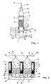
- Figure 1 shows the basic structure of a microreactor assembly 1 in one Sectional plane along the axis of the reaction vessel 2.
- the reaction vessel 2 having a cylindrical interior is at its lower end with a inlet side frit 4 and at its upper end with an outlet side frit. 5 locked. These frits are made of polypropylene.
- the reaction vessel 2 is placed on a base body 11 and relative to this base body 11th sealed by means of a ring seal 11a.
- an inlet channel 6 formed, which has a diameter which is approximately the inner diameter of the reaction space 3 corresponds. At this inlet channel 6 closes down a lower inlet 7 with a corresponding cross-section, in an insert 12th is trained.
- This insert 12 is in a corresponding opening in the lower Screwed portion of the body 11.
- a membrane 9 is inserted, which at her Peripheral edge is sealed by means of an O-ring seal 9a.
- This membrane is made of PTFE material. It is designed in terms of material thickness so that it can oscillate in the direction of the double arrow 19.
- a lateral Inlet channel 8 is formed, as the Reaganzien inlet, through the flow arrow 10 indicated, serves.
- the lateral inlet 8 with a Teflon capillary, denoted by the reference numeral 8a.
- the lower inlet 7 is provided with an inlet channel 12a; this inlet channel 12a is connected to another Teflon capillary 12b. About this Teflon capillary 12b can in the lower inlet 7 below the diaphragm 9 a hydraulic fluid to and be discharged or compressed air and vacuum are created.
- reactor vessel 2 At the top of the reactor vessel 2 is a tapered connecting piece 2a placed, which forms a reactor outlet 23.
- This reactor outlet 23 in turn is connected to a Teflon capillary 23a, which is a closure with hose clamp 23b.
- the main body 11 is made of Teflon and the insert 12 of this microreactor assembly 1 is made of stainless steel, ie of materials that are chemically resistant to Acids, bases and solvents are resistant.
- the reagent is initially the Teflon capillary 8a and the lateral inlet 8 in the vestibule 6 transferred. About this Side inlet 8 can also solvent in the inlet channel 6 and in addition the reaction space 3 are filled. Subsequently, the lateral inlet 8 via a valve arrangement, not shown, or a simple clamping device, closed at the Teflon capillary 8a. In the reaction space 3 is, about over two thirds of its height, filled with polymer resin 17, via the input side and output side frit 4, 5 are retained in the reaction space 3.
- microreactor systems can be constructed, which consists of a number consist of individual microreactors 1.
- the respective ones Reaction spaces 3 of these reactor vessels 2 are in the form of inert polymers coated holes formed in an aluminum plate 15.
- this aluminum plate 15 is placed on top of a PFA top plate 14 with in each case a funnel-shaped recess 14 a, which in a reactor outlet 23 passes, in each of which a schematically indicated outlet valve 13 is integrated.
- Below the aluminum plate 15 is an intermediate plate 22 a, which in turn is covered by a bottom plate 22.
- These sieves 16 can be a continuous, act in the respective layer network arranged with the top plate 14 and the intermediate plate 22a, which are each made of PFA, PTFE or PP, can be welded so that the individual reactor vessel 2 against each other are sealed.
- the intermediate plate 22a and the bottom plate 22 also Made of PFA, PTFE, FEP, PEEK or coated aluminum is a foil inserted, which forms the respective membrane 18, the reaction chambers 3 on the Close feed side.
- this membrane 18 are respective capillary inlets, designated by the reference numeral 20, provided that the lateral Feed 8 of the microreactor assembly of Figure 1 correspond.
- Below the membrane 18 are in the PFA bottom plate 22 inlet channels 21 to see the inlet channels 12a of the microreactor assembly 1 of Figure 1 correspond.
- the membrane can optionally be clamped or with the intermediate plate 22a or with the bottom plate 22 welded.
- the intermediate plate 22a and / or the bottom plate 22 constructed of two plates be, wherein in the parting plane between these two sub-plates, the respective Canals are formed.
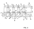
- FIG. 3 A linear drawn, but three-dimensionally expanding microreactor system (schematically for an n x m matrix on the basis of the basic structure Figures 1 and 2 is shown in more detail in Figure 3.
- This arrangement comprises, according to Figure 2, a plate-shaped structure with n x m four reaction spaces 3, four of which are shown in the sketch, in turn through holes are formed in a fluoropolymer or aluminum plate 15.
- In the upper and lower portion of the reaction chambers 3 are each frits 4, 5 used, the one have such porosity that they filled in the reaction spaces 3 resin beads withhold in the reaction space 3.
- an additional valve plate 24 is placed above the top plate 14, which is displaceable in the direction of the double arrow 24a.
- the respective valve openings 13 can be oriented so that they form a passage between the funnel-shaped recesses 14a and the reactor outlets 23, while they interrupt the passage in a shifted position.
- all reactor outlets 23 can be opened or closed.
- On the underside of the aluminum plate 15 is followed by a membrane holding layer 27, to which the membrane 18 is welded, in which the capillary inlets 20 in the area above the membrane 18 are executed.
- the vertical inlet channels comparable to the channels 8 of the arrangement of Figure 1, are arranged, which are in an inlet layer with a common, horizontally extending connecting channel 30 in connection.
- This common connecting channel 30 is designated at its inlet ends with A 1 .
- inlet layer which are denoted by the reference numeral 29 on the one hand and are also designated by the letters B 1 , B 2 , B 3 and B 4 .
- further inlets 29 also lead via the membrane holding layer 27 into the antechambers 6; they are arranged offset to the inlets 8.
- the antechambers 6 below the reaction chambers 3 can be brought into connection with either the inlets 8 or the inlets 29 or completely closed.
- a base plate 32nd provided in the common inlet channels 21, to a movement fluid to apply the membranes 18 are formed.
- the channel system 21 via the inlet end, Denoted at 21a also a gas, for example compressed air / vacuum supplied become.
- Gas has, in contrast to a liquid, the advantage that without external Drive through a 3-way valve, the gas can be performed accordingly.
- FIG. 3 makes clear, the possibility is due to the layered construction given, microreactor systems of a large number of microreactor arrangements, have the volumes of the reaction spaces in quantities of 0.1 to 1.5 ml can build up. While Figure 3 shows a linear array with only 4 microreactor arrays 1, matrix fields are possible which are practically not in size are limited, i. Fields of up to 16 x 24 or more are possible, so that in the In the last case a total of 384 reaction rooms resulted. Such microreactor systems are thus arbitrarily in size and number interpretable, without thereby a significantly increased, constructive structure results.
- a base plate 15 is shown, wherein the respective solid Circles indicate the location of the reaction spaces 3.
- the circles in a broken line show the position of Zulaufkapillar für with the respective antechamber cross-sections.
- 6 In the area of these vestibules 6 each end the lateral inlets 8, which with a respective connection channel 30 are in common, as well as the respective Inlets 29 communicating with a respective communication passage 30a.
- the respective inlets 8 are the one Series associated reaction chambers 3 connected to a common inlet channel 30, while the inlets 29 of each arranged in a column reaction spaces 3 are connected to a common inlet channel 30a.
- each feeds for example, have a diameter of 100 microns can, called.
- the feeds 33 which are assigned to a respective reaction space are each rows or rows with an inlet cross channel 34 (corresponds the inlet channel 30 in Figure 3), whose width is preferably 400th ⁇ m.
- perpendicular to these inlet cross channels 34 are inlet longitudinal channels 35th indicated, which are formed in an underlying layer and with the inlets 29 in Figure 3 are in communication.
- Each of the inlet cross channels 34 has on its inlet side, a valve 38 and on its outlet side a valve 39.
- Valves 38 are three-way valves, while the valves 39 are simple Shut-off valves are. About the three-way valves 38 can between an inlet 36 for Reagents and a feed 37 for reagents or argon are switched. About these valves 38 thus two different reagents the respective Reaction spaces are fed to a line. The supply of argon over the Feed 37 may be required if the reactors are to be emptied. For emptying or rinsing the capillaries, the shut-off valves 39 can be opened and / or closed.
- FIG. 5 shows that with simple means and with a relatively small, design effort reagents synchronous line by line and column several Microreactors are fed to a matrix for a combinatorial synthesis can.
Landscapes
- Chemical & Material Sciences (AREA)
- Chemical Kinetics & Catalysis (AREA)
- Health & Medical Sciences (AREA)
- Organic Chemistry (AREA)
- Analytical Chemistry (AREA)
- General Health & Medical Sciences (AREA)
- Hematology (AREA)
- Clinical Laboratory Science (AREA)
- Physical Or Chemical Processes And Apparatus (AREA)
- Organic Low-Molecular-Weight Compounds And Preparation Thereof (AREA)
Description
- Agitation mittels einer Membran
- das Trägermaterial, z.B. Polymerharz, ist in einem Reaktionsraum oder mehreren Reaktionsräumen (permeable Behälter) eingeschlossen, die jeweils einen Eingang und Ausgang haben, der aus einer Fritte besteht, die für Flüssigkeiten durchlässig ist, das Harz aber zurückhält;
- vor bzw. hinter diesen Fritten Ventile zur Zu- und Ableitung von mehreren Reagenzien und Lösungsmitteln vorhanden sind;
- die Reaktionsräume können aus einem chemisch inerten Material, wie Glas, polymer-beschichtetes Metall, Polypropylen, PEEK, PTFE, FEP oder PFA, etc., bestehen;
- die Reaktionsräume sind von einer wärmeleitenden Ummantelung, z.B. aus Aluminium, umschlossen;
- ein zweites Kanalsystem kann im die Reaktionsräume umgebenden Material vorhanden sein, das als Heiz/Kühlkreislauf dient und durch Wärmeleitung die Reagenzienkanäle und Reaktionskammern temperiert.
- Figur 1
- einen Schnitt durch eine einzelne Mikroreaktoranordnung;
- Figur 2
- einen Schnitt durch zwei nebeneinander angeordnete Mikroreaktoranordnungen, die ein Mikroreaktorsystem bilden, wobei in dieser Figur die Bewegung der Membran verdeutlicht wird;
- Figur 3
- eine Schnittdarstellung eines Mikroreaktorsystems mit vier einzelnen Mikroreaktoranordnungen, wobei hier der Mehrschichtaufbau deutlich wird;
- Figur 4
- eine Ebene einer Schichtstruktur, im Bereich derer Ventile gebildet sind, indem zwei gegeneinander verschiebbare Schichten vorgesehen sind; und
- Figur 5
- eine Ebene einer Schichtstruktur, aus der das Mikroreaktorsystem aufgebaut ist, wobei in dieser Schicht Zuleitungskapillaren gezeigt sind.
- 10 ml DCM - 20 Sekunden Agitation
- 10 ml MeOH - 20 Sekunden Agitation
- 10 ml DCM - 20 Sekunden Agitation
- 20 ml MeOH - 20 Sekunden Agitation
Claims (23)
- Mikroreaktoranordnung zur festphasengestützten Synthese mit mindestens einem Mikroreaktor, der einen Reaktionsraum mit mindestens einem Zulauf und einem Ablauf aufweist, wobei der Reaktionsraum zum Teil mit einem festen Trägermaterial gefüllt ist, wobei im Bereich des Zulaufs und des Ablaufs jeweils eine Fritte den Reaktionsraum abschließt und wobei über mindestens einen Einlaß Lösungsmittel und/oder Reagenzien zuführbar sind, dadurch gekennzeichnet, daß einströmseitig der dem Zulauf (6; 20) zugeordneten Fritte (4; 16) eine flüssigkeits- und gasdichte Membran (18) angeordnet ist,
daß der Einlaß (6; 20) zwischen Membran (18) und Fritte (4; 16) positioniert ist und
daß auf der dem Reaktionsraum (3) abgewandten Seite der Membran (18) eine diese, in Form von oszillierenden Auslenkungen, bewegende Einrichtung vorgesehen ist. - Mikroreaktoranordnung nach Anspruch 1, dadurch gekennzeichnet, daß die Membran (18) in Bezug auf das Volumen des Reaktionsraums (3) derart ausgelegt ist, daß pro auslenkende Bewegung oder Hub der Membran (18) 5 bis 50% des Volumens des Reaktionsraums (3) verdrängbar sind und so die im Reaktionsraum (3) enthaltende Flüssigkeit zur Spülung und/oder Agitation des im Reaktionsraum (3) befindlichen Trägermaterials (17) bewegbar ist.
- Mikroreaktoranordnung nach Anspruch 2, dadurch gekennzeichnet, daß 10 bis 25% des Volumens verdrängbar ist.
- Mikroreaktoranordnung nach Anspruch 1, dadurch gekennzeichnet, daß die Fläche der Membran (18) mindestens der Fläche des Durchmessers des Reaktionsraums (3) entspricht.
- Mikroreaktoranordnung nach Anspruch 1 dadurch gekennzeichnet, daß die Membran (18) aus Fluorpolymeren, insbesondere PTFE, FEP oder PFA gefertigt ist.
- Mikroreaktoranordnung nach Anspruch 5, dadurch gekennzeichnet, daß die Dicke der Membran (18) 100 µm - 500 µm beträgt.
- Mikroreaktoranordnung nach Anspruch 1, dadurch gekennzeichnet, daß im Bereich des Zulaufs (6; 20) und/oder des Ablaufs (23) des Reaktionsraums (3) jeweils ein Ventil (23b) angeordnet ist.
- Mikroreaktoranordnung nach Anspruch 1, dadurch gekennzeichnet, daß die Fritten (4, 5; 16) für Flüssigkeiten durchlässig und für Polymerharze undurchlässig sind.
- Mikroreaktoranordnung nach Anspruch 8, dadurch gekennzeichnet, daß die Fritten (4, 5; 16) aus Polymermaterialien, insbesondere PTFE (Polytetrafluorethylen), PFA (Perfluoroalkoxyalcan-Copolymer), FEP (Tetrafluorethylen-Hexafluorpropylen-Copolymer), PP (Polypropylen) gebildet sind, mit einer offenen Porosität von 2 - 250 µm.
- Mikroreaktoranordnung nach Anspruch 1, dadurch gekennzeichnet, daß die die Membran (18) bewegende Einrichtung wechselweise auf die Membran (18) Gasdruck aufbringt und Vakuum anlegt.
- Mikroreaktoranordnung nach Anspruch 1, dadurch gekennzeichnet, daß zumindest der Reaktionsraum (3) aus einem polymeren Material, insbesondere aus PTFE, PFA, FEP und PP, gebildet ist.
- Mikroreaktoranordnung nach Anspruch 1, dadurch gekennzeichnet, daß der Reaktionsraum (3) zwischen den beiden Fritten (4, 5) ein Volumen im Bereich von 0,1 bis 10 ml, vorzugsweise 0,2 bis 2 ml, aufweist.
- Mikroreaktoranordnung nach Anspruch 1, dadurch gekennzeichnet, daß dem Reaktionsraum (3) eine Heizeinrichtung zugeordnet ist.
- Mikroreaktoranordnung nach Anspruch 13, dadurch gekennzeichnet, daß der Reaktionsraum (3) durch eine wärmeleitende Ummantelung umgeben ist, die mit der Heizeinrichtung beheizbar ist.
- Mikroreaktoranordnung nach Anspruch 14, dadurch gekennzeichnet, daß die wärmeleitende Ummantelung mit einer Kühleinrichtung kühlbar ist.
- Mikroreaktoranordnung nach Anspruch 1, dadurch gekennzeichnet, daß in der Wand des Reaktionsraums (3) das Ende einer Lichtleitform integriert ist.
- Mikroreaktoranordnung nach Anspruch 1, dadurch gekennzeichnet, daß in der Wand des Reaktionsraums (3) ein optisches Fenster integriert ist.
- Mikroreaktorsystem mit einzelnen Mikroreaktoranordnungen (1), wie sie in einem der Ansprüche 1 bis 17 beansprucht sind, die in einer Matrixform aus n Spalten und m Zeilen angeordnet sind, wobei n und m ganzzahlige Werte annehmen.
- Mikroreaktorsystem nach Anspruch 18, dadurch gekennzeichnet, daß die Mikroreaktoranordnungen (1) in eine Plattenstruktur aus einzelnen plattenförmigen Schichten (14, 15, 22, 24, 27, 28) eingearbeitet sind, die senkrecht zu den Achsen der Reaktorräume geschichtet sind.
- Mikroreaktorsystem nach Anspruch 18, dadurch gekennzeichnet, daß auf der Zulaufseite zu den einzelnen Reaktoranordnungen (1) zumindest zeilenweise oder spaltenweise jeweils eine gemeinsame Gaszufuhr und/oder gemeinsame Zufuhr für Lösungsmitteln und/oder Reagenzien vorgesehen ist.
- Mikroreaktorsystem nach Anspruch 18, dadurch gekennzeichnet, daß die jeweiligen Membranen (18) der einzelnen Mikroreaktoranordnungen durch eine zwischen zwei Platten angeordnete Membranfolie gebildet sind.
- Mikroreaktorsystem nach Anspruch 18, dadurch gekennzeichnet, daß die Ventile im Bereich des Zulaufs und/oder des Ablaufs jeweils durch zwei verschiebbare Platten gebildet sind, die jeweils einem Mikroreaktor zugeordnete Ventilöffnungen aufweisen, die in einer Stellung der Platten zueinander einen Durchfluß freigeben und in einer anderen Stellung der beiden Platten zueinander einen Durchfluß sperren.
- Mikroreaktorsystem nach Anspruch 18, dadurch gekennzeichnet, daß die Reaktionsräume (3) der einzelnen Mikroreaktoranordnungen (1) durch Bohrungen in einer plattenförmigen Schicht (15) gebildet sind.
Applications Claiming Priority (5)
| Application Number | Priority Date | Filing Date | Title |
|---|---|---|---|
| DE10039604 | 2000-08-09 | ||
| DE10039604 | 2000-08-09 | ||
| DE10057827 | 2000-11-21 | ||
| DE10057827A DE10057827A1 (de) | 2000-08-09 | 2000-11-21 | Mikroreaktoranordnung zur festphasengestützten Synthese sowie Mikroreaktorsystem mit einzelnen Mikroreaktoranordnungen |
| PCT/EP2001/007376 WO2002011880A2 (de) | 2000-08-09 | 2001-06-28 | Mikroreaktoranordnung zur festphasengestützten synthese sowie mikroreaktorsystem mit einzelnen mikroreaktoranordnungen |
Publications (2)
| Publication Number | Publication Date |
|---|---|
| EP1309397A2 EP1309397A2 (de) | 2003-05-14 |
| EP1309397B1 true EP1309397B1 (de) | 2005-02-02 |
Family
ID=26006690
Family Applications (1)
| Application Number | Title | Priority Date | Filing Date |
|---|---|---|---|
| EP01969323A Expired - Lifetime EP1309397B1 (de) | 2000-08-09 | 2001-06-28 | Mikroreaktoranordnung zur festphasengestützten synthese sowie mikroreaktorsystem mit einzelnen mikroreaktoranordnungen |
Country Status (4)
| Country | Link |
|---|---|
| EP (1) | EP1309397B1 (de) |
| AT (1) | ATE288320T1 (de) |
| AU (1) | AU2001289614A1 (de) |
| WO (1) | WO2002011880A2 (de) |
Families Citing this family (10)
| Publication number | Priority date | Publication date | Assignee | Title |
|---|---|---|---|---|
| US7485454B1 (en) | 2000-03-10 | 2009-02-03 | Bioprocessors Corp. | Microreactor |
| DE10046175A1 (de) * | 2000-09-19 | 2002-03-28 | Augustinus Bader | Verfahren und Vorrichtung zum Züchten und/oder Behandeln von Zellen |
| EP1509315A2 (de) * | 2002-06-05 | 2005-03-02 | Bioprocessors Corporation | Materialien und reaktorsysteme mit feuchtigkeits- und gasregelung |
| DE10341500A1 (de) * | 2003-09-05 | 2005-03-31 | Ehrfeld Mikrotechnik Ag | Mikrophotoreaktor zur Durchführung photochemischer Reaktionen |
| DE102005003966A1 (de) * | 2005-01-27 | 2006-08-10 | Ehrfeld Mikrotechnik Bts Gmbh | Vorrichtung zur kontinuierlichen Durchführung photochemischer Prozesse mit geringen optischen Schichtdicken, enger Verweilzeitverteilung und hohen Durchsätzen |
| JP2007038047A (ja) * | 2005-07-29 | 2007-02-15 | Sumitomo Electric Ind Ltd | マイクロリアクタ |
| US7998418B1 (en) | 2006-06-01 | 2011-08-16 | Nanotek, Llc | Evaporator and concentrator in reactor and loading system |
| US7641860B2 (en) | 2006-06-01 | 2010-01-05 | Nanotek, Llc | Modular and reconfigurable multi-stage microreactor cartridge apparatus |
| US7854902B2 (en) | 2006-08-23 | 2010-12-21 | Nanotek, Llc | Modular and reconfigurable multi-stage high temperature microreactor cartridge apparatus and system for using same |
| US7797988B2 (en) | 2007-03-23 | 2010-09-21 | Advion Biosystems, Inc. | Liquid chromatography-mass spectrometry |
Family Cites Families (4)
| Publication number | Priority date | Publication date | Assignee | Title |
|---|---|---|---|---|
| US3712591A (en) * | 1971-11-24 | 1973-01-23 | Nasa | Zero gravity liquid mixer |
| FR2673631B1 (fr) * | 1991-03-06 | 1993-05-21 | Rhone Poulenc Chimie | Procede et appareil de synthese en phase heterogene de macromolecules telles que des peptides, des polynucleotides ou des oligosaccharides. |
| US5736100A (en) * | 1994-09-20 | 1998-04-07 | Hitachi, Ltd. | Chemical analyzer non-invasive stirrer |
| DE19611270A1 (de) * | 1996-03-22 | 1997-09-25 | Gesim Ges Fuer Silizium Mikros | Mikromischer zur Handhabung kleinster Flüssigkeitsmengen |
-
2001
- 2001-06-28 EP EP01969323A patent/EP1309397B1/de not_active Expired - Lifetime
- 2001-06-28 AU AU2001289614A patent/AU2001289614A1/en not_active Abandoned
- 2001-06-28 AT AT01969323T patent/ATE288320T1/de not_active IP Right Cessation
- 2001-06-28 WO PCT/EP2001/007376 patent/WO2002011880A2/de not_active Ceased
Also Published As
| Publication number | Publication date |
|---|---|
| EP1309397A2 (de) | 2003-05-14 |
| WO2002011880A2 (de) | 2002-02-14 |
| ATE288320T1 (de) | 2005-02-15 |
| WO2002011880A3 (de) | 2002-04-25 |
| AU2001289614A1 (en) | 2002-02-18 |
Similar Documents
| Publication | Publication Date | Title |
|---|---|---|
| DE60300980T2 (de) | Lochmikromischer | |
| DE60208235T2 (de) | Mikrofluidische vorrichtungen mit verteilungseinlässen | |
| DE19935433A1 (de) | Mikrofluidischer Reaktionsträger | |
| DE60108482T2 (de) | Prozessoptimierungsreaktor mit parallelem durchfluss | |
| DE19947495C2 (de) | Mikrofluidischer Mikrochip | |
| DE69534086T2 (de) | Methoden zur Benutzung eines modularen Reaktionssystems im Nanomassstab | |
| DE69303898T2 (de) | Fluessigkeitsbehandlung in mikrofabrizierten analytischen vorrichtungen | |
| DE69706313T2 (de) | Verfahren und vorrichtung, reagenzien zu transferieren und zu kombinieren | |
| DE19950809A1 (de) | Verfahren und Vorrichtung für eine Flüssigkeitsübertragung | |
| WO1995030476A1 (de) | Verfahren und vorrichtung zur durchführung chemischer reaktionen mittels mikrostruktur-mischung | |
| DE69701534T2 (de) | Laborreaktor zur automatisierten Peptidesynthese | |
| DE19830607A1 (de) | Verfahren zum Nachweis eines Produktes im Abstrom eines katalytischen Materials einer Vielzahl von katalytischen Materialien | |
| DE10138970A1 (de) | Rohrreaktor auf Basis eines Schichtstoffes | |
| EP1309397A2 (de) | Mikroreaktoranordnung zur festphasengestützten synthese sowie mikroreaktorsystem mit einzelnen mikroreaktoranordnungen | |
| DE19602464B4 (de) | Vorrichtung zur multiplen, gleichzeitigen und parallelen Synthese chemischer Verbindungen und zur diskreten Weiterbehandlung von Aliquoten | |
| DE10148210B4 (de) | Flusskammer | |
| EP1750155B1 (de) | Verfahren zur Herstellung einer Probenkammer | |
| DE19917433C2 (de) | Mikroreaktorsystem zum Erzeugen und Testen von Substanzen und Wirkstoffen | |
| DE102008002509A1 (de) | Stopped-Flow-Chip | |
| DE10304855A1 (de) | Vorrichtung und Verfahren zum simultanen Agitieren von Reaktionsmischungen | |
| DE102005000835B3 (de) | Verfahren und Vorrichtung zur Dosierung kleiner Flüssigkeitsmengen | |
| DE10132252B4 (de) | Vorrichtung zur Durchführung von katalytischen Tests | |
| EP1222028B1 (de) | Trägerplatte für eine geordnete aufnahme von probenpartikeln | |
| DE10057827A1 (de) | Mikroreaktoranordnung zur festphasengestützten Synthese sowie Mikroreaktorsystem mit einzelnen Mikroreaktoranordnungen | |
| DE102021115994B3 (de) | Vorrichtung und Verfahren für das Mischen von zwei Flüssigkeiten oder Pasten |
Legal Events
| Date | Code | Title | Description |
|---|---|---|---|
| PUAI | Public reference made under article 153(3) epc to a published international application that has entered the european phase |
Free format text: ORIGINAL CODE: 0009012 |
|
| 17P | Request for examination filed |
Effective date: 20030205 |
|
| AK | Designated contracting states |
Designated state(s): AT BE CH CY DE DK ES FI FR GB GR IE IT LI LU MC NL PT SE TR |
|
| RAP1 | Party data changed (applicant data changed or rights of an application transferred) |
Owner name: FRAUNHOFER-GESELLSCHAFT ZUR FOERDERUNG DERANGEWAND |
|
| GRAP | Despatch of communication of intention to grant a patent |
Free format text: ORIGINAL CODE: EPIDOSNIGR1 |
|
| GRAS | Grant fee paid |
Free format text: ORIGINAL CODE: EPIDOSNIGR3 |
|
| GRAA | (expected) grant |
Free format text: ORIGINAL CODE: 0009210 |
|
| AK | Designated contracting states |
Kind code of ref document: B1 Designated state(s): AT BE CH CY DE DK ES FI FR GB GR IE IT LI LU MC NL PT SE TR |
|
| PG25 | Lapsed in a contracting state [announced via postgrant information from national office to epo] |
Ref country code: IT Free format text: LAPSE BECAUSE OF FAILURE TO SUBMIT A TRANSLATION OF THE DESCRIPTION OR TO PAY THE FEE WITHIN THE PRESCRIBED TIME-LIMIT;WARNING: LAPSES OF ITALIAN PATENTS WITH EFFECTIVE DATE BEFORE 2007 MAY HAVE OCCURRED AT ANY TIME BEFORE 2007. THE CORRECT EFFECTIVE DATE MAY BE DIFFERENT FROM THE ONE RECORDED. Effective date: 20050202 Ref country code: TR Free format text: LAPSE BECAUSE OF FAILURE TO SUBMIT A TRANSLATION OF THE DESCRIPTION OR TO PAY THE FEE WITHIN THE PRESCRIBED TIME-LIMIT Effective date: 20050202 Ref country code: FR Free format text: LAPSE BECAUSE OF NON-PAYMENT OF DUE FEES Effective date: 20050202 Ref country code: FI Free format text: LAPSE BECAUSE OF FAILURE TO SUBMIT A TRANSLATION OF THE DESCRIPTION OR TO PAY THE FEE WITHIN THE PRESCRIBED TIME-LIMIT Effective date: 20050202 Ref country code: IE Free format text: LAPSE BECAUSE OF FAILURE TO SUBMIT A TRANSLATION OF THE DESCRIPTION OR TO PAY THE FEE WITHIN THE PRESCRIBED TIME-LIMIT Effective date: 20050202 Ref country code: GB Free format text: LAPSE BECAUSE OF FAILURE TO SUBMIT A TRANSLATION OF THE DESCRIPTION OR TO PAY THE FEE WITHIN THE PRESCRIBED TIME-LIMIT Effective date: 20050202 Ref country code: NL Free format text: LAPSE BECAUSE OF FAILURE TO SUBMIT A TRANSLATION OF THE DESCRIPTION OR TO PAY THE FEE WITHIN THE PRESCRIBED TIME-LIMIT Effective date: 20050202 |
|
| REG | Reference to a national code |
Ref country code: GB Ref legal event code: FG4D Free format text: NOT ENGLISH |
|
| REG | Reference to a national code |
Ref country code: CH Ref legal event code: EP |
|
| REG | Reference to a national code |
Ref country code: IE Ref legal event code: FG4D Free format text: GERMAN |
|
| REF | Corresponds to: |
Ref document number: 50105256 Country of ref document: DE Date of ref document: 20050310 Kind code of ref document: P |
|
| PG25 | Lapsed in a contracting state [announced via postgrant information from national office to epo] |
Ref country code: GR Free format text: LAPSE BECAUSE OF FAILURE TO SUBMIT A TRANSLATION OF THE DESCRIPTION OR TO PAY THE FEE WITHIN THE PRESCRIBED TIME-LIMIT Effective date: 20050502 Ref country code: DK Free format text: LAPSE BECAUSE OF FAILURE TO SUBMIT A TRANSLATION OF THE DESCRIPTION OR TO PAY THE FEE WITHIN THE PRESCRIBED TIME-LIMIT Effective date: 20050502 Ref country code: SE Free format text: LAPSE BECAUSE OF FAILURE TO SUBMIT A TRANSLATION OF THE DESCRIPTION OR TO PAY THE FEE WITHIN THE PRESCRIBED TIME-LIMIT Effective date: 20050502 |
|
| PG25 | Lapsed in a contracting state [announced via postgrant information from national office to epo] |
Ref country code: ES Free format text: LAPSE BECAUSE OF FAILURE TO SUBMIT A TRANSLATION OF THE DESCRIPTION OR TO PAY THE FEE WITHIN THE PRESCRIBED TIME-LIMIT Effective date: 20050513 |
|
| PG25 | Lapsed in a contracting state [announced via postgrant information from national office to epo] |
Ref country code: LU Free format text: LAPSE BECAUSE OF NON-PAYMENT OF DUE FEES Effective date: 20050628 Ref country code: AT Free format text: LAPSE BECAUSE OF NON-PAYMENT OF DUE FEES Effective date: 20050628 Ref country code: CY Free format text: LAPSE BECAUSE OF FAILURE TO SUBMIT A TRANSLATION OF THE DESCRIPTION OR TO PAY THE FEE WITHIN THE PRESCRIBED TIME-LIMIT Effective date: 20050628 |
|
| PG25 | Lapsed in a contracting state [announced via postgrant information from national office to epo] |
Ref country code: CH Free format text: LAPSE BECAUSE OF NON-PAYMENT OF DUE FEES Effective date: 20050630 Ref country code: LI Free format text: LAPSE BECAUSE OF NON-PAYMENT OF DUE FEES Effective date: 20050630 Ref country code: MC Free format text: LAPSE BECAUSE OF NON-PAYMENT OF DUE FEES Effective date: 20050630 Ref country code: BE Free format text: LAPSE BECAUSE OF NON-PAYMENT OF DUE FEES Effective date: 20050630 |
|
| NLV1 | Nl: lapsed or annulled due to failure to fulfill the requirements of art. 29p and 29m of the patents act | ||
| GBV | Gb: ep patent (uk) treated as always having been void in accordance with gb section 77(7)/1977 [no translation filed] |
Effective date: 20050202 |
|
| REG | Reference to a national code |
Ref country code: IE Ref legal event code: FD4D |
|
| PLBE | No opposition filed within time limit |
Free format text: ORIGINAL CODE: 0009261 |
|
| STAA | Information on the status of an ep patent application or granted ep patent |
Free format text: STATUS: NO OPPOSITION FILED WITHIN TIME LIMIT |
|
| 26N | No opposition filed |
Effective date: 20051103 |
|
| REG | Reference to a national code |
Ref country code: CH Ref legal event code: PL |
|
| EN | Fr: translation not filed | ||
| BERE | Be: lapsed |
Owner name: FRAUNHOFER-GESELLSCHAFT ZUR FORDERUNG DER ANGEWAND Effective date: 20050630 |
|
| PG25 | Lapsed in a contracting state [announced via postgrant information from national office to epo] |
Ref country code: PT Free format text: LAPSE BECAUSE OF NON-PAYMENT OF DUE FEES Effective date: 20050702 |
|
| PGFP | Annual fee paid to national office [announced via postgrant information from national office to epo] |
Ref country code: DE Payment date: 20150623 Year of fee payment: 15 |
|
| REG | Reference to a national code |
Ref country code: DE Ref legal event code: R119 Ref document number: 50105256 Country of ref document: DE |
|
| PG25 | Lapsed in a contracting state [announced via postgrant information from national office to epo] |
Ref country code: DE Free format text: LAPSE BECAUSE OF NON-PAYMENT OF DUE FEES Effective date: 20170103 |