EP1308664B1 - Schnellkupplung für die lösbare Verbindung zweier Rohrleitungen - Google Patents
Schnellkupplung für die lösbare Verbindung zweier Rohrleitungen Download PDFInfo
- Publication number
- EP1308664B1 EP1308664B1 EP02356222A EP02356222A EP1308664B1 EP 1308664 B1 EP1308664 B1 EP 1308664B1 EP 02356222 A EP02356222 A EP 02356222A EP 02356222 A EP02356222 A EP 02356222A EP 1308664 B1 EP1308664 B1 EP 1308664B1
- Authority
- EP
- European Patent Office
- Prior art keywords
- ramp
- connector
- towards
- seat
- protruding part
- Prior art date
- Legal status (The legal status is an assumption and is not a legal conclusion. Google has not performed a legal analysis and makes no representation as to the accuracy of the status listed.)
- Expired - Lifetime
Links
Images


Classifications
-
- F—MECHANICAL ENGINEERING; LIGHTING; HEATING; WEAPONS; BLASTING
- F16—ENGINEERING ELEMENTS AND UNITS; GENERAL MEASURES FOR PRODUCING AND MAINTAINING EFFECTIVE FUNCTIONING OF MACHINES OR INSTALLATIONS; THERMAL INSULATION IN GENERAL
- F16L—PIPES; JOINTS OR FITTINGS FOR PIPES; SUPPORTS FOR PIPES, CABLES OR PROTECTIVE TUBING; MEANS FOR THERMAL INSULATION IN GENERAL
- F16L37/00—Couplings of the quick-acting type
- F16L37/08—Couplings of the quick-acting type in which the connection between abutting or axially overlapping ends is maintained by locking members
- F16L37/10—Couplings of the quick-acting type in which the connection between abutting or axially overlapping ends is maintained by locking members using a rotary external sleeve or ring on one part
- F16L37/113—Couplings of the quick-acting type in which the connection between abutting or axially overlapping ends is maintained by locking members using a rotary external sleeve or ring on one part the male part having lugs on its periphery penetrating into the corresponding slots provided in the female part
-
- F—MECHANICAL ENGINEERING; LIGHTING; HEATING; WEAPONS; BLASTING
- F16—ENGINEERING ELEMENTS AND UNITS; GENERAL MEASURES FOR PRODUCING AND MAINTAINING EFFECTIVE FUNCTIONING OF MACHINES OR INSTALLATIONS; THERMAL INSULATION IN GENERAL
- F16L—PIPES; JOINTS OR FITTINGS FOR PIPES; SUPPORTS FOR PIPES, CABLES OR PROTECTIVE TUBING; MEANS FOR THERMAL INSULATION IN GENERAL
- F16L37/00—Couplings of the quick-acting type
- F16L37/08—Couplings of the quick-acting type in which the connection between abutting or axially overlapping ends is maintained by locking members
- F16L37/084—Couplings of the quick-acting type in which the connection between abutting or axially overlapping ends is maintained by locking members combined with automatic locking
-
- F—MECHANICAL ENGINEERING; LIGHTING; HEATING; WEAPONS; BLASTING
- F16—ENGINEERING ELEMENTS AND UNITS; GENERAL MEASURES FOR PRODUCING AND MAINTAINING EFFECTIVE FUNCTIONING OF MACHINES OR INSTALLATIONS; THERMAL INSULATION IN GENERAL
- F16L—PIPES; JOINTS OR FITTINGS FOR PIPES; SUPPORTS FOR PIPES, CABLES OR PROTECTIVE TUBING; MEANS FOR THERMAL INSULATION IN GENERAL
- F16L37/00—Couplings of the quick-acting type
- F16L37/28—Couplings of the quick-acting type with fluid cut-off means
- F16L37/38—Couplings of the quick-acting type with fluid cut-off means with fluid cut-off means in only one of two pipe-end fittings
- F16L37/40—Couplings of the quick-acting type with fluid cut-off means with fluid cut-off means in only one of two pipe-end fittings with a lift valve being opened automatically when the coupling is applied
- F16L37/42—Couplings of the quick-acting type with fluid cut-off means with fluid cut-off means in only one of two pipe-end fittings with a lift valve being opened automatically when the coupling is applied the valve having an axial bore communicating with lateral apertures
Definitions
- the invention relates to a quick coupling which comprises elements that fit into each other for the removable connection of two pipes traversed by a fluid under pressure.
- fittings comprising balls and a locking sleeve, the balls being controlled by the position of the socket around one of the elements of the fitting.
- These fittings require sufficient free space around the fittings for the operation of the socket, such a volume not being always available.
- the locking movement and Unlocking the coupling, with stop in positon of decompression can be carried out essentially according to a axial direction, without requiring rotation by the user.
- the rotation corresponding to locking is achieved by the rotational movement automatic ring relative to the element on which it is mounted, while the decompression is obtained by locking of the protruding element on the second seat.
- the concept of "fixed in translation » means that the ring is immobilized axially between two stops.
- some game remains eligible, which corresponds to a possibility of axial movements of low amplitude for the ring.
- the invention can be implemented with different embodiments.
- the ramp is formed on the inner radial surface of a mounted ring free in rotation and fixed in translation inside the female element of the connection, while the part in projection is fixed relative to the male element.
- the ramp is formed on the inner radial surface of a body of the female element of the connection, while the part in protrusion is secured to a ring mounted free in rotation and fixed in translation around the male element.
- the ramp is formed on the outer radial surface of a mounted ring free in rotation and fixed in translation around the male part of the coupling, while the projecting part is fixed with respect to the female element and extends radially inwardly thereof.
- the ramp is formed on the outer radial surface of the male element of the connection, while the projecting portion is integral with a ring mounted freely in rotation and fixed in translation to inside the female element, the protruding part extending radially inwardly of this element.
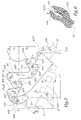
- connection shown in FIGS. 1 to 5 comprises a male element A and a female element B both provided with a generally cylindrical shape with circular section.
- the rear part of the male element A is fluidly connected to a first pipe, or upstream pipe, C 1
- the rear part of the female element B is connected to a second pipe, or downstream pipe, C 2 .
- X-X the main axis of the connection formed by elements A and B, that is to say the main axis of the elements A and B in the configurations of FIGS. 1 to 4, axis according to the direction from which these elements can be moved one in the other.
- the element A comprises a body 11 inside which is disposed a valve 12 loaded elastically by a spring 13 exerting a force F 1 tending to press a head 14 of the valve 12 equipped with an O-ring 15 against a seat 16 formed by the body 11.
- a second O-ring 17 is provided in an annular groove 18 formed inside the body 11.
- the body 11 On its outer radial surface 19, the body 11 is provided with two lugs 20 and 21 which are diametrically opposite one another. relative to the other and extending in a direction YY 'generally perpendicular to the axis X-X'.
- the lugs 20 and 21 are integral with the body 11.
- the element B comprises a body 31 forming a pusher 32 designed to penetrate the internal volume 22 of the body 11 and push the valve 12 against the force F 1 .
- a ring 33 is mounted in a housing 34 provided in the inner radial surface 35 of the body 31, the ring 33 being free to rotate relative to the body 31 about the axis XX 'and fixed in translation relative to this body along this axis, due to its bearing against the opposite edges 34 a and 34 b of the housing 34.
- a bore 36 connects the housing 34 to the outside of the element B, through the body 31.
- the ring 33 On its internal radial surface 37, the ring 33 is provided with two ramps 40 and 41 formed recess in the surface 37.
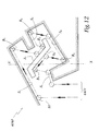
- the geometry of the ramp 40 is developed at the Figure 5 where the trace of the pin 20 is shown in several positions, in phantom.
- the ramp 40 comprises an inlet section 401 convergent towards a 402 passage extending overall in a direction parallel to the axis X-X '.
- a part curve 403 is also provided, this part is extending by a recess 404 whose radius of curvature is such that it can receive and serve as a stop the spur 20.
- the lug 20 progresses in the section 401 in the direction of the passage 402, as represented by the arrows F 2 , F ' 2 and F'' 2 which correspond to different possible angular orientations of the lugs 20 relative to the ring 33 at the start of the fitting.
- the progression of the ergot 20 corresponds to a relative movement of the lug relative to the ring 33, because the ring rotates around the axis X-X '.
- the lug 20 then reaches the passage 402 and then follows the curved portion 403 as represented by the arrow F 3 , so that it reaches the stop in the recess 404. It is then in a maximum fitting configuration of the lug. male element A in the female element B.
- the force F 1 tends to push the pusher 32 towards the outside of the volume 22, which induces a relative movement of the male and female elements in an opening direction.
- the lug 20 When the lug 20 bears against the surface 405 and taking into account the orientation of this surface with respect to the X-X 'axis, the lug 20 slides against this surface until it is immobilized in a second recess 406 whose geometry is such that it can serve as a locking seat of the lug 20 in the ramp 40.
- the arrow F 5 represents the progression of the lug 20 along the surface 405.
- the ramp 40 comprises a second passage 409 generally parallel to the axis X-X ', this passage being prolonged by a curved portion 410 which opens out to a recess 411 forming a second locking seat of the lug 20. Note 412 the outer surface of the ramp 40 at the curved portion 410, this surface for guiding the pin 20 towards the recess 411, as shown by the arrow F 9.
- the recesses 404 and 408 are generally aligned in a direction D perpendicular to the axis X-X 'in FIG. 5, so that the distance d 1 also corresponds to the distance, taken parallel to the axis X-X' , between the center of the lug 20 respectively in place in the recesses 406 and 408. This alignment of the recesses 404 and 408 is however not mandatory.
- d 2 the distance, taken parallel to the axis X-X 'between the center of the lug 20 respectively in place in the recesses 406 and 411.
- the value of the distance d 2 is chosen such that, when the lug 20 is in place in the recess 411, the connection is in the configuration of Figure 3, wherein the pusher 32, although still engaged in the volume 22 does not overlap a notch 23 provided on the body 11, which allows a flow of the fluid present in the downstream pipe C 2 in the direction of a volume V formed around the pusher 32 and inside the body 31.
- a notch 38 provided on an edge of the ring 33 allows a discharge of the fluid to the outside of the connection, through the bore 36, this flow being represented by the arrows E in FIG.
- the lug then progresses along this surface, as represented by the arrow F 11 and reached a third recess 414, from which the lug 20 can be moved, as represented by the arrow F 12 , towards a surface 415 inclined with respect to the axis XX 'in the same direction as the surfaces 405 and 412
- the pin 20 can then slide along this surface towards the outlet opening 416 of the ramp 40, as represented by the arrow F 13 .
- the opening 416 corresponds, in fact, to the opening of the ramp 41. Indeed, the angle ⁇ between the openings 401 and 416 is equal to about 180 °, each of ramps 40 and 41 extending substantially over half a circumference inner ring 33.
- the ergot 20 can be easily removed from the ramp 40.
- the surface 415 defines, with a surface 415 'inclined in the opposite direction relative to the axis X-X', a spout 415 '' generally axially aligned with the recess 414. This spout opposes an axial introduction of the lug 20 towards the recess 414 and deflects it towards the section 401 and the passage 402, which is represented by the arrow F ' 2 in FIG.
- the ring 33 is mechanically protected against shocks and against pollution by the body 31.
- the lugs 20 and 21 being integral with the body 11, the male end A is very robust and can be mounted to the end of a hose.
- an elastic blade 418 fixed by a rivet 419 or any other means in the bottom 420 of the ramp 40, this blade 418 tending, under the effect of its own elasticity, to take off its end free 418 relative to the bottom 420, as shown by the arrow F14.
- the different surfaces 403, 407 and 413 which lead at the recesses 404, 408 and 414 and are inclined by relative to the X-X 'axis, are respectively opposite surfaces 405 and 412, which lead to seats 406 and 411 and are inclined in opposite directions with respect to this axis.
- the guiding surfaces respectively to the recesses or to the seats are axially aligned with seats or recesses in which the lugs may change direction or rest.
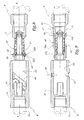
- the second embodiment differs from the previous embodiment in that the ramps, only one of which is visible with the reference 40, are formed on the internal radial surface 35 of the body 31 of the female element, whereas the lugs 20 and 21 are diametrically opposed. are formed on a ring 24 mounted in a groove 25 formed on an outer radial surface 19 of the body 11.
- the locking of the male and female elements A and B is obtained by the rotation of the ring 24, about the longitudinal axis XX ' of the fitting, the ring being immobilized in translation parallel to this axis by its bearing against the opposite edges 25 a and 25 b of the groove 25.
- two lugs 20 and 21 are immobilized on the body 31 of the female element B and protrude with respect to the surface 35 in the direction of the axis X-X '.
- a ring 26 is provided in a groove 27 formed on the outer radial surface 19 of the body 11, this ring defining ramps 40 and 41 on its outer radial surface 26 a .
- the ring 26 is mounted to rotate freely in the groove 27 and is immobilized in translation, parallel to the axis X-X ', by its support on the opposite edges 27a and 27b of groove 27.
- the ramps 40 and 41 are machined directly on the outer radial surface 19 of the body 11 of the male element, while a ring 39 carrying two lugs 20 and 21 is housed, with possibility of rotation, in a groove 42 formed on the inner radial surface 35 of the body 31 of the female element B.
- the ring 39 can rotate freely about the axis X-X ', while it is immobilized in parallel translation to this axis, because it bears against the opposite edges 42 a and 42 b of the groove 42.
- the second, third and fourth modes of realization work in a similar way to that described with reference to the first embodiment.
- a ramp 1040 is formed and delimited by surfaces S 1 to S 5 , each terminating in a stop B 1 to B 5 .
- the stops B 2 and B 4 are seats equivalent to the seats 406 and 411 of the first embodiment, while the stops B 1 , B 3 and B 5 correspond to recesses in which the projecting parts can be reoriented by sliding on a surface S 1 , S 3 or S 5 to go towards another surface S 2 , S 4 or towards the exit of the ramp 1040.
- a difference compared to the first mode of realization also lies in the fact that the ramp 1040 has a common area 1401 input and output of an element protruding, of the type of the pawn 20.
- FIG. 12 represents a sixth embodiment in which six surfaces S 1 to S 6 inclined with respect to a longitudinal axis XX 'of the coupling define five stops B 1 to B 5 , two of which, the stops B 2 and B 4 constitute seats retaining a projecting portion, three other abutments B 1 , B 3 and B 5 constituting zones of change of direction of the projecting portion within the ramp 4040 thus formed.
- the inlet and the outlet of the ramp 4040 are constituted by a common zone 4401.
- the surfaces S 1 to S 6 are located facing the abutments B 1 to B 5 while being axially offset relative thereto. The same observations are valid for the surfaces and indentations identified in the first embodiment.
Landscapes
- Engineering & Computer Science (AREA)
- General Engineering & Computer Science (AREA)
- Mechanical Engineering (AREA)
- Quick-Acting Or Multi-Walled Pipe Joints (AREA)
Claims (10)
- Schnellkupplung für die lösbare Verbindung zweier Rohrleitungen, wobei die Kupplung ein erstes und ein zweites Element (A, B) umfasst, die entsprechend einer Hauptachse (X-X') der Kupplung ineinandergreifen können, wobei das erste Element mindestens eine Rampe zur Aufnahme eines radialen, hervorspringenden Teils des zweiten Elements zur Verriegelung der Elemente in durchleitender Anordnung der Kupplung umfasst, wobei die Rampe (40, 41; 1040; 4040) oder der hervorspringende Teil (20, 21) in einem Ring (33; 25; 26; 39) ausgebildet ist oder Bestandteil desselben ist, der an einem der Elemente (A, B) in Drehfreiheit und feststehend in Längsrichtung entsprechend der Achse (X-X') montiert ist und die Rampe mindestens einen Verriegelungssitz (406; B2) des hervorspringenden Teils in durchleitender Anordnung der Kupplung bildet,
dadurch gekennzeichnet, dass die Rampe (40, 41; 1040; 4040) einen zweiten, axial in Bezug auf dem ersten Sitz (406; B2) in Öffnungsrichtung der Kupplung versetzt angeordneten Sitz (411; B4) für die Verriegelung des hervorspringenden Teils (20, 21) in einer Anordnung der Druckverminderung (E) der stromabwärts gelegenen Leitung (C2) der Kupplung bildet. - Kupplung nach Anspruch 1, dadurch gekennzeichnet, dass die Rampe (40, 41; 1040; 4040) durch Flächen (403, 405, 407, 412, 413, 415, S1-S6) begrenzt ist, die in Bezug auf die Achse (X-X') geneigt sind und axial gegenüberliegend zu Verstärkungen (404, 406, 408, 411; B1-B5) angeordnet sind und Sitze oder Anschläge für die Aufnahme und/oder die Nachführung des hervorspringenden Teils (20) bilden.
- Kupplung nach einem der vorhergehenden Ansprüche, dadurch gekennzeichnet, dass die Rampe (40, 41) mit einer Eingangs(F2)-Öffnung (401) des hervorspringenden Teils (20, 21) und einer Ausgangs(F13)-Öffnung (416) des genannten Teils versehen ist, wobei die Öffnungen in Bezug auf die Achse in zwei bestimmte radiale Richtungen orientiert (α) sind.
- Kupplung nach einem der Ansprüche 1 oder 2, dadurch gekennzeichnet, dass der Eingang und der Ausgang der Rampe (1040; 4040) aus einer einzigen Durchgangszone (1401; 4401) für den hervorspringenden Teil (20, 21) gebildet sind.
- Kupplung nach einem der vorhergehenden Ansprüche, dadurch gekennzeichnet, dass die Rampe eine Eingangszone (401) umfasst, die in Richtung eines ersten, in Richtung einer Anschlagszone (404) orientierten Durchgangs (402) konvergiert, entsprechend einer ineinandergreifenden (d1) Anordnung der Elemente (A, B), wobei die Anschlagszone gegenüberliegend zu einer Fläche (405) zur Führung des hervorspringenden Teils (20, 21) in Richtung des Verriegelungssitzes (406) in der durchleitenden Anordnung angeordnet ist.
- Kupplung nach einem der vorhergehenden Ansprüche, dadurch gekennzeichnet, dass die Rampe (40, 41) mit einer Rückdrehsicherungsvorrichtung (418) ausgerüstet ist, die mit dem Fortschreiten des hervorspringenden Teils (20, 21) von einer Eingangszone (401) zu einer Ausgangszone (416) der Rampe in einer einzigen Richtung (F2) kompatibel ist.
- Kupplung nach einem der vorhergehenden Ansprüche, dadurch gekennzeichnet, dass die Rampe (40, 41) auf der radialen Innenfläche (37) eines Ringes (33) ausgebildet ist, der drehfrei und in translatorischer Richtung feststehend im Inneren des Aufnahmeelements (B) der Kupplung montiert ist, und dass der hervorspringende Teil (20, 21) in Bezug auf das Einsteckelement (A) fest ist.
- Kupplung nach einem der Ansprüche 1 bis 6, dadurch gekennzeichnet, dass die Rampe (40, 41) auf der radialen Innenfläche (35) eines Körpers (31) des Aufnahmeelements (B) der Kupplung ausgebildet ist und dass der hervorspringende Teil (20, 21) Bestandteil eines Ringes (24) ist, der drehfrei und in translatorischer Richtung um das Einsteckelement (A) herum montiert ist.
- Kupplung nach einem der Ansprüche 1 bis 6, dadurch gekennzeichnet, dass die Rampe (40, 41) auf der radialen Außenfläche (26a) eines Rings (26) ausgebildet ist, der drehfrei und fest in translatorischer Richtung um das Einsteckelement (A) der Kupplung montiert ist, und dass der hervorspringende Teil (20, 21) fest in Bezug auf das Aufnahmeelement (B) ist und sich radial in dessen Inneres erstreckt.
- Kupplung nach einem der Ansprüche 1 bis 6, dadurch gekennzeichnet, dass die Rampe (40, 41) auf der radialen Außenfläche (19) des Einsteckelements (A) der Kupplung ausgebildet ist, und dass der hervorspringende Teil (20, 21) Bestandteil eines Ringes (39) ist, der drehfrei und in translatorischer Richtung fest im Inneren des Aufnahmeelements (B) montiert ist, wobei der hervorspringende Teil sich radial in das Innere dieses Elements erstreckt.
Applications Claiming Priority (2)
| Application Number | Priority Date | Filing Date | Title |
|---|---|---|---|
| FR0114346A FR2831940B1 (fr) | 2001-11-06 | 2001-11-06 | Raccord rapide pour la jonction amovible de deux canalisations |
| FR0114346 | 2001-11-06 |
Publications (3)
| Publication Number | Publication Date |
|---|---|
| EP1308664A2 EP1308664A2 (de) | 2003-05-07 |
| EP1308664A3 EP1308664A3 (de) | 2003-10-22 |
| EP1308664B1 true EP1308664B1 (de) | 2005-05-18 |
Family
ID=8869116
Family Applications (2)
| Application Number | Title | Priority Date | Filing Date |
|---|---|---|---|
| EP02356221A Expired - Lifetime EP1308663B1 (de) | 2001-11-06 | 2002-11-05 | Schnellkupplung für die lösbare Verbindung zweier Rohrleitungen |
| EP02356222A Expired - Lifetime EP1308664B1 (de) | 2001-11-06 | 2002-11-05 | Schnellkupplung für die lösbare Verbindung zweier Rohrleitungen |
Family Applications Before (1)
| Application Number | Title | Priority Date | Filing Date |
|---|---|---|---|
| EP02356221A Expired - Lifetime EP1308663B1 (de) | 2001-11-06 | 2002-11-05 | Schnellkupplung für die lösbare Verbindung zweier Rohrleitungen |
Country Status (10)
| Country | Link |
|---|---|
| US (2) | US6905151B2 (de) |
| EP (2) | EP1308663B1 (de) |
| JP (2) | JP4249973B2 (de) |
| KR (1) | KR100909089B1 (de) |
| CN (2) | CN1233948C (de) |
| AT (2) | ATE295948T1 (de) |
| CA (1) | CA2410905C (de) |
| DE (2) | DE60204201T2 (de) |
| ES (1) | ES2239211T3 (de) |
| FR (1) | FR2831940B1 (de) |
Families Citing this family (51)
| Publication number | Priority date | Publication date | Assignee | Title |
|---|---|---|---|---|
| FR2865522B1 (fr) * | 2004-01-27 | 2006-03-03 | Staubli Sa Ets | Element femelle de raccord, raccord rapide et installation de remplissage comprenant un tel element femelle |
| JP4699730B2 (ja) * | 2004-09-14 | 2011-06-15 | 株式会社東海 | ロック機構付コネクタ構造 |
| KR100736878B1 (ko) * | 2004-12-30 | 2007-07-10 | 오승근 | 호스 연결 구조물 |
| ITBS20050041A1 (it) * | 2005-03-17 | 2006-09-18 | Darvas S R L | Raccordo per tubi perfezionato |
| FR2884587B1 (fr) * | 2005-04-19 | 2010-06-11 | Valeo Vision | Dispositif pour l'accouplement demontable de deux conduites qui comporte des moyens automatiques de verrouillage a baionnette |
| GB0516260D0 (en) * | 2005-08-08 | 2005-09-14 | Self Energising Coupling Compa | Coupling assembly |
| CN100410578C (zh) * | 2005-12-12 | 2008-08-13 | 张彦国 | 塑料地埋式自锁出水口 |
| US20070189852A1 (en) * | 2006-01-31 | 2007-08-16 | Greg Wolfley | Modular network irrigation system |
| GB2436920B (en) * | 2006-04-04 | 2010-10-06 | Oil States Ind | Connector assemblies for connecting members under tension |
| FR2901595A1 (fr) * | 2006-05-29 | 2007-11-30 | Staubli Faverges Sca | Element de raccord a rainure de verrouillage et raccord incorporant un tel element |
| CN100538145C (zh) * | 2008-04-23 | 2009-09-09 | 宁波中迪机械有限公司 | 自密封接头 |
| FR2933162B1 (fr) * | 2008-06-30 | 2010-08-20 | Staubli Sa Ets | Element de raccord a griffes et raccord incorporant un tel element |
| US7644955B1 (en) * | 2008-07-03 | 2010-01-12 | Naris Komolrochanaporn | Quick coupling type fitting |
| WO2010024828A1 (en) * | 2008-08-31 | 2010-03-04 | White Davis A | Non-rotating coupling device |
| US8469405B2 (en) * | 2009-10-20 | 2013-06-25 | Dave Wheatley Enterprises, Inc. | Securing mechanism for a coupling device |
| WO2011100807A1 (en) | 2010-02-22 | 2011-08-25 | Edwin Russell | A support mechanism |
| FR2959476A1 (fr) * | 2010-05-03 | 2011-11-04 | Techlam | Connecteur sous-marin destine a la connexion d'une installation petroliere muni d'un dispositif d'anti-deconnexion |
| CN103270362B (zh) | 2010-08-10 | 2015-11-25 | 霍华德·M·小西 | 快速连接的联接器 |
| ES2961816T3 (es) | 2011-03-21 | 2024-03-14 | Engineered Controls Int Llc | Acoplador de conexión rápida con parada de descarga |
| FR2974881B1 (fr) * | 2011-05-03 | 2013-06-14 | Apex Medical Corp | Ensemble de raccordement |
| WO2013013185A1 (en) * | 2011-07-21 | 2013-01-24 | Kohler Co. | Quick connector for faucet |
| WO2013192592A1 (en) * | 2012-06-21 | 2013-12-27 | Robert Bosch Gmbh | Quick connect and quick disconnect system and method of manipulating a quick connect and quick disconnect system |
| US9677590B2 (en) * | 2012-10-16 | 2017-06-13 | Javier E. Oliver | Rotating tension latch |
| US10844894B2 (en) | 2012-10-16 | 2020-11-24 | Javier E. Oliver | Rotating tension latch |
| US10132436B2 (en) | 2013-03-15 | 2018-11-20 | Fiskars Oyj Abp | Quick connect/disconnect adaptor system |
| KR101359819B1 (ko) * | 2013-04-18 | 2014-02-11 | 정휘동 | 정수라인의 튜브 피팅구조 |
| DE202013101718U1 (de) * | 2013-04-22 | 2013-04-25 | Bürkert Werke GmbH | Verbindungsvorrichtung |
| WO2015069631A1 (en) * | 2013-11-06 | 2015-05-14 | Becton Dickinson and Company Limited | Medical connector having locking engagement |
| WO2015157511A1 (en) * | 2014-04-11 | 2015-10-15 | Eaton Corporation | Hydraulic control unit for a limited slip differential |
| WO2016112244A2 (en) | 2015-01-08 | 2016-07-14 | Smith & Nephew, Inc. | Quick disconnect assembly and method of use |
| DE102015207168B4 (de) * | 2015-04-21 | 2020-02-27 | Bayerische Motoren Werke Aktiengesellschaft | Rohrverbindung |
| US9897239B2 (en) | 2015-04-27 | 2018-02-20 | Engineered Controls International, Llc | Rapid-connect coupler with vent stop |
| CN104930286A (zh) * | 2015-05-22 | 2015-09-23 | 石家庄迪龙塑胶有限公司 | 一种节水灌溉出水装置 |
| US9623385B2 (en) | 2015-11-05 | 2017-04-18 | Cleaning Systems, Inc. | Chemical metering system |
| WO2017096295A1 (en) | 2015-12-03 | 2017-06-08 | Engineered Controls International, Llc | Low emission nozzles and receptacles |
| WO2017147230A1 (en) * | 2016-02-23 | 2017-08-31 | Eaton Corporation | Hydraulic control unit having fill port |
| WO2017194146A1 (en) * | 2016-05-12 | 2017-11-16 | Hewlett-Packard Development Company L.P. | Outlet structure |
| WO2018089646A1 (en) * | 2016-11-10 | 2018-05-17 | Perkinelmer Health Sciences, Inc. | Connectors and connector assemblies and devices and instruments including them |
| US11608919B2 (en) * | 2018-02-27 | 2023-03-21 | Intel Corporation | Universal quick disconnect |
| EP4097364A4 (de) * | 2020-01-27 | 2024-02-21 | Javier E. Oliver | Fortschrittlicher drehbarer spannungsverschluss |
| USD987772S1 (en) | 2020-07-02 | 2023-05-30 | Qingdao Ecopure Filter Co., Ltd. | Water filter |
| US20240156636A1 (en) * | 2021-03-24 | 2024-05-16 | 3M Innovative Properties Company | Forced air warming unit connection port controller |
| US11872510B2 (en) | 2021-07-01 | 2024-01-16 | Qingdao Ecopure Filter Co., Ltd | Water filter |
| USD1019884S1 (en) | 2021-08-03 | 2024-03-26 | Qingdao Ecopure Filter Co., Ltd. | Water filter |
| USD1016970S1 (en) | 2021-09-03 | 2024-03-05 | Qingdao Ecopure Filter Co., Ltd | Water filter |
| CN113847495B (zh) * | 2021-09-26 | 2023-04-25 | 中国航发湖南动力机械研究所 | 一种高压流体管路转接结构 |
| US20250002267A1 (en) * | 2021-10-27 | 2025-01-02 | Rotolatch, Llc | Delivery device |
| AT525758B1 (de) * | 2022-07-25 | 2023-07-15 | Henn Gmbh & Co Kg | Steckverbinder zum Verbinden von Leitungen für flüssige oder gasförmige Medien |
| CN115654242B (zh) * | 2022-09-22 | 2023-10-13 | 江苏金烨钛业有限公司 | 一种高密封性具有快速连接功能的金属软管 |
| US12429157B2 (en) * | 2023-03-17 | 2025-09-30 | H2CREO Corp. | Two-way twin-axial connector module of a receptacle for transporting liquefied gas and liquefied gas transport system including the same |
| EP4549797A1 (de) | 2023-11-03 | 2025-05-07 | J.Juan S.A. | Schnellkupplung für hydraulische systeme |
Family Cites Families (29)
| Publication number | Priority date | Publication date | Assignee | Title |
|---|---|---|---|---|
| US1622216A (en) | 1925-11-04 | 1927-03-22 | Anlauf Herman | Coupling |
| US1871370A (en) | 1927-06-07 | 1932-08-09 | Adams Ind Inc | Coupling terminal for conduits |
| DE508311C (de) * | 1929-01-19 | 1930-09-27 | Kurt Dzialoszynski | Verbindungsstueck fuer Druckluftleitungen u. dgl. zum Anschluss von Pressluftwerkzeugen |
| US2327503A (en) | 1940-08-02 | 1943-08-24 | Roko Corp | Well pump construction |
| US2799344A (en) * | 1954-12-31 | 1957-07-16 | Baker Oil Tools Inc | Apparatus for lowering and elevating tools in well bores |
| US3097001A (en) | 1959-06-08 | 1963-07-09 | Lebus Royalty Company | Unlatching joint apparatus |
| US3211479A (en) * | 1962-04-23 | 1965-10-12 | Cicero C Brown | Automatic latch |
| CH405839A (de) * | 1963-07-10 | 1966-01-15 | Agk Aktiengesellschaft Fuer Ku | Rohrverbindung |
| US3356142A (en) * | 1966-02-17 | 1967-12-05 | Dresser Ind | Mechanical holddown for well packer |
| US3625251A (en) | 1970-04-15 | 1971-12-07 | Int Harvester Co | Hydraulic coupler |
| CH550354A (de) * | 1972-04-10 | 1974-06-14 | Oetiker Hans | Bajonnet-leitungskupplung. |
| JPS52129029A (en) * | 1976-04-21 | 1977-10-29 | Matsushita Electric Works Ltd | Planar heater |
| US4199210A (en) * | 1977-09-26 | 1980-04-22 | Trott Donald E | Automatic coupling and decoupling apparatus |
| GB2039161B (en) * | 1979-01-05 | 1982-11-03 | Plessey Co Ltd | Quick release bayonet coupling |
| US4278278A (en) * | 1979-08-30 | 1981-07-14 | W-K-M Wellhead Systems, Inc. | Means for tensioning tubing in a wellhead assembly |
| DE3226571C2 (de) | 1982-07-16 | 1984-05-03 | Alfred Kärcher GmbH & Co, 7057 Winnenden | Verbindungsstück für Schlauchleitungen von Hochdruckreinigungs- und -sprühgeräten |
| JPS646660A (en) * | 1987-06-29 | 1989-01-11 | Toyoda Automatic Loom Works | Method of controlling operation of variable capacity compressor |
| US5009252A (en) | 1990-05-03 | 1991-04-23 | The United States Of America As Represented By The Secretary Of The Army | Air distribution connector valve |
| US5029973A (en) * | 1990-06-04 | 1991-07-09 | Xintec Corporation | Bayonet connector with optical, electrical or fluid uses |
| US5087086A (en) * | 1991-05-13 | 1992-02-11 | General Motors Corporation | Quick connect coupling with pressure relief |
| JPH06159576A (ja) * | 1992-11-27 | 1994-06-07 | Boo Erik Niberugu | 管継手 |
| US5451031A (en) * | 1994-03-25 | 1995-09-19 | Dynaquip Controls Corporation | Quick-connect-disconnect non-mar coupling |
| AU694250B2 (en) | 1994-09-16 | 1998-07-16 | National Coupling Company, Inc. | Undersea hydraulic coupling with axial preloading |
| US5466020A (en) | 1994-12-30 | 1995-11-14 | Valleylab Inc. | Bayonet connector for surgical handpiece |
| US5741084A (en) * | 1995-03-27 | 1998-04-21 | Del Rio; Eddy H. | Wear compensating axial connection |
| JPH106660A (ja) * | 1996-06-19 | 1998-01-13 | Dainippon Printing Co Ltd | 個人情報隠蔽冊子 |
| US5889228A (en) | 1997-04-09 | 1999-03-30 | The Ensign-Bickford Company | Detonator with loosely packed ignition charge and method of assembly |
| FR2810388B1 (fr) * | 2000-06-15 | 2002-08-09 | Staubli Sa Ets | Raccord a rampe de verrouillage |
| FR2816689B1 (fr) * | 2000-11-14 | 2003-09-26 | Taema | Systeme de detente de fluide a modules dissociables |
-
2001
- 2001-11-06 FR FR0114346A patent/FR2831940B1/fr not_active Expired - Fee Related
-
2002
- 2002-11-04 US US10/286,885 patent/US6905151B2/en not_active Expired - Lifetime
- 2002-11-04 KR KR1020020067933A patent/KR100909089B1/ko not_active Expired - Fee Related
- 2002-11-05 CN CNB021464162A patent/CN1233948C/zh not_active Expired - Fee Related
- 2002-11-05 AT AT02356222T patent/ATE295948T1/de not_active IP Right Cessation
- 2002-11-05 CN CN021464170A patent/CN1217122C/zh not_active Expired - Fee Related
- 2002-11-05 DE DE60204201T patent/DE60204201T2/de not_active Expired - Lifetime
- 2002-11-05 DE DE60205442T patent/DE60205442T2/de not_active Expired - Lifetime
- 2002-11-05 CA CA2410905A patent/CA2410905C/fr not_active Expired - Fee Related
- 2002-11-05 US US10/287,472 patent/US6877778B2/en not_active Expired - Lifetime
- 2002-11-05 AT AT02356221T patent/ATE301799T1/de not_active IP Right Cessation
- 2002-11-05 EP EP02356221A patent/EP1308663B1/de not_active Expired - Lifetime
- 2002-11-05 EP EP02356222A patent/EP1308664B1/de not_active Expired - Lifetime
- 2002-11-05 ES ES02356222T patent/ES2239211T3/es not_active Expired - Lifetime
- 2002-11-06 JP JP2002323099A patent/JP4249973B2/ja not_active Expired - Fee Related
- 2002-11-06 JP JP2002323100A patent/JP4286519B2/ja not_active Expired - Lifetime
Also Published As
| Publication number | Publication date |
|---|---|
| JP4286519B2 (ja) | 2009-07-01 |
| ES2239211T3 (es) | 2005-09-16 |
| FR2831940A1 (fr) | 2003-05-09 |
| ATE295948T1 (de) | 2005-06-15 |
| EP1308664A3 (de) | 2003-10-22 |
| DE60204201D1 (de) | 2005-06-23 |
| ATE301799T1 (de) | 2005-08-15 |
| KR100909089B1 (ko) | 2009-07-23 |
| CN1417510A (zh) | 2003-05-14 |
| DE60205442D1 (de) | 2005-09-15 |
| CA2410905C (fr) | 2011-04-12 |
| US20030085574A1 (en) | 2003-05-08 |
| US6905151B2 (en) | 2005-06-14 |
| DE60204201T2 (de) | 2006-02-02 |
| CN1233948C (zh) | 2005-12-28 |
| FR2831940B1 (fr) | 2006-09-29 |
| JP4249973B2 (ja) | 2009-04-08 |
| CA2410905A1 (fr) | 2003-05-06 |
| EP1308663B1 (de) | 2005-08-10 |
| CN1417511A (zh) | 2003-05-14 |
| EP1308664A2 (de) | 2003-05-07 |
| JP2003156183A (ja) | 2003-05-30 |
| JP2003156184A (ja) | 2003-05-30 |
| DE60205442T2 (de) | 2006-05-18 |
| EP1308663A2 (de) | 2003-05-07 |
| KR20030038418A (ko) | 2003-05-16 |
| US6877778B2 (en) | 2005-04-12 |
| US20030085572A1 (en) | 2003-05-08 |
| EP1308663A3 (de) | 2003-10-22 |
| CN1217122C (zh) | 2005-08-31 |
Similar Documents
| Publication | Publication Date | Title |
|---|---|---|
| EP1308664B1 (de) | Schnellkupplung für die lösbare Verbindung zweier Rohrleitungen | |
| CA2709366C (fr) | Element femelle de raccord et raccord rapide incorporant un tel element | |
| EP1531297B1 (de) | Weiblicher Steckverbinder und Schnellkupplung und Vorrichtung die ein solches Element enthält | |
| EP2020555B1 (de) | Schnellkupplungselement und Schnellkupplung, die ein solches Element beinhaltet | |
| EP2048425B1 (de) | Anschlussbuchse und eine solche Buchse umfassender Anschluss | |
| EP1521027B1 (de) | Demontiereinrichtung für Schnellkupplung | |
| EP2306061B1 (de) | Schnellkupplungsmuffe und Schnellkupplung mit solcher Schnellkupplungsmuffe | |
| EP1346946B1 (de) | Zapfpistole mit einer sicheren Arbeitsweise und Betankungsanlage mit einer derartigen Zapfpistole | |
| EP1422461A1 (de) | Schnellkupplung zur trennbaren Verbindung von zwei Rohre | |
| EP2778495B1 (de) | Aufnahmeelement und Anschlussstück zur Ausführung einer abnehmbaren Verbindung zwischen zwei Flüssigkeitskanalisationssystemen | |
| EP0231673A1 (de) | Zusammengesetzte Dichtungsanordnung | |
| EP2878872A1 (de) | Schnellanschluss zur lösbaren verbindung von zwei rohren | |
| EP2926912A1 (de) | Luftdüse für druckluft | |
| EP4306837A1 (de) | Anschlusselement für eine fluidverbindung an ein endgerät | |
| EP1164327A1 (de) | Kupplung mit Verriegelungsschrägen | |
| FR3098239A1 (fr) | Dispositif d’amortissement d’un palier à roulement, comprenant un support rigide traversant une cage souple | |
| FR2823284A1 (fr) | Joint articule destine, notamment, a relier entre elles deux conduites d'ecoulement de fluide liquide ou gazeux | |
| FR2585790A1 (fr) | Ensemble palier de butee et joint d'etancheite | |
| EP3946138B1 (de) | Vorrichtung zur selektiven kupplung für eine spannzange | |
| EP1155255A1 (de) | Verbindungsvorrichtung für den anschluss einer leitung an ein element | |
| EP0859178B1 (de) | Durchflussregelndes Schieberventil | |
| EP4682418A1 (de) | Schutzschalter und druckflüssigkeitshandhabungsanlage mit einem solchen schutzschalter | |
| EP0899028B1 (de) | Hebelbetätigtes Druckluft-Blasmundstück | |
| CA1254757A (fr) | Dispositif d'accouplement a denture pour arbres oscillants | |
| WO2024017839A1 (fr) | Valve de pression munie d'un soupape tournante |
Legal Events
| Date | Code | Title | Description |
|---|---|---|---|
| PUAI | Public reference made under article 153(3) epc to a published international application that has entered the european phase |
Free format text: ORIGINAL CODE: 0009012 |
|
| AK | Designated contracting states |
Designated state(s): AT BE BG CH CY CZ DE DK EE ES FI FR GB GR IE IT LI LU MC NL PT SE SK TR |
|
| AX | Request for extension of the european patent |
Extension state: AL LT LV MK RO SI |
|
| PUAL | Search report despatched |
Free format text: ORIGINAL CODE: 0009013 |
|
| AK | Designated contracting states |
Kind code of ref document: A3 Designated state(s): AT BE BG CH CY CZ DE DK EE ES FI FR GB GR IE IT LI LU MC NL PT SE SK TR |
|
| AX | Request for extension of the european patent |
Extension state: AL LT LV MK RO SI |
|
| 17P | Request for examination filed |
Effective date: 20031203 |
|
| GRAP | Despatch of communication of intention to grant a patent |
Free format text: ORIGINAL CODE: EPIDOSNIGR1 |
|
| AKX | Designation fees paid |
Designated state(s): AT BE BG CH CY CZ DE DK EE ES FI FR GB GR IE IT LI LU MC NL PT SE SK TR |
|
| GRAS | Grant fee paid |
Free format text: ORIGINAL CODE: EPIDOSNIGR3 |
|
| GRAA | (expected) grant |
Free format text: ORIGINAL CODE: 0009210 |
|
| AK | Designated contracting states |
Kind code of ref document: B1 Designated state(s): AT BE BG CH CY CZ DE DK EE ES FI FR GB GR IE IT LI LU MC NL PT SE SK TR |
|
| PG25 | Lapsed in a contracting state [announced via postgrant information from national office to epo] |
Ref country code: SK Free format text: LAPSE BECAUSE OF FAILURE TO SUBMIT A TRANSLATION OF THE DESCRIPTION OR TO PAY THE FEE WITHIN THE PRESCRIBED TIME-LIMIT Effective date: 20050518 Ref country code: FI Free format text: LAPSE BECAUSE OF FAILURE TO SUBMIT A TRANSLATION OF THE DESCRIPTION OR TO PAY THE FEE WITHIN THE PRESCRIBED TIME-LIMIT Effective date: 20050518 Ref country code: NL Free format text: LAPSE BECAUSE OF FAILURE TO SUBMIT A TRANSLATION OF THE DESCRIPTION OR TO PAY THE FEE WITHIN THE PRESCRIBED TIME-LIMIT Effective date: 20050518 Ref country code: IE Free format text: LAPSE BECAUSE OF FAILURE TO SUBMIT A TRANSLATION OF THE DESCRIPTION OR TO PAY THE FEE WITHIN THE PRESCRIBED TIME-LIMIT Effective date: 20050518 Ref country code: AT Free format text: LAPSE BECAUSE OF FAILURE TO SUBMIT A TRANSLATION OF THE DESCRIPTION OR TO PAY THE FEE WITHIN THE PRESCRIBED TIME-LIMIT Effective date: 20050518 Ref country code: EE Free format text: LAPSE BECAUSE OF FAILURE TO SUBMIT A TRANSLATION OF THE DESCRIPTION OR TO PAY THE FEE WITHIN THE PRESCRIBED TIME-LIMIT Effective date: 20050518 Ref country code: CZ Free format text: LAPSE BECAUSE OF FAILURE TO SUBMIT A TRANSLATION OF THE DESCRIPTION OR TO PAY THE FEE WITHIN THE PRESCRIBED TIME-LIMIT Effective date: 20050518 Ref country code: GB Free format text: LAPSE BECAUSE OF FAILURE TO SUBMIT A TRANSLATION OF THE DESCRIPTION OR TO PAY THE FEE WITHIN THE PRESCRIBED TIME-LIMIT Effective date: 20050518 |
|
| REG | Reference to a national code |
Ref country code: GB Ref legal event code: FG4D Free format text: NOT ENGLISH |
|
| REG | Reference to a national code |
Ref country code: CH Ref legal event code: EP |
|
| REG | Reference to a national code |
Ref country code: IE Ref legal event code: FG4D Free format text: LANGUAGE OF EP DOCUMENT: FRENCH |
|
| REF | Corresponds to: |
Ref document number: 60204201 Country of ref document: DE Date of ref document: 20050623 Kind code of ref document: P |
|
| PG25 | Lapsed in a contracting state [announced via postgrant information from national office to epo] |
Ref country code: DK Free format text: LAPSE BECAUSE OF FAILURE TO SUBMIT A TRANSLATION OF THE DESCRIPTION OR TO PAY THE FEE WITHIN THE PRESCRIBED TIME-LIMIT Effective date: 20050818 Ref country code: SE Free format text: LAPSE BECAUSE OF FAILURE TO SUBMIT A TRANSLATION OF THE DESCRIPTION OR TO PAY THE FEE WITHIN THE PRESCRIBED TIME-LIMIT Effective date: 20050818 Ref country code: GR Free format text: LAPSE BECAUSE OF FAILURE TO SUBMIT A TRANSLATION OF THE DESCRIPTION OR TO PAY THE FEE WITHIN THE PRESCRIBED TIME-LIMIT Effective date: 20050818 Ref country code: BG Free format text: LAPSE BECAUSE OF FAILURE TO SUBMIT A TRANSLATION OF THE DESCRIPTION OR TO PAY THE FEE WITHIN THE PRESCRIBED TIME-LIMIT Effective date: 20050818 |
|
| REG | Reference to a national code |
Ref country code: ES Ref legal event code: FG2A Ref document number: 2239211 Country of ref document: ES Kind code of ref document: T3 |
|
| PG25 | Lapsed in a contracting state [announced via postgrant information from national office to epo] |
Ref country code: PT Free format text: LAPSE BECAUSE OF FAILURE TO SUBMIT A TRANSLATION OF THE DESCRIPTION OR TO PAY THE FEE WITHIN THE PRESCRIBED TIME-LIMIT Effective date: 20051024 |
|
| PG25 | Lapsed in a contracting state [announced via postgrant information from national office to epo] |
Ref country code: CY Free format text: LAPSE BECAUSE OF FAILURE TO SUBMIT A TRANSLATION OF THE DESCRIPTION OR TO PAY THE FEE WITHIN THE PRESCRIBED TIME-LIMIT Effective date: 20051105 |
|
| PG25 | Lapsed in a contracting state [announced via postgrant information from national office to epo] |
Ref country code: LU Free format text: LAPSE BECAUSE OF NON-PAYMENT OF DUE FEES Effective date: 20051130 Ref country code: MC Free format text: LAPSE BECAUSE OF NON-PAYMENT OF DUE FEES Effective date: 20051130 Ref country code: BE Free format text: LAPSE BECAUSE OF NON-PAYMENT OF DUE FEES Effective date: 20051130 |
|
| NLV1 | Nl: lapsed or annulled due to failure to fulfill the requirements of art. 29p and 29m of the patents act | ||
| GBV | Gb: ep patent (uk) treated as always having been void in accordance with gb section 77(7)/1977 [no translation filed] |
Effective date: 20050518 |
|
| REG | Reference to a national code |
Ref country code: IE Ref legal event code: FD4D |
|
| PLBE | No opposition filed within time limit |
Free format text: ORIGINAL CODE: 0009261 |
|
| STAA | Information on the status of an ep patent application or granted ep patent |
Free format text: STATUS: NO OPPOSITION FILED WITHIN TIME LIMIT |
|
| 26N | No opposition filed |
Effective date: 20060221 |
|
| PG25 | Lapsed in a contracting state [announced via postgrant information from national office to epo] |
Ref country code: LI Free format text: LAPSE BECAUSE OF NON-PAYMENT OF DUE FEES Effective date: 20061130 Ref country code: CH Free format text: LAPSE BECAUSE OF NON-PAYMENT OF DUE FEES Effective date: 20061130 |
|
| REG | Reference to a national code |
Ref country code: CH Ref legal event code: PL |
|
| BERE | Be: lapsed |
Owner name: STAUBLI FAVERGES Effective date: 20051130 |
|
| REG | Reference to a national code |
Ref country code: FR Ref legal event code: PLFP Year of fee payment: 14 |
|
| REG | Reference to a national code |
Ref country code: FR Ref legal event code: PLFP Year of fee payment: 15 |
|
| PGFP | Annual fee paid to national office [announced via postgrant information from national office to epo] |
Ref country code: DE Payment date: 20161123 Year of fee payment: 15 |
|
| PGFP | Annual fee paid to national office [announced via postgrant information from national office to epo] |
Ref country code: ES Payment date: 20161128 Year of fee payment: 15 Ref country code: IT Payment date: 20161124 Year of fee payment: 15 |
|
| PGFP | Annual fee paid to national office [announced via postgrant information from national office to epo] |
Ref country code: TR Payment date: 20161025 Year of fee payment: 15 |
|
| REG | Reference to a national code |
Ref country code: FR Ref legal event code: PLFP Year of fee payment: 16 |
|
| REG | Reference to a national code |
Ref country code: DE Ref legal event code: R119 Ref document number: 60204201 Country of ref document: DE |
|
| PG25 | Lapsed in a contracting state [announced via postgrant information from national office to epo] |
Ref country code: DE Free format text: LAPSE BECAUSE OF NON-PAYMENT OF DUE FEES Effective date: 20180602 Ref country code: IT Free format text: LAPSE BECAUSE OF NON-PAYMENT OF DUE FEES Effective date: 20171105 |
|
| REG | Reference to a national code |
Ref country code: ES Ref legal event code: FD2A Effective date: 20181221 |
|
| PG25 | Lapsed in a contracting state [announced via postgrant information from national office to epo] |
Ref country code: ES Free format text: LAPSE BECAUSE OF NON-PAYMENT OF DUE FEES Effective date: 20171106 |
|
| PGFP | Annual fee paid to national office [announced via postgrant information from national office to epo] |
Ref country code: FR Payment date: 20201125 Year of fee payment: 19 |
|
| PG25 | Lapsed in a contracting state [announced via postgrant information from national office to epo] |
Ref country code: TR Free format text: LAPSE BECAUSE OF NON-PAYMENT OF DUE FEES Effective date: 20171105 |
|
| PG25 | Lapsed in a contracting state [announced via postgrant information from national office to epo] |
Ref country code: FR Free format text: LAPSE BECAUSE OF NON-PAYMENT OF DUE FEES Effective date: 20211130 |