EP1308281A2 - Aufzeichnungsgerät und -verfahren und Programm - Google Patents
Aufzeichnungsgerät und -verfahren und Programm Download PDFInfo
- Publication number
- EP1308281A2 EP1308281A2 EP02024687A EP02024687A EP1308281A2 EP 1308281 A2 EP1308281 A2 EP 1308281A2 EP 02024687 A EP02024687 A EP 02024687A EP 02024687 A EP02024687 A EP 02024687A EP 1308281 A2 EP1308281 A2 EP 1308281A2
- Authority
- EP
- European Patent Office
- Prior art keywords
- recording
- recorded
- compensation
- execute
- medium
- Prior art date
- Legal status (The legal status is an assumption and is not a legal conclusion. Google has not performed a legal analysis and makes no representation as to the accuracy of the status listed.)
- Granted
Links
Images


Classifications
-
- B—PERFORMING OPERATIONS; TRANSPORTING
- B41—PRINTING; LINING MACHINES; TYPEWRITERS; STAMPS
- B41J—TYPEWRITERS; SELECTIVE PRINTING MECHANISMS, i.e. MECHANISMS PRINTING OTHERWISE THAN FROM A FORME; CORRECTION OF TYPOGRAPHICAL ERRORS
- B41J2/00—Typewriters or selective printing mechanisms characterised by the printing or marking process for which they are designed
- B41J2/005—Typewriters or selective printing mechanisms characterised by the printing or marking process for which they are designed characterised by bringing liquid or particles selectively into contact with a printing material
- B41J2/01—Ink jet
- B41J2/21—Ink jet for multi-colour printing
- B41J2/2132—Print quality control characterised by dot disposition, e.g. for reducing white stripes or banding
- B41J2/2139—Compensation for malfunctioning nozzles creating dot place or dot size errors
Definitions
- the present invention relates to a recording apparatus and a recording method using a recording head, on which a plurality of recording elements are arranged, when recording.
- the present invention relates to a recording apparatus such as an ink-jet printer and the like using the recording head by ejecting ink from a plurality of nozzles arranged thereon, when recording.
- non-eject where ink droplets can not be ejected
- dust entered into nozzles of the recording head during production of the head and deteriorated nozzles due to a long period use deteriorated elements to eject ink and so forth.
- the non-eject caused by deteriorated nozzles or elements, it is likely that the non-eject happens casually when the recording apparatuses are in use.
- one path recording In order to attain the above-mentioned higher-rate recording, it is preferable to finish recording by one scanning, so called “one path recording”, but it is very difficult to compensate unrecorded portions due to the non-eject statuses or to make such portions unrecognizable in the one path recording.
- multi scan In another recording method for recording by executing a plurality of scanning on a predetermined area in a recording medium, so called “multi scan”, sometimes it is difficult to compensate completely depending on positions or the number of non-eject nozzles.
- the present invention is carried out in view of the above-mentioned problems, and to provide an ink-jet recording apparatus capable of removing unevenness such as white streaks and the like generated in recorded images due to unrecorded dots caused by the non-eject statuses, or making white streaks unrecognizable by human eyes even when the non-eject statuses occur in order to suppress cost increase of the recording head. Further the present invention provides the recording apparatus capable of recording at a higher recording rate.
- nozzles where non-eject statuses occur nozzles of which eject directions of ink droplets are largely deviated from a desired direction and nozzles which eject ink volumes largely different from a desired ink volume, are explained as nozzles in incapable states of recording.
- these nozzles are treated as nozzles which do not execute recording operations or as recording elements which do not execute recording operations. Recording operations to compensate positions not recorded by these nozzles or positions not recorded by these nozzles are explained in detail.
- Nozzles or recording elements brought to abnormal recording statuses are also represented as bad nozzles or bad recording elements in this specification.
- a blotting rate is defined for description hereinafter.
- An ink droplet ejected from the recording head is impacted and diffused on a medium to be recorded so that a dot is formed on the medium.
- the blotting rate is defined as a ratio of dot diameter to ink droplet diameter.
- a criterion value to judge whether the blotting rate is large or small is considered ca. 2.5 times.
- the impacted ink droplet is absorbed in the medium to be recorded.
- the medium to be recorded with high permeability of ink even in a case of so called ordinary paper such as PPC (Plain Paper Copier) in which sizing agent as anti-blotting agent is included, the ink droplet permeated to a large extent so that the blotting rate goes beyond 2.5 times.
- PPC Pul Paper Copier
- ink permeability special media on which coat layers are formed for controlling blotting behaviors of ink, are mainly used so as to make dot diameter smaller for enhancing image quality by improving granular feel of the dot.
- the blotting rate of glossy paper is around two times.
- coat layers are formed so as to suppress permeability in a horizontal direction on the media surfaces.
- a medium to be recorded with high blotting rate it is possible to make nonuniformity hardly to be seen by recording more dots from neighboring nozzles including next neighbor nozzles to a non-eject nozzle, when a width of a non-eject portion is narrow.
- a recording operation with a high recording duty when a solid area image is recorded with increased quantity of ink per unit area of the medium, non-eject portions on the image can not be recognized due to spreading blots of dot group toward non-eject area on the medium.
- the width of a non-eject portion which is hardly recognized is varies depending on volume of ink droplets, the width is preferably within around 70 ⁇ m for compensating the non-eject portion is compensated by dots from neighboring nozzles including neighbor nozzles to the non-eject portion.
- Ink with high permeability is preferable, when the ordinary paper is recorded.
- the preferable blotting rate is more than 2.5 times. It is desirable to employ a coated paper and the like with the blotting rate more than 2.5 times, even if ink with low permeability is employed.
- Whether compensations by other colors are executed on media to be recorded or not can be predetermined by the main body of the recording apparatus, a printer driver or the like. It is preferable to employ an arrangement where an ink droplet is recorded on a recording medium and a dot diameter on the medium is measured.
- Under-mentioned examples are recording methods in which dots are compensated by different color nozzles instead of nozzles incapable of recording due to generated non-eject statuses or the like. Based on output data (hereinafter also referred as image data) corresponding to non-eject nozzles where non-eject statuses occur, compensated recording operations are executed by generating output data corresponding to compensating nozzles so that lightness of image to be recorded with original output data matches to lightness of image to be recorded with other color nozzles used for compensation on a predetermined level.
- image data hereinafter also referred as image data
- a color combination comprising cyan (hereinafter referred as C), magenta (hereinafter referred as M), yellow (hereinafter referred as Y) and black (hereinafter referred as Bk), is employed in ordinary color ink-jet printers.
- C cyan
- M magenta
- Y yellow
- Bk black
- M having nearly similar lightness to that of C
- Bk having a relatively near lightness to that of C for compensating non-eject C nozzles.
- data to be recorded by C nozzles are converted to M or Bk data so that a difference in lightness between C and M or Bk is in a predetermined range, and converted M or Bk data are added to original M or Bk data and outputted.
- FIG.2 is the block diagram/the flow chart illustrating the above-mentioned compensation procedure by lightness.
- a non-eject head and non-eject nozzles are recognized at step S1. More specifically, data on non-eject nozzles detected during manufacturing are written in EEPROM beforehand and are readout afterward, non-eject nozzles are judged from outputted image by a recording apparatus and non-eject nozzles are detected by a sensor.
- Various detecting arrangements such as an arrangement to detect eject statuses of ink optically, an arrangement to detect non-eject portions by reading a tentatively recorded image and so forth are applicable to this detecting step.
- output data (multi-data) on non-eject color are read and data are converted to lightness (hereinafter also referred as L*) of the color.
- data on a color to be used for compensating the non-eject color are generated based on corresponding lightness data of the non-eject nozzle. As mentioned above, the data for the compensation are generated so as to match the lightness to the predetermined level.
- a table 21 shown in FIG.2 is a table used for the compensation by the black ink, which will be explained below.
- the present inventors have found the fact that an unrecorded portion b with width d in an image as shown in FIG.1A is recognized as a white streak before the compensation, but when the unrecorded portion b is recorded by another compensating color, the recorded portion b is merged into surrounding colors by adjusting lightness of the compensating color near to that of an original color a, when the width d is sufficiently narrow even if the compensating color is different from the original color.
- FIG.1A shows a state where the unrecorded portion b with the width d is generated in the image with the color a.
- FIG.1B shows a compensated state where the unrecorded portion is compensated by another color so as to near its lightness to that of the original color.
- Bk can be recognized as a nonuniformity or not, are carried out by varying a distance between the image to be observed and eyes of an observer.
- FIG.29A is the graph where axis of abscissa represents lightness (L*, lightness of the portion b) of compensating gray color and axis of ordinate represents range of clear vision i.e. a distance from where nonuniformity in the compensated portion can not be recognized.
- coated paper product No.: HR101 manufactured by Canon Kabushiki Kaisha (hereinafter referred as Canon K.K.) is used as the medium to be recorded.
- One path recording on the coated paper is recorded by the ink-jet printer BJF850 manufactured by Canon K.K.
- the gray color is generated by mixing C, M, Y and Bk.
- Intermediate gradation is generated by mixing three colors, C, M and Y, i.e. by a so-called process Bk and high gradation is generated by adding Bk and gradually extracting C, M and Y.
- a process for generating the gray color employing color inks and black ink is executed by referring to a table corresponding to a selected gradation value.
- the lightness of the portion b is set within a range of ⁇ 10% of the lightness of the portion a, compensation effects are raised.
- portion b when the width of portion b is smaller, a little bit larger lightness (a little bit brighter) of the portion b than that of the portion a makes range of clear vision shorter. It is considered that this fact is caused due to dense color (lower lightness) at blotted and overlapped boundaries between portions of a and b.
- FIG.29B is the graph depicting relations between range of clear vision (axis of abscissa) and defect width (axis of ordinate) which can not be recognized in a case of compensating with minimum lightness (ca. 56) in FIG.29A and in a case without compensation.
- FIG.29B A lower portion around origin of coordinate (i.e. lower defect width) in FIG.29B is enlarged and shown in FIG.29C.
- a recognizable boundary of the defect with width d is plotted in FIG.29C as a curve with ⁇ (circle).
- This curve indicates that when the defect width is ca. 30 ⁇ m, the defect can not be recognized with the boundary value of distance 100cm and when the defect width is ca. 5 ⁇ m, the defect can not be recognized with the boundary value of distance 20cm. In other words, it is concluded that when the defect with ca. 30 ⁇ m width is observed apart from more than 100cm, the defect can not be recognized and when the defect with ca. 5 ⁇ m width is observed apart from more than 20cm, the defect can not be recognized.
- the unrecognizable defect with width d shows a curve with ⁇ (painted circle) as plotted in FIG.29C.
- This curve with painted circle indicates that when the defect with ca. 130 ⁇ m width is observed apart from more than 100cm, the defect can be hardly recognized, and even when the defect with ca. 40 ⁇ m width is observed apart from more than around 20cm, the defect can be hardly recognized. Consequently, when the defect is compensated with another color with the predetermined lightness, the defect portion is much hardly recognized than the case without compensation.
- the gray color employed in the above-mentioned experiments is formed by mixing C, M, Y and/or Bk inks, i.e. by the so-called process Bk.
- process Bk the defect portion b is compensated by a thinned Bk dot pattern, almost the same results are obtained as the gray color compensation.
- FIG.30B An example to compensate the defect portion b by the thinned Bk dot pattern is shown in FIG.30B.
- a reference numeral "341" in FIG.30B is a thinned Bk dot pattern.
- Reference numerals "342" and “343" are examples of compensated defect portion b by thinned Bk dot patterns.
- the compensated portion b (the thinned Bk dot pattern) bearing no nonuniformity, of which enlarged pattern shows such a pattern in FIG.30A, is formed and lightness of a predetermined area of the pattern is measured.
- respective lightness indicate close values to each other as indicated in the case by compensated gray color.
- Bk dot patterns are employed is that recorded portions with a high recording duty by another color including a secondary color with low lightness, can be matched to thinned Bk dot patterns, since the lightness of Bk dot per se is quite low.
- one pixel with a resolution of 1200 ⁇ 1200dpi is formed by using a recording head with a resolution of 1200dpi from which an ink droplet of ca. 4p1 is ejected and impacted on the coated paper HR101 manufactured by Canon K.K..
- a uniform gradation pattern is formed with C ink so as to generate one non-eject portion by using non-eject free continuous nozzles and by adjusting an image to be recorded.
- the non-eject portion is compensated with Bk ink dots.
- each grid is recorded such that it shows a uniform gradation, but with non-eject portions in it.
- gradation expressed in 8bit in each grid is varied from 0 to 255.
- coefficient to determine gradation of compensating dot in each grid is varied from 0 to 1.2.
- FIG.31B is completed when the above-mentioned evaluation procedure is repeated.
- FIG.32 is obtained based on the results of FIG.31B.
- results marked ⁇ and ⁇ are depicted, but results marked ⁇ are omitted.
- An area formed by two broken line curves sandwiching the solid line curve indicates the area where nonuniformity is inconspicuous.
- Drawings shown in FIGs.31A, 31B and 32 are examples of neighbor compensations by Bk carried out by raising multi-data of the next neighbor nozzles to a non-eject nozzle 1.5 times so that the number of dots from the next neighbor nozzles are raised 1.5 times.
- the evaluation chart in FIG.31B and the compensation curve in FIG.32 can be produced by the following procedure.
- a similar test pattern to the pattern in FIG.31A is recorded by a printing apparatus.
- the recorded pattern is read by a scanner or a sensor and the like arranged in the printing apparatus.
- Read pattern is evaluated so as to form an evaluation chart and a compensation curve respectively similar to FIG.31B and FIG.32.
- sensor is defocused so as to adjust its sensitivity at the same level as human eyes and grids where white streaks or black streaks are distinctively recognized, are removed and remaining intermediate grids are selected so as to form a compensation curve similar to that shown in FIG.32.
- Non-eject portions to be recorded by M ink are also compensated by Bk in the same way as the case of C ink explained in detail above.
- non-eject statuses are compensated by Bk ink, but can be compensated by other inks in the same way as the Bk ink.
- next neighbor nozzles When one non-eject status on the ordinary paper is compensated, multi-data of next neighbor nozzles are set 1.5 times so as to increase dot numbers recorded by the respective next neighbor nozzles, in other words neighbor compensation is executed. No streaks are observed in the paper recorded with 400dpi even without compensation by another color provided that permeability of the ink is high and the width of defect portions is ca. 60m ⁇ , since increased ink from neighbor nozzles blots to the non-eject portion. However, defect portions due to non-eject statuses are not always compensated completely, when ejected quantities from nozzles and dot diameters are small.
- the compensation should be executed by adjusting ejected quantities from nozzles up to a status where nonuniformity is observed.
- This method is based on adjusted image data such that lightness of image uniformly recorded by dots for compensation is falls into a predetermined difference range from lightness of image to be recorded uniformly by non-eject nozzles.
- non-eject nozzles arranged in a head for cyan ink can be compensated by magenta or black ink so as to match lightness.
- boundaries of compensated portions are relatively conspicuous when compensated with magenta due to a difference in chromaticity between cyan and magenta. Therefore non-eject cyan nozzles are desirably compensated by Bk dots, if chromaticity is taken into consideration.
- Original data on lightness of C nozzles are converted to data on lightness of Bk nozzles so as to keep converted data within a predetermined lightness difference, and converted data are added to original data of Bk nozzles and outputted afterward.
- FIG.4 is the graph showing relations between input data and lightness in respective inks recorded on a coated paper with a low blotting rate.
- Axis of abscissa represents input data in respective colors and axis of coordinate represents lightness in respective colors.
- lightness indicates ca. 56, when gradation of C is 192. While in order to obtain the same lightness value 56 in Bk, inputted gradation should be 56.
- FIG.5 is the graph showing relations between inputted data corresponding to non-eject nozzles and converted outputted data for compensation recording.
- a curve designated by #C_Bk shows a relation of compensating cyan by black ink
- another curve designated by #M_Bk shows a relation of compensating magenta by Bk ink.
- a curve designated by #Bk_cmy shows a relation of compensating Bk by three colors C, M and Y. Non-eject portions of Bk can be compensated by using C, M and Y.
- the head shading is a technique to compensate density nonuniformity mainly generated by fluctuating ejecting properties of respective plurality of nozzles, and to make density nonuniformity inconspicuous by determining correcting data to respective nozzles for equalizing densities. More specifically, a tentatively recorded image is read by a scanner and correction data are determined for raising densities corresponding nozzles to low density portions in the read image or lowering densities corresponding nozzles to high density portions in the read image, thus densities are equalized.
- the head shading is the method for removing nonuniformity by modifying output ⁇ values (which will be explained in detail below) of respective nozzles according to density nonuniformity in a read test pattern recorded by the recording head.
- output ⁇ values which will be explained in detail below
- read data on density nonuniformity are corrected in such manner that an averaged density calculated from that of a present nozzle and of its neighbor nozzles is considered as the corrected density of the present nozzle.
- the corrected dot number in a surrounding area of a pixel corresponding to the non-eject nozzle is raised to the similar dot number to a case without non-eject nozzles, as a result nonuniformity can not be recognized.
- FIGs.3A to 3E are schematic drawings showing data correcting manners of neighbor nozzles to the non-eject nozzle by the head shading treatment.
- FIGs.3A to 3D Four dots are recorded in respective grids shown in FIGs.3A to 3D, when recorded with 100% recording duty.
- respective grids shown in FIG.3E two dots are recorded, when recorded with 100% recording duty.
- Nozzles are arrayed in vertical directions in these respective drawings.
- An arrow "A" in respective drawings indicates a position not recorded due to the non-eject nozzle.
- FIG.3A shows a schematic image to be recorded with 1/4 recording duty, where data on neighbor nozzles to the non-eject nozzle are corrected to raise their density so that the dot number to be recorded are increased by the shading treatment.
- FIG.3E shows a schematic image to be recorded with 1/8 recording duty.
- streaks caused by non-eject nozzles are inconspicuous so that there are no significant differences between observed densities of corrected dot images and densities of images recorded by a normal recording head due to the increased dot number recorded by neighbor nozzles.
- FIG.3B shows a schematic image to be recorded with 1/2 (50%) recording duty
- FIG.3C shows a schematic image to be recorded with 3/4 (75%) recording duty. Since the duty of the image shown in FIG.3C is set high, density corresponding to the non-eject nozzle can not be reproduced only by neighbor nozzles, so that data on second neighbor nozzles are corrected to raise their density.
- defect portions corresponding to non-eject nozzles become gradually conspicuous as streaks.
- the above-mentioned head shading treatment can effectively suppress density drops caused by defects in images due to non-eject statuses, when image areas with low duties are treated.
- FIG.3F shows an example of ⁇ correction to neighbor nozzles to the non-eject nozzle judged by the head shading treatment.
- Reference character "4a” is a gradient with no correction.
- Reference character “4b” is a gradient to raise the density 1.5 times by the ⁇ correction.
- ⁇ corrections against neighbor nozzles to the non-eject nozzle can be executed so as to raise the densities 1.5 times at the maximum.
- non-eject portions are compensated by using another color and next neighbor nozzles to the non-eject portions.
- the dot number in the vicinity of the pixel corresponding to non-eject nozzle and neighbor nozzles is almost similar to the dot number of the case without non-eject nozzle, the vicinity of the pixel can not be recognized as nonuniformity by the head shading treatment (see FIG.3A and FIG.3E).
- FIG.3F shows a compensation example constituted by combining the head shading treatment with the compensation with another color. Neighbor nozzles to the non-eject nozzle are compensated according to the line 4b in FIG.3F, and if a recording duty is high, defect portions corresponding to non-eject nozzle are compensated by another color.
- the line 4b shows a ⁇ compensation which raises image density up to 1.5 times.
- image data corresponding to another color are generated according to a line 4c in FIG.3F.
- the present invention can be executed by a printer having a function of scanner or a printer capable of inputting density nonuniformity and data read from the pattern for measuring non-eject nozzles.
- the compensation procedure is explained in the case of a color copy machine equipped with an ink-jet method capable of reading and recording color images.
- the present embodiment is intended to compensate non-eject nozzles by using another color, particularly black (Bk) against cyan (C) and magenta (M) so as to match lightness of another color to that of non-eject color based on image data corresponding to non-eject nozzles.
- another color particularly black (Bk) against cyan (C) and magenta (M) so as to match lightness of another color to that of non-eject color based on image data corresponding to non-eject nozzles.
- FIG.9 is the side sectional view illustrating arrangement of the color copying machine employing the ink-jet recording apparatus by the present embodiment.
- This color copying machine is constituted by an image reading and an image processing unit (hereinafter referred as a reader unit 24) and a printer unit 44.
- the reader unit 24 reads an image script 2 mounted on a script glass 1 via a CCD line censor 5 having three color filters, R, G and B as being scanned.
- the read image is processed by an image processing circuit and processed image is recorded on a paper or other recording media (hereinafter also referred as recording paper) by printer unit 44, namely by four color ink-jet heads, cyan (C), magenta (M), yellow (Y) and black (Bk).
- Image data from outside can be inputted, and inputted data are processed by the image processing unit and recorded by printer unit 44.
- the reader unit 24 is consisted by members or portions 1 to 23 and the printer unit is consisted by members or portions 25 to 43.
- a left upper side in FIG.9 corresponds to a front face of the machine, to which an operator faces.
- the printer unit 44 is equipped with an ink-jet head (hereinafter also referred as a recording head) 32, which executes recording operations by ejecting inks.
- a recording head for example, 128 nozzles for ejecting inks are arrayed and eject ports are formed at ejecting sides of nozzles. 128 eject ports are arranged in a predetermined direction (in a sub-scanning direction, which will be explained below) with a 63.5 ⁇ m pitch so that the recording head can record a width of 8.128mm.
- the recording paper is recorded, once a feeding operation (feeding in the sub-direction) of the recording paper is stopped and then the recording head 32 is moved in a perpendicular direction to FIG.9 as the feeding operation being stopped. After the recording head records a desired distance with the width of 8.128mm, the recording paper is fed by 8.128mm and stopped and, then the recording head starts recording. Thus, feeding operations and recording operations are alternatively repeated.
- the recording direction is called a main scanning direction and the paper feeding direction is called the sub-scanning direction.
- the main scanning direction corresponds to the perpendicular direction to the plane of FIG.9 and the sub-scanning direction corresponds to the right/left directions in FIG.9,
- the reader unit 24 repeats reading the script image 2 by the width of 8.128mm in response to the movements of the printer unit 44.
- a reading direction is called a main scanning direction and a feeding direction of the script image for the next reading is called a sub-scanning direction.
- the main direction corresponds to the right/left directions in FIG.9 and the sub-scanning direction corresponds to the perpendicular direction to the plane of FIG.9.
- the script image 2 on the script mount glass 1 is irradiated by a lamp 3 mounted on a main scanning carriage 7, and irradiated image is led to CCD line sensor 5 (photo sensor) via a lens array 4.
- the main scanning carriage 7 is fitted to a main scanning rail 8 mounted on a sub-scanning unit 9 so as to slide along the rail.
- the main scanning carriage 7 is connected to a main scanning belt 17 via a connecting member (not shown) so that it moves in the left/right directions in FIG.9 by rotating a main scanning motor 16 for executing main scanning operations.
- the sub-scanning unit 9 is fitted to a sub-scanning rail 11 fixed to an optical frame 10 so as to slide along the rail.
- the sub-scanning unit 9 is connected to a sub-scanning belt 18 via a connecting member (not shown) so that it moves in the perpendicular direction to the plane of FIG.9 by rotating a sub-scanning motor 19 for executing main scanning operations.
- Image signals read by CCD line sensor 5 are transmitted to the sub-scanning unit 9 via a flexible signal cable 13 capable of being bent in a loop.
- One end of the signal cable 13 is held (bitten) by a holder 14 on the main scanning carriage 7.
- Another end of the signal cable is fixed to a bottom surface 20 of the sub-scanning unit by a member 21 and is connected to a sub-scanning signal cable 23 which connects the sub-scanning unit 9 to an electrical component unit 26 of the printer unit 44.
- the signal cable 13 follows movements of the main scanning carriage 7 and the sub-scanning signal cable 23 follows movements of the sub-scanning unit 9.
- FIG.10 is a detailed drawing of CCD line sensor 5 by the present embodiment.
- the line sensor 5 consists of 498 photo cells arrayed in a line and can read actually 166 pixels since each pixel requires three color elements, R, G and B.
- the effective number of pixels is 144, which corresponds to a width of ca. 9mm.
- the recording head is monolithically formed with an ink tank 33 and demountably mounted on a printer main scanning carriage 34.
- the printer main scanning carriage 34 is fitted to a printer main scanning rail 35 so as to slide along the rail.
- printer main scanning carriage 34 is communicated to a main scanning belt 36 via a connecting member (not shown), the carriage is moved to perpendicular directions to the plane of FIG.9 by rotating a main scanning motor 37 so that the main scanning is executed.
- the printer main scanning carriage 34 has an arm member 38, to which a signal cable 39 for transmitting signals to the recording head 32 is fixed. Another end of the signal cable 39 is fixed to a printer intermediate plate 40 by a member 41 and further connected to the electric component unit 26.
- the printer signal cable 39 follows movements of the printer main scanning carriage 34 and is arranged such that the cable does not contact with the optical frame arranged above.
- a reference numeral "42” is a bottom plate of the printer unit 44.
- a reference numeral "45” is an outer casing.
- a reference numeral "46” is a pressure plate for pressing the image script against the image script mounting glass 1.
- a reference numeral "1009” is a paper discharging opening (see FIG.22)
- a reference numeral "47” is a discharged paper tray and a reference numeral “48” is an electrical component unit 48 for operating the copy machine.
- FIG.11 is the perspective view illustrating an external appearance of an ink cartridge arranged in the printer unit 44 of the present embodiment.
- FIG.12 is the perspective view illustrating the printed circuit board 85 shown in FIG.11 in detail.
- a reference numeral “85” is the print circuit board.
- a reference numeral “852” is an aluminum radiator plate.
- a reference numeral “853” is a heater board consisting of a matrix of heating elements and diodes.
- a reference numeral “854" is a memory means where information on respective nozzles is stored.
- a nonvolatile memory such as EEPROM and the like, is employable in accordance with situations.
- a reference numeral "855" is a contact electrode connected to the printer unit of the copying machine. Arrayed nozzle groups are not shown in FIGs.11 and 12.
- the printer unit When the recording head is mounted to the printer unit of the copying machine, the printer unit reads information on non-eject nozzles from the recording head 32 and controls the recording head based on the read information so as to improve density nonuniformity. Thus good image quality can be maintained
- FIGs.13A and 13B show arrangement examples of main portions of a circuit on the printed circuit board 85 shown in FIG.12.
- FIG.13A shows a circuit arrangement of the heater board 853, which consists of an N ⁇ M matrix structure where respective heating elements 857 and respective diodes 856 for preventing rounded electric current are connected each other in series. These heating elements 857 allocated into N blocks and each block consists of M heating elements. Respective blocks are activated one after another according to a time sharing schedule as shown in FIG.14. Quantities of energy to activate respective block are controlled by varying applied pulse widths (T) to the segment side (in FIG.13A referred as Seg).
- T applied pulse widths
- FIG.13B shows an example of the EEPROM 854 shown in FIG.12.
- information on non-eject nozzles is stored in the EEPROM and outputted to the image processing unit of the copying machine.
- FIG.17 An example of constitution of the image processing unit in the present embodiment is shown in FIG.17.
- image signals read by the CCD sensor 5 as one of solid state image sensors are corrected their sensor sensitivities by a shading correction circuit 91.
- Corrected three primary colors of light, R (Red), G (Green) and B (Blue) are converted to colors for recording, C (cyan), M (Magenta), Y (Yellow) and Bk (Black) by a color conversion circuit 92.
- the color conversion is executed by utilizing a three dimensional LUT (Look Up Table), but not limited to the LUT. It is also applicable to colors for recording comprising low density LC (Light Cyan), LM (Light Magenta) and the like in addition to C, M, Y and Bk.
- LUT Look Up Table
- Image data acquired outside can be directly inputted to the color conversion circuit 92 and be processed there.
- C, M, Y and Bk signals converted from RGB signals are inputted to a data conversion unit 94.
- Inputted signals are converted as mentioned below by utilizing the information on non-eject nozzles stored in the memory means arranged in the ink-jet recording head or information acquired by calculation based on measured data of non-eject nozzles, and supplied to a ⁇ conversion circuit 95. Properties on respective nozzles used here are stored in a memory of the data conversion unit 94.
- the ⁇ conversion circuit 95 stores several staged functions, for example, as shown in FIG,18 for calculating output data from input data. Stored functions are properly selected based on density balances in respective colors and color taste of users. These functions are also determined based on properties of inks and recording papers.
- the ⁇ conversion circuit 95 can be incorporated into the color conversion circuit 92. Output data from the ⁇ conversion circuit are transmitted to a conversion to binary data circuit 96.
- an error diffusion method is employed for converting transmitted data to binary data.
- Outputted data from the conversion circuit 96 to binary data 96 are transmitted to the printer unit and recorded by the recording head 32.
- the present embodiment utilizes the conversion circuit to binary data for outputting image data, but not limited to this conversion circuit.
- a conversion circuit to tertiary data for utilizing large/small dots or a conversion circuit to n+1th data for utilizing 0 to n dots can be also selected depending on various outputting methods.
- FIG.19 is the block diagram showing a constitution of main portions of the data processing unit 100 in FIG.17, where portions surrounded by broken lines are respectively the non-eject nozzle/density nonuniformity measuring unit 93 and the data conversion unit 94.
- corrections on density nonuniformity are not executed, but the non-eject nozzle/density nonuniformity measuring unit 93 can acquire information on the density nonuniformity.
- the acquired information is used in other embodiments, operations for acquiring the information is also explained.
- a recovery operation of the recording head is executed prior to printing the non-eject/nonuniformity pattern for reading.
- the recovery operation consisting of a series procedures for removing stuck ink to the recording head 31, for removing bubbles by sucking ink from nozzles and for cooling head heaters, is very desirable as a preparing operation for printing the non-eject/nonuniformity pattern for reading on best conditions.
- the non-eject/nonuniformity pattern for reading shown in FIG.23 is outputted as a recorded pattern.
- the recorded pattern four rows of respective color blocks are recorded at 50% half tone in a vertical direction in FIG.23, as a result 16 blocks are recorded in total.
- the patterns are recorded at predetermined positions on the recording paper.
- Each block consists of 3 lines of recording where the first and third lines are recorded by using uppermost and lowermost 16 nozzles respectively and the second line is recorded by using 128 nozzles, consequently each recorded block at the half tone has a width corresponding to 160 nozzles.
- Reasons for recording each block with the width corresponding to 160 nozzles are as follows.
- the pattern recorded by the recording head 32 consisting of for example 128 nozzles
- density data An tend to be blunted by the influence of a background color (for example white) of the recording paper. Consequently, if each block is recorded with only 128 eject ports, there are possibilities to lose reliabilities in density data of eject ports at both sides of the recording head.
- the pattern is recorded with 160 eject ports and density data having values more than a predetermined threshold value are treated as effective data.
- An eject port corresponding to one density data in the center of the effective data is considered as the center eject port.
- the nozzle number employed for recording first and third line of each block is not always limited to 16. In this embodiment, in order to save data storing memory the nozzle number is decided as 16.
- a shading treatment against the CCD sensor 5 is executed by using a standard white plate 1002 shown in FIG.22.
- "one line” is defined as one main scanning over 4 blocked color rows.
- read density data corresponding to 4 blocked, for example, black pattern are stored in an SRAM (see FIG.23).
- Respective color blocks are recorded at predetermined positions so that read data (density data) on respective 4 blocked colors are stored in a predetermined area of the SRAM.
- a profile of the read data usually shows a curve shown in FIG.25A. In the figure, a horizontal direction represents an SRAM address and a vertical direction represents density.
- the recorded area is defined as an area with a density more than the determined density level (threshold).
- an address X1 corresponding to a first address of which density exceeds the threshold value is checked whether the address is in an allowable range.
- an address corresponding to a last address of which density exceeds the threshold value is defined as "X2".
- the reading operation is judged as an error caused possibly by placing the pattern for reading obliquely.
- the reading operation is executed again or read data are checked again after a rotating calculation is executed on the read data.
- respective density data are matched to corresponding nozzles.
- Density data for each pixel in a range from X1 to X2, which is judged as the recorded area, is checked whether the density exceeds a threshold value for judging a non-eject nozzle, or not.
- the threshold value for judging the non-eject nozzle is set separately and when data in the recording area have lower values than the threshold value, corresponding nozzles are judged as non-eject nozzles.
- non-eject statuses occur in four recording patterns shown in FIG.23, it is judged as a perfect non-eject status. If there are no non-eject statuses except in one area, the non-eject statuses are judged as unexpected ones, which may be excluded for calculation, or judged as an error and the recording operation may start again, instead.
- the threshold value for judging the non-eject status is not necessary to set separately, but if the threshold value for judging the recorded area is set at higher level a little bit both non-eject statuses and the recorded area can be checked simultaneously.
- Processed data in the above-mentioned way are inputted to a non-eject/nonuniformity calculating circuit 135 (in FIG.19).
- Calculations in the present embodiment are executed to determine non-eject nozzles, calculations to determine density ratio for correcting nonuniformity are also explained.
- the density ratio information can be determined as follows.
- the density ratio information is processed by a correction table calculating circuit 136 (see FIG.19) so that correction tables for respective nozzles are determined.
- T(i) When a correction table number is defined T(i), the following equations are obtained.
- 64 correction tables #0 to #63 are prepared as shown in FIG.20, where each table is plotted as its gradient gradually increasing/decreasing from center table #32.
- Table #32 has a gradient 1 so that inputted values and outputted values are always equal.
- FIG.20 includes tables for determining average densities of 128 eject ports. The density of table #32 is set 50%(80H) equal to the density of recording sample. Densities of other table numbers are varied 1% by 1% from the center table #32.
- T(i) obtained by the above-described equations indicate converted signal values corresponding to density ratios when signals are always inputted with 80H density.
- #0 corresponds to the non-eject nozzles where all output data are set 0 (zero).
- determined density values to all nozzles are #0 or #32.
- correction table numbers stored in stored information 854 are utilized in succeeding operations.
- a data conversion circuit 138 (in FIG.19) converts outputted image signals to signals for respective heads by utilizing correction tables for respective nozzles. The flow chart of this conversion is illustrated in FIG.8.
- Image signals on C, M, Y and Bk inputted to the data conversion unit 94, are associated with identified corresponding nozzles (step S2001). If recording operations continue, respective color data constituting the same pixel are selected and processed together.
- correction tables for respective nozzles are read (step S2002), and converted afterward. On the whole the conversion procedure consists of two cases, a case where the correction table corresponds to any one from #1 to #63 and a case where the correction table corresponds to #0, i.e. a non-eject case (step S2003).
- step S2004 compensation data for compensating the correction table is generated (step S2004).
- the correction table #C_Bk is selected, and when inputted signals correspond to M, the correction table #M_Bk is selected so as to generate Bk data.
- Bk data is not generated.
- the correction table #Bk_cmy is selected for generating respective C, M and Y data.
- compensation data are generated such that lightness of the original color indicates nearly the same value as that of compensating color, as mentioned above.
- FIG.4 is the graph showing the relation between inputted values of respective colors and corresponding outputted lightness. Compensation tables are made based on this figure. For example when input data of cyan (C) is 192 (inputted on 8bit basis), its lightness indicates ca. 56.
- Compensation data are formed by utilizing these compensation tables. Actually, however, relations between dot diameters to be recorded and pixel pitches should also be considered. In the present embodiment, for example, a dot diameter to be recorded is ca. 95 ⁇ m and a pixel pitch is 63.5 ⁇ m. Which means that an area factor of 100% can obtained, even when impacted dot recorded with 100% recording duty is deviated a little bit.
- a compensated dot recorded on a non-eject portion influences neighbor pixels not a little.
- the data adding unit has a function for holding respective color data and a calculating function. If compensation data is inputted to this unit in the first place, data is kept as it is. If other data are already kept, inputted data are added. If added results exceed 255 (FFH), they are kept as 255. In the present embodiment, simple adding procedures are employed, but other calculating methods and tables may be utilized, if necessary.
- Converted data in the above-mentioned way are transmitted via a ⁇ conversion circuit 95, a conversion circuit to binary data 96 (see FIG. 17) and so forth and outputted as images.
- the present embodiment is executed in the same system as mentioned above. Different features from the previous examples are: (1) corrections to nonuniformity are executed and (2) correction data by other colors are not generated in the present example.
- Processing operations by the non-eject nozzle/density nonuniformity measuring unit 93 are basically the same as the previous example as shown in FIG.18.
- the non-eject/nonuniformity pattern for reading is recorded.
- the recorded pattern is read by employing the CCD sensor.
- the read data are processed such as adding calculations, averaging calculations and the like so that density n(i) to be recorded corresponding to respective nozzles as shown in FIG.26 is obtained.
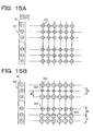
- FIG.15A is the schematic view showing the enlarged recording status recorded by an ideal recording head 32.
- a reference numeral "61" is ink eject ports arranged in the recording head 32.
- ink spots 60 with uniform drop diameter (liquid droplet diameter) are recorded in arrayed state on the recording paper.
- the schematic drawing in the figure is an example recorded with so called full ejection (all eject ports are activated). However, even when recorded with a half tone of 50% ejection, nonuniformity is not generated in this case.
- diameters of drops 62 and 63 ejected from second and (n ⁇ 2)th eject ports are smaller than the other, and drops from (n - 2)th and (n - 1)th eject ports are recorded on positions deviated from ideal positions. More specifically, drops from (n - 2)th eject port are recorded at right-upward positions from ideal centers and drops from (n - 1)th are recorded at left-downward positions from ideal centers.
- Area A indicated in FIG.15B appears as a thin streak on a recorded image.
- Area B also result in a thin streak, because a distance between centers of drops from (n - 1)th and (n - 2)th eject ports is larger than an average distance l 0 between two neighbor drops.
- area C appears a thicker streak than other areas because a distance between centers of drops from (n - 1)th and nth eject ports is smaller than the average distance I 0 between two neighbor drops.
- density nonuniformity appears mainly due to dispersed drop diameters and deviated drops from centers (usually called as the twisted state).
- the density nonuniformity caused by dispersed drop diameters or twisted states as shown in FIG.16B compared with a recorded image by the ideal recording head recorded with a 50% half tone as shown in FIG.16A, can be made inconspicuous, in the following way. For example, when summed dot areas existing in area a surrounded by a broken square in FIG.16B, is adjusted so as to near to summed dot area a surrounded by a broken square in FIG.16A, even an image by recorded by a recording head having characteristics as shown in FIG.16B is judged by human eyes that the recorded image has the same density as that of the image in FIG.16A.
- an area b shown in FIG.16B can be adjusted so as to remove the density nonuniformity.
- FIG.16B illustrates adjusted density compensation results in a model form for explaining simply.
- Reference characters " ⁇ "and " ⁇ " represent dots for compensation.
- This system can be applied to non-eject nozzles, when drop diameters from non-eject nozzles are set nearly zero.
- D(i) ave(i)/AVE
- the density ratio information d(i) obtained in the above mentioned way is processed by a correction table calculating circuit 136 (see FIG.19) of the data conversion unit 94 so that correction tables for respective nozzles are determined. Since this processing procedure is the same as the previous embodiment, further explanations are omitted.
- Non-linear correction tables as shown in FIG.21 can be also employed in accordance with properties of media to be recorded and inks.
- a flow chart for the present case is similar to the flow chart shown FIG.8, but the following steps are omitted; correction table identifying step (S2003), generating different color data (step S2004) and data adding step (S2005).
- Compensated data are transmitted to a ⁇ conversion circuit 95, if required, then converted to binary data by a conversion circuit 96 to binary data and outputted as images.
- the present embodiment is an embodiment where compensations of non-eject statuses by different colors and by the head shading are combined, the compensation can be executed by the same system employed in the head shading of the first embodiment.
- the calculated density ratio information is processed by the correction table calculating circuit 136 in the data conversion unit 94 in the same as the first embodiment and correction tables for respective nozzles are determined.
- the determined correction tables renew contents in the correction table number storing unit 137 and stored information on recording head 854, and the renewed contents are utilized by the data conversion circuit 138.
- Processing operations in the data conversion circuit 138 are basically the same as operations in the above-mentioned embodiment (see FIG.8).
- a different point from the previous embodiment is that when a nozzle indicates the non-eject status, namely the correction table number is #0, contents of the compensation table by different colors for generating compensation data by different colors, are different from the previous embodiment.
- it is desirable not to compensate highlighted portions recorded with relatively low recording duty by different colors since density corrections for respective nozzles are executed by the shading and densities of nnext eighbor nozzles to the non-eject nozzle are corrected so as to compensate the non-eject nozzle. Even when portions recorded with high recording duty are compensated, extents of compensations by different colors can be reduced compared with the above-mentioned embodiment due to above-mentioned effects by density corrections in next neighbor nozzles.
- correction curves for C and M as shown in FIG.5 are expressed as f(x)
- new correction curves by Bk are expressed as ⁇ * f (x ⁇ ⁇ ).
- An example of the new correction curve is plotted in FIG.7.
- the factor " ⁇ " in the new correction curves has a range of 0 ⁇ 1 and the factor " ⁇ " has a range of 0 ⁇ ⁇ ⁇ 255.
- ⁇ is ca. 0.3 and ⁇ is ca. 128.
- data conversions are executed by employing correction tables by different colors shown in FIG.7.
- FIG.3F is the conceptual diagram showing the compensation table so as to correct densities of neighbor nozzles to the non-eject nozzle to raise 1.5 times (corresponds to a correction curve 4b) of the inputted values as shown in FIG.20 compared with the case without compensations (corresponds to a correction curve 4a).
- These compensations recorded with 1.5 times density correspond to FIGs.3A, 3B and 3D.
- Dots up to 4 can be recorded in respective grids shown in FIGs.3A, 3B, 3C and 3D. Therefore, FIG.3A illustrate a uniform pattern to be recorded with low duty, i.e. one dot/grid.
- Nozzles in a recording head to be used for recording dots in FIG.3C are arrayed in a vertical direction of this figure, where a non-eject nozzle corresponds to a third row from the top.
- circles in solid line indicate dot positions recorded by normal nozzles
- circles in fine broken line indicate dot positions to be recorded by non-eject nozzles
- circles in coarse broken line indicate dot positions to be compensated.
- it is desirable that compensations by the next neighbor nozzles to the non-eject nozzle should be recorded with densities of 1.5 times.
- Operating conditions whether compensations by other colors are executed on a selected medium to be recorded or not can be determined and stored in recording apparatus or in a printer driver beforehand. However it is preferable to employ successive procedures comprising steps of recording ink droplets on top end of a medium to be recorded, measuring diameters of formed dots from droplets by the recording apparatus and determining a blotting rate of the medium to be recorded.
- the present invention exhibits its features more effectively when applied to recording heads or recording apparatuses employing ink-jet recording methods, particularly, methods utilizing thermal energy generating means (electro-thermal energy conversion body, laser light source and the like) in order to utilize the generated energy for causing a phase change in ink.
- thermal energy generating means electronic-thermal energy conversion body, laser light source and the like
- the disclosed methods can be applied either to a so-called on-demand typed recording apparatus or to a continuous typed recording apparatus.
- the on-demand typed recording apparatus is effective in the following feature where at least one driving signal corresponding to information to be recorded is applied to an electro-thermal energy conversion body arranged on a sheet or a liquid path where ink is kept so as to raise temperature above a nuclear boiling in a short period by generating energy in the electro-thermal energy conversion body, consequently, bubbles can be formed in accordance with the applied driving signal.
- Ink is ejected via an opening for ejecting by growing/shrinking generated bubbles so that at least one droplet is formed. It is more preferable to adjust the applied signal into a pulse form, since bubbles are instantly and properly grown/shrunk in accordance with the applied signal, namely, liquid (ink) ejection with excellent response in particular is attained.
- Driving signal forms disclosed in the U.S. patent Nos. 4,463,359 and 4,345,262 are suitable to employ as the driving signals with pulse forms.
- an invention relating to temperature raising rate on the above-mentioned thermal active surface are employed, more excellent recording results can be attained.
- the present invention also can be applied to a full line typed recording head capable of recording on a recording medium with a maximum width.
- the full line typed recording head can be constituted either by combining a plurality of recording heads or a monolithically formed recording head.
- the present invention can be applicable to any type of recording heads such as the above-mentioned serial type, an exchangeable tip typed recording head capable of being supplied ink from a recording apparatus, on/to which the recording head is mounted or electrically connected and a cartridge typed recording head where an ink tank is monolithically formed with the recording head.
- a recording head recovery means and auxiliary supporting means as the components to the recording by the present invention, since the present invention can exhibit its features more effectively. More specifically, a capping means against the recording head, a cleaning means, a pressing or sucking means, a spare heating means comprising electro-thermal conversion body, another heating element, a combination of these heating bodies or pre-ejecting means except recording.
- Either one recording head for mono color ink or a plurality of recording head for mono color inks with different densities or a plurality of inks are applicable to the present invention.
- the present invention is applicable not only to a recording apparatus employing a recording mode with a main color such as black, but to a recording apparatus employing a monolithically arranged recording head or a combination of a plurality of recording heads.
- the present invention is quite effective to a recording apparatus employing at least one of the following recording modes: a mode of a plurality of different a full color mode attained by mixing primary colors.
- the present invention dissolves nonuniformity in a recorded image such as white streaks generated by non-eject dots or the present invention makes the nonuniformity caused by non-eject statuses not to be recognized by human eyes, which suppress operating costs of the ink-jet recording apparatus from increasing and further attains effects enabling recording rates raise much faster.
- a recording system comprising a recording apparatus, a recording method and a program to control the recording apparatus for recording a color image on a recording medium by utilizing a recording head on which a plurality of recording elements are arranged.
- the recording system further comprising, a plurality of compensation means having respective own compensation methods to compensate a position to be recorded by a recording element which does not execute a recording operation among said plurality of recording elements; a selection means to select an appropriate compensation means.
- Such recording system can dissolve nonuniformity in the recorded image such as white streaks and the like generated by non-eject dots and can make the nonuniformity be unrecognized by human eyes.
- the recording system by the invention can suppress raising costs of the recording head and can raise recording rates much faster.
Applications Claiming Priority (2)
| Application Number | Priority Date | Filing Date | Title |
|---|---|---|---|
| JP2001340912A JP3890220B2 (ja) | 2001-11-06 | 2001-11-06 | 記録装置及び記録方法 |
| JP2001340912 | 2001-11-06 |
Publications (3)
| Publication Number | Publication Date |
|---|---|
| EP1308281A2 true EP1308281A2 (de) | 2003-05-07 |
| EP1308281A3 EP1308281A3 (de) | 2003-12-03 |
| EP1308281B1 EP1308281B1 (de) | 2006-01-04 |
Family
ID=19155045
Family Applications (1)
| Application Number | Title | Priority Date | Filing Date |
|---|---|---|---|
| EP02024687A Expired - Lifetime EP1308281B1 (de) | 2001-11-06 | 2002-11-05 | Aufzeichnungsgerät und -verfahren und Programm |
Country Status (4)
| Country | Link |
|---|---|
| EP (1) | EP1308281B1 (de) |
| JP (1) | JP3890220B2 (de) |
| AT (1) | ATE314935T1 (de) |
| DE (1) | DE60208484T2 (de) |
Cited By (2)
| Publication number | Priority date | Publication date | Assignee | Title |
|---|---|---|---|---|
| CN102111528B (zh) * | 2009-12-24 | 2013-01-16 | 北京大学 | 一种印刷铺底的方法及装置 |
| CN107234877A (zh) * | 2016-03-29 | 2017-10-10 | 精工爱普生株式会社 | 液滴喷出控制装置、液滴喷出控制方法以及液滴喷出装置 |
Families Citing this family (20)
| Publication number | Priority date | Publication date | Assignee | Title |
|---|---|---|---|---|
| EP1529644B1 (de) * | 2003-11-05 | 2008-04-23 | Océ-Technologies B.V. | Verfahren zur Maskierung von ausgefallenen Druckelementen in einem Drucker |
| JP2006130904A (ja) | 2004-10-05 | 2006-05-25 | Seiko Epson Corp | 印刷装置、印刷プログラム、印刷方法および印刷データ生成装置、印刷データ生成プログラム、印刷データ生成方法、並びに前記プログラムを記録した記録媒体。 |
| JP4311389B2 (ja) | 2004-12-13 | 2009-08-12 | セイコーエプソン株式会社 | 印刷装置、印刷装置制御プログラム及び印刷装置制御方法、並びに印刷用データ生成装置、印刷用データ生成プログラム及び印刷用データ生成方法 |
| JP4434112B2 (ja) | 2004-12-28 | 2010-03-17 | セイコーエプソン株式会社 | 印刷装置、印刷装置制御プログラム及び印刷装置制御方法 |
| JP4552824B2 (ja) | 2005-01-25 | 2010-09-29 | セイコーエプソン株式会社 | 印刷装置、印刷装置制御プログラム及び印刷装置制御方法、並びに印刷用データ生成装置、印刷用データ生成プログラム及び印刷用データ生成方法 |
| JP4487894B2 (ja) | 2005-01-28 | 2010-06-23 | セイコーエプソン株式会社 | 印刷装置 |
| JP4501826B2 (ja) | 2005-01-28 | 2010-07-14 | セイコーエプソン株式会社 | 印刷装置 |
| JP4586712B2 (ja) | 2005-02-03 | 2010-11-24 | セイコーエプソン株式会社 | 印刷装置 |
| JP2006248215A (ja) | 2005-02-14 | 2006-09-21 | Seiko Epson Corp | 印刷装置、印刷装置制御プログラム及び印刷装置制御方法、並びに印刷用データ生成装置、印刷用データ生成プログラム及び印刷用データ生成方法 |
| JP2006264303A (ja) | 2005-02-28 | 2006-10-05 | Seiko Epson Corp | 印刷装置、印刷プログラム、印刷方法および画像処理装置、画像処理プログラム、画像処理方法、ならびに前記プログラムを記録した記録媒体 |
| JP4419947B2 (ja) | 2005-03-01 | 2010-02-24 | セイコーエプソン株式会社 | 印刷装置、印刷装置制御プログラム及び印刷装置制御方法、並びに印刷用データ生成装置、印刷用データ生成プログラム及び印刷用データ生成方法 |
| JP2006289947A (ja) | 2005-03-15 | 2006-10-26 | Seiko Epson Corp | 印刷装置、印刷装置制御プログラム及び印刷装置制御方法、並びに印刷用データ生成装置、印刷用データ生成プログラム及び印刷用データ生成方法 |
| JP4736766B2 (ja) | 2005-03-29 | 2011-07-27 | セイコーエプソン株式会社 | 印刷装置、印刷プログラム、印刷方法および画像処理装置、画像処理プログラム、画像処理方法、並びに前記プログラムを記録した記録媒体 |
| JP4428362B2 (ja) | 2005-08-01 | 2010-03-10 | セイコーエプソン株式会社 | 印刷装置、印刷プログラム、印刷方法および印刷制御装置、印刷制御プログラム、印刷制御方法ならびに前記プログラムを記録した記録媒体 |
| JP2007083704A (ja) | 2005-08-25 | 2007-04-05 | Seiko Epson Corp | 印刷装置、印刷プログラム、印刷方法および画像処理装置、画像処理プログラム、画像処理方法、並びに前記プログラムを記録した記録媒体 |
| JP2007098937A (ja) | 2005-09-12 | 2007-04-19 | Seiko Epson Corp | 印刷装置、印刷プログラム、印刷方法、および画像処理装置、画像処理プログラム、画像処理方法、並びに前記プログラムを記録した記録媒体 |
| JP2007230213A (ja) | 2006-02-01 | 2007-09-13 | Seiko Epson Corp | 印刷装置、印刷装置制御プログラム及び印刷装置制御方法、並びに印刷用データ生成装置、印刷用データ生成プログラム及び印刷用データ生成方法 |
| JP4909321B2 (ja) | 2008-07-09 | 2012-04-04 | 株式会社リコー | 画像処理方法、プログラム、画像処理装置、画像形成装置及び画像形成システム |
| JP2010240924A (ja) * | 2009-04-02 | 2010-10-28 | Seiko Precision Inc | マーキングシステム |
| JP5463806B2 (ja) * | 2009-09-04 | 2014-04-09 | セイコーエプソン株式会社 | 画像処理方法および印刷装置 |
Citations (7)
| Publication number | Priority date | Publication date | Assignee | Title |
|---|---|---|---|---|
| US4313124A (en) | 1979-05-18 | 1982-01-26 | Canon Kabushiki Kaisha | Liquid jet recording process and liquid jet recording head |
| US4345262A (en) | 1979-02-19 | 1982-08-17 | Canon Kabushiki Kaisha | Ink jet recording method |
| US4459600A (en) | 1978-10-31 | 1984-07-10 | Canon Kabushiki Kaisha | Liquid jet recording device |
| JPS59123670A (ja) | 1982-12-28 | 1984-07-17 | Canon Inc | インクジエツトヘツド |
| US4463359A (en) | 1979-04-02 | 1984-07-31 | Canon Kabushiki Kaisha | Droplet generating method and apparatus thereof |
| US4558333A (en) | 1981-07-09 | 1985-12-10 | Canon Kabushiki Kaisha | Liquid jet recording head |
| US4723129A (en) | 1977-10-03 | 1988-02-02 | Canon Kabushiki Kaisha | Bubble jet recording method and apparatus in which a heating element generates bubbles in a liquid flow path to project droplets |
Family Cites Families (5)
| Publication number | Priority date | Publication date | Assignee | Title |
|---|---|---|---|---|
| US5124720A (en) * | 1990-08-01 | 1992-06-23 | Hewlett-Packard Company | Fault-tolerant dot-matrix printing |
| US6039426A (en) * | 1996-08-09 | 2000-03-21 | Hewlett-Packard Company | Simplified print mode selection method and apparatus |
| US6010205A (en) * | 1997-03-12 | 2000-01-04 | Raster Graphics Inc. | Method and apparatus for improved printing |
| EP0983855A3 (de) * | 1998-08-31 | 2000-08-02 | Hewlett-Packard Company | Ersatz von Punkten zur Kompensierung fehlender Tintenstrahldüsen |
| JP3667183B2 (ja) * | 2000-01-28 | 2005-07-06 | キヤノン株式会社 | プリント装置およびプリント媒体種類判別方法 |
-
2001
- 2001-11-06 JP JP2001340912A patent/JP3890220B2/ja not_active Expired - Fee Related
-
2002
- 2002-11-05 EP EP02024687A patent/EP1308281B1/de not_active Expired - Lifetime
- 2002-11-05 DE DE60208484T patent/DE60208484T2/de not_active Expired - Lifetime
- 2002-11-05 AT AT02024687T patent/ATE314935T1/de not_active IP Right Cessation
Patent Citations (8)
| Publication number | Priority date | Publication date | Assignee | Title |
|---|---|---|---|---|
| US4723129A (en) | 1977-10-03 | 1988-02-02 | Canon Kabushiki Kaisha | Bubble jet recording method and apparatus in which a heating element generates bubbles in a liquid flow path to project droplets |
| US4740796A (en) | 1977-10-03 | 1988-04-26 | Canon Kabushiki Kaisha | Bubble jet recording method and apparatus in which a heating element generates bubbles in multiple liquid flow paths to project droplets |
| US4459600A (en) | 1978-10-31 | 1984-07-10 | Canon Kabushiki Kaisha | Liquid jet recording device |
| US4345262A (en) | 1979-02-19 | 1982-08-17 | Canon Kabushiki Kaisha | Ink jet recording method |
| US4463359A (en) | 1979-04-02 | 1984-07-31 | Canon Kabushiki Kaisha | Droplet generating method and apparatus thereof |
| US4313124A (en) | 1979-05-18 | 1982-01-26 | Canon Kabushiki Kaisha | Liquid jet recording process and liquid jet recording head |
| US4558333A (en) | 1981-07-09 | 1985-12-10 | Canon Kabushiki Kaisha | Liquid jet recording head |
| JPS59123670A (ja) | 1982-12-28 | 1984-07-17 | Canon Inc | インクジエツトヘツド |
Cited By (3)
| Publication number | Priority date | Publication date | Assignee | Title |
|---|---|---|---|---|
| CN102111528B (zh) * | 2009-12-24 | 2013-01-16 | 北京大学 | 一种印刷铺底的方法及装置 |
| CN107234877A (zh) * | 2016-03-29 | 2017-10-10 | 精工爱普生株式会社 | 液滴喷出控制装置、液滴喷出控制方法以及液滴喷出装置 |
| CN107234877B (zh) * | 2016-03-29 | 2020-09-29 | 精工爱普生株式会社 | 液滴喷出控制装置、液滴喷出控制方法以及液滴喷出装置 |
Also Published As
| Publication number | Publication date |
|---|---|
| JP2003136702A (ja) | 2003-05-14 |
| ATE314935T1 (de) | 2006-02-15 |
| DE60208484D1 (de) | 2006-03-30 |
| DE60208484T2 (de) | 2006-08-17 |
| EP1308281B1 (de) | 2006-01-04 |
| EP1308281A3 (de) | 2003-12-03 |
| JP3890220B2 (ja) | 2007-03-07 |
Similar Documents
| Publication | Publication Date | Title |
|---|---|---|
| US6953238B2 (en) | Recording apparatus and recording method and program | |
| EP1308281B1 (de) | Aufzeichnungsgerät und -verfahren und Programm | |
| US7101011B2 (en) | Recording apparatus, method and program utilizing compensation dots | |
| EP0527610B1 (de) | Aufzeichnungsgerät | |
| JP4681751B2 (ja) | 記録装置及び記録方法 | |
| EP0763797B1 (de) | Tintenstrahldruckvorrichtung mit Korrektur des Ausdrucks der Bilddaten am Bildrand | |
| JP3245361B2 (ja) | 画像記録装置および画像記録システム | |
| JPH0664157A (ja) | 画像記録装置 | |
| EP1679191B1 (de) | Druckverfahren und drucksystem | |
| US20020097412A1 (en) | Image processing method, printer and storage medium | |
| EP0645246B1 (de) | Tintenstrahlgerät und Aufzeichnungsverfahren | |
| JP3184744B2 (ja) | 解像度変換可能なインクジェット記録方法 | |
| JP3205573B2 (ja) | インクジェット記録装置 | |
| JPH06328675A (ja) | 画像形成装置 | |
| JP3160318B2 (ja) | インクジェット記録装置 | |
| JP7482691B2 (ja) | 画像処理装置、画像処理方法、テストパターン | |
| JP4300742B2 (ja) | 画像データの階調数を変換する画像処理装置 | |
| JP3368264B2 (ja) | 解像度変換可能なインクジェット記録方法 | |
| JP2011031633A (ja) | 記録装置及び記録方法 | |
| JP2986116B2 (ja) | 記録装置 | |
| JPH04115952A (ja) | インクジエツト記録装置 | |
| JPH04241958A (ja) | 画像記録装置 |
Legal Events
| Date | Code | Title | Description |
|---|---|---|---|
| PUAI | Public reference made under article 153(3) epc to a published international application that has entered the european phase |
Free format text: ORIGINAL CODE: 0009012 |
|
| AK | Designated contracting states |
Designated state(s): AT BE BG CH CY CZ DE DK EE ES FI FR GB GR IE IT LI LU MC NL PT SE SK TR |
|
| AX | Request for extension of the european patent |
Extension state: AL LT LV MK RO SI |
|
| PUAL | Search report despatched |
Free format text: ORIGINAL CODE: 0009013 |
|
| AK | Designated contracting states |
Kind code of ref document: A3 Designated state(s): AT BE BG CH CY CZ DE DK EE ES FI FR GB GR IE IT LI LU MC NL PT SE SK TR |
|
| AX | Request for extension of the european patent |
Extension state: AL LT LV MK RO SI |
|
| RIC1 | Information provided on ipc code assigned before grant |
Ipc: 7B 41J 11/00 B Ipc: 7B 41J 2/165 B Ipc: 7B 41J 2/05 A |
|
| 17P | Request for examination filed |
Effective date: 20040414 |
|
| AKX | Designation fees paid |
Designated state(s): AT BE BG CH CY CZ DE DK EE ES FI FR GB GR IE IT LI LU MC NL PT SE SK TR |
|
| 17Q | First examination report despatched |
Effective date: 20040803 |
|
| GRAP | Despatch of communication of intention to grant a patent |
Free format text: ORIGINAL CODE: EPIDOSNIGR1 |
|
| GRAS | Grant fee paid |
Free format text: ORIGINAL CODE: EPIDOSNIGR3 |
|
| GRAA | (expected) grant |
Free format text: ORIGINAL CODE: 0009210 |
|
| AK | Designated contracting states |
Kind code of ref document: B1 Designated state(s): AT BE BG CH CY CZ DE DK EE ES FI FR GB GR IE IT LI LU MC NL PT SE SK TR |
|
| PG25 | Lapsed in a contracting state [announced via postgrant information from national office to epo] |
Ref country code: SK Free format text: LAPSE BECAUSE OF FAILURE TO SUBMIT A TRANSLATION OF THE DESCRIPTION OR TO PAY THE FEE WITHIN THE PRESCRIBED TIME-LIMIT Effective date: 20060104 Ref country code: NL Free format text: LAPSE BECAUSE OF FAILURE TO SUBMIT A TRANSLATION OF THE DESCRIPTION OR TO PAY THE FEE WITHIN THE PRESCRIBED TIME-LIMIT Effective date: 20060104 Ref country code: LI Free format text: LAPSE BECAUSE OF FAILURE TO SUBMIT A TRANSLATION OF THE DESCRIPTION OR TO PAY THE FEE WITHIN THE PRESCRIBED TIME-LIMIT Effective date: 20060104 Ref country code: BE Free format text: LAPSE BECAUSE OF FAILURE TO SUBMIT A TRANSLATION OF THE DESCRIPTION OR TO PAY THE FEE WITHIN THE PRESCRIBED TIME-LIMIT Effective date: 20060104 Ref country code: IT Free format text: LAPSE BECAUSE OF FAILURE TO SUBMIT A TRANSLATION OF THE DESCRIPTION OR TO PAY THE FEE WITHIN THE PRESCRIBED TIME-LIMIT;WARNING: LAPSES OF ITALIAN PATENTS WITH EFFECTIVE DATE BEFORE 2007 MAY HAVE OCCURRED AT ANY TIME BEFORE 2007. THE CORRECT EFFECTIVE DATE MAY BE DIFFERENT FROM THE ONE RECORDED. Effective date: 20060104 Ref country code: CH Free format text: LAPSE BECAUSE OF FAILURE TO SUBMIT A TRANSLATION OF THE DESCRIPTION OR TO PAY THE FEE WITHIN THE PRESCRIBED TIME-LIMIT Effective date: 20060104 Ref country code: AT Free format text: LAPSE BECAUSE OF FAILURE TO SUBMIT A TRANSLATION OF THE DESCRIPTION OR TO PAY THE FEE WITHIN THE PRESCRIBED TIME-LIMIT Effective date: 20060104 Ref country code: FI Free format text: LAPSE BECAUSE OF FAILURE TO SUBMIT A TRANSLATION OF THE DESCRIPTION OR TO PAY THE FEE WITHIN THE PRESCRIBED TIME-LIMIT Effective date: 20060104 |
|
| REG | Reference to a national code |
Ref country code: GB Ref legal event code: FG4D |
|
| REG | Reference to a national code |
Ref country code: CH Ref legal event code: EP |
|
| REG | Reference to a national code |
Ref country code: IE Ref legal event code: FG4D |
|
| REF | Corresponds to: |
Ref document number: 60208484 Country of ref document: DE Date of ref document: 20060330 Kind code of ref document: P |
|
| PG25 | Lapsed in a contracting state [announced via postgrant information from national office to epo] |
Ref country code: DK Free format text: LAPSE BECAUSE OF FAILURE TO SUBMIT A TRANSLATION OF THE DESCRIPTION OR TO PAY THE FEE WITHIN THE PRESCRIBED TIME-LIMIT Effective date: 20060404 Ref country code: BG Free format text: LAPSE BECAUSE OF FAILURE TO SUBMIT A TRANSLATION OF THE DESCRIPTION OR TO PAY THE FEE WITHIN THE PRESCRIBED TIME-LIMIT Effective date: 20060404 Ref country code: SE Free format text: LAPSE BECAUSE OF FAILURE TO SUBMIT A TRANSLATION OF THE DESCRIPTION OR TO PAY THE FEE WITHIN THE PRESCRIBED TIME-LIMIT Effective date: 20060404 |
|
| PG25 | Lapsed in a contracting state [announced via postgrant information from national office to epo] |
Ref country code: ES Free format text: LAPSE BECAUSE OF FAILURE TO SUBMIT A TRANSLATION OF THE DESCRIPTION OR TO PAY THE FEE WITHIN THE PRESCRIBED TIME-LIMIT Effective date: 20060415 |
|
| PG25 | Lapsed in a contracting state [announced via postgrant information from national office to epo] |
Ref country code: PT Free format text: LAPSE BECAUSE OF FAILURE TO SUBMIT A TRANSLATION OF THE DESCRIPTION OR TO PAY THE FEE WITHIN THE PRESCRIBED TIME-LIMIT Effective date: 20060605 |
|
| NLV1 | Nl: lapsed or annulled due to failure to fulfill the requirements of art. 29p and 29m of the patents act | ||
| REG | Reference to a national code |
Ref country code: CH Ref legal event code: PL |
|
| ET | Fr: translation filed | ||
| PG25 | Lapsed in a contracting state [announced via postgrant information from national office to epo] |
Ref country code: IE Free format text: LAPSE BECAUSE OF NON-PAYMENT OF DUE FEES Effective date: 20061106 |
|
| PLBE | No opposition filed within time limit |
Free format text: ORIGINAL CODE: 0009261 |
|
| STAA | Information on the status of an ep patent application or granted ep patent |
Free format text: STATUS: NO OPPOSITION FILED WITHIN TIME LIMIT |
|
| PG25 | Lapsed in a contracting state [announced via postgrant information from national office to epo] |
Ref country code: MC Free format text: LAPSE BECAUSE OF NON-PAYMENT OF DUE FEES Effective date: 20061130 |
|
| 26N | No opposition filed |
Effective date: 20061005 |
|
| PG25 | Lapsed in a contracting state [announced via postgrant information from national office to epo] |
Ref country code: GR Free format text: LAPSE BECAUSE OF FAILURE TO SUBMIT A TRANSLATION OF THE DESCRIPTION OR TO PAY THE FEE WITHIN THE PRESCRIBED TIME-LIMIT Effective date: 20060405 Ref country code: CZ Free format text: LAPSE BECAUSE OF FAILURE TO SUBMIT A TRANSLATION OF THE DESCRIPTION OR TO PAY THE FEE WITHIN THE PRESCRIBED TIME-LIMIT Effective date: 20060104 |
|
| PG25 | Lapsed in a contracting state [announced via postgrant information from national office to epo] |
Ref country code: EE Free format text: LAPSE BECAUSE OF FAILURE TO SUBMIT A TRANSLATION OF THE DESCRIPTION OR TO PAY THE FEE WITHIN THE PRESCRIBED TIME-LIMIT Effective date: 20060104 |
|
| PG25 | Lapsed in a contracting state [announced via postgrant information from national office to epo] |
Ref country code: TR Free format text: LAPSE BECAUSE OF FAILURE TO SUBMIT A TRANSLATION OF THE DESCRIPTION OR TO PAY THE FEE WITHIN THE PRESCRIBED TIME-LIMIT Effective date: 20060104 Ref country code: LU Free format text: LAPSE BECAUSE OF NON-PAYMENT OF DUE FEES Effective date: 20061105 |
|
| PG25 | Lapsed in a contracting state [announced via postgrant information from national office to epo] |
Ref country code: CY Free format text: LAPSE BECAUSE OF FAILURE TO SUBMIT A TRANSLATION OF THE DESCRIPTION OR TO PAY THE FEE WITHIN THE PRESCRIBED TIME-LIMIT Effective date: 20060104 |
|
| PGFP | Annual fee paid to national office [announced via postgrant information from national office to epo] |
Ref country code: IT Payment date: 20121107 Year of fee payment: 11 |
|
| PGFP | Annual fee paid to national office [announced via postgrant information from national office to epo] |
Ref country code: FR Payment date: 20121214 Year of fee payment: 11 |
|
| REG | Reference to a national code |
Ref country code: FR Ref legal event code: ST Effective date: 20140731 |
|
| PG25 | Lapsed in a contracting state [announced via postgrant information from national office to epo] |
Ref country code: IT Free format text: LAPSE BECAUSE OF NON-PAYMENT OF DUE FEES Effective date: 20131105 |
|
| PG25 | Lapsed in a contracting state [announced via postgrant information from national office to epo] |
Ref country code: FR Free format text: LAPSE BECAUSE OF NON-PAYMENT OF DUE FEES Effective date: 20131202 |
|
| PGFP | Annual fee paid to national office [announced via postgrant information from national office to epo] |
Ref country code: GB Payment date: 20151125 Year of fee payment: 14 Ref country code: DE Payment date: 20151130 Year of fee payment: 14 |
|
| REG | Reference to a national code |
Ref country code: DE Ref legal event code: R119 Ref document number: 60208484 Country of ref document: DE |
|
| GBPC | Gb: european patent ceased through non-payment of renewal fee |
Effective date: 20161105 |
|
| PG25 | Lapsed in a contracting state [announced via postgrant information from national office to epo] |
Ref country code: GB Free format text: LAPSE BECAUSE OF NON-PAYMENT OF DUE FEES Effective date: 20161105 Ref country code: DE Free format text: LAPSE BECAUSE OF NON-PAYMENT OF DUE FEES Effective date: 20170601 |