EP1307152B1 - Gerät und fixiermittel zur fixierung von knochenfragmenten und knochenbrüchen - Google Patents
Gerät und fixiermittel zur fixierung von knochenfragmenten und knochenbrüchen Download PDFInfo
- Publication number
- EP1307152B1 EP1307152B1 EP01958732A EP01958732A EP1307152B1 EP 1307152 B1 EP1307152 B1 EP 1307152B1 EP 01958732 A EP01958732 A EP 01958732A EP 01958732 A EP01958732 A EP 01958732A EP 1307152 B1 EP1307152 B1 EP 1307152B1
- Authority
- EP
- European Patent Office
- Prior art keywords
- pin
- sleeve
- end portion
- ready position
- side opening
- Prior art date
- Legal status (The legal status is an assumption and is not a legal conclusion. Google has not performed a legal analysis and makes no representation as to the accuracy of the status listed.)
- Expired - Lifetime
Links
- 210000000988 bone and bone Anatomy 0.000 title claims abstract description 19
- 239000012634 fragment Substances 0.000 title claims abstract description 17
- 208000010392 Bone Fractures Diseases 0.000 title claims abstract description 6
- 210000003739 neck Anatomy 0.000 claims abstract description 9
- 210000001694 thigh bone Anatomy 0.000 claims abstract description 9
- 238000003780 insertion Methods 0.000 claims description 4
- 230000037431 insertion Effects 0.000 claims description 4
- 239000000463 material Substances 0.000 description 4
- 239000007769 metal material Substances 0.000 description 3
- 238000006073 displacement reaction Methods 0.000 description 1
- 238000000605 extraction Methods 0.000 description 1
- 210000002436 femur neck Anatomy 0.000 description 1
Images

Classifications
-
- A—HUMAN NECESSITIES
- A61—MEDICAL OR VETERINARY SCIENCE; HYGIENE
- A61B—DIAGNOSIS; SURGERY; IDENTIFICATION
- A61B17/00—Surgical instruments, devices or methods
- A61B17/56—Surgical instruments or methods for treatment of bones or joints; Devices specially adapted therefor
- A61B17/58—Surgical instruments or methods for treatment of bones or joints; Devices specially adapted therefor for osteosynthesis, e.g. bone plates, screws or setting implements
- A61B17/68—Internal fixation devices, including fasteners and spinal fixators, even if a part thereof projects from the skin
-
- A—HUMAN NECESSITIES
- A61—MEDICAL OR VETERINARY SCIENCE; HYGIENE
- A61B—DIAGNOSIS; SURGERY; IDENTIFICATION
- A61B17/00—Surgical instruments, devices or methods
- A61B17/56—Surgical instruments or methods for treatment of bones or joints; Devices specially adapted therefor
- A61B17/58—Surgical instruments or methods for treatment of bones or joints; Devices specially adapted therefor for osteosynthesis, e.g. bone plates, screws or setting implements
- A61B17/68—Internal fixation devices, including fasteners and spinal fixators, even if a part thereof projects from the skin
- A61B17/72—Intramedullary devices, e.g. pins or nails
- A61B17/7233—Intramedullary devices, e.g. pins or nails with special means of locking the nail to the bone
- A61B17/7258—Intramedullary devices, e.g. pins or nails with special means of locking the nail to the bone with laterally expanding parts, e.g. for gripping the bone
- A61B17/7266—Intramedullary devices, e.g. pins or nails with special means of locking the nail to the bone with laterally expanding parts, e.g. for gripping the bone with fingers moving radially outwardly
-
- A—HUMAN NECESSITIES
- A61—MEDICAL OR VETERINARY SCIENCE; HYGIENE
- A61B—DIAGNOSIS; SURGERY; IDENTIFICATION
- A61B17/00—Surgical instruments, devices or methods
- A61B17/56—Surgical instruments or methods for treatment of bones or joints; Devices specially adapted therefor
- A61B17/58—Surgical instruments or methods for treatment of bones or joints; Devices specially adapted therefor for osteosynthesis, e.g. bone plates, screws or setting implements
- A61B17/68—Internal fixation devices, including fasteners and spinal fixators, even if a part thereof projects from the skin
- A61B17/74—Devices for the head or neck or trochanter of the femur
-
- A—HUMAN NECESSITIES
- A61—MEDICAL OR VETERINARY SCIENCE; HYGIENE
- A61B—DIAGNOSIS; SURGERY; IDENTIFICATION
- A61B17/00—Surgical instruments, devices or methods
- A61B17/34—Trocars; Puncturing needles
- A61B2017/348—Means for supporting the trocar against the body or retaining the trocar inside the body
- A61B2017/3482—Means for supporting the trocar against the body or retaining the trocar inside the body inside
- A61B2017/3484—Anchoring means, e.g. spreading-out umbrella-like structure
- A61B2017/3488—Fixation to inner organ or inner body tissue
-
- Y—GENERAL TAGGING OF NEW TECHNOLOGICAL DEVELOPMENTS; GENERAL TAGGING OF CROSS-SECTIONAL TECHNOLOGIES SPANNING OVER SEVERAL SECTIONS OF THE IPC; TECHNICAL SUBJECTS COVERED BY FORMER USPC CROSS-REFERENCE ART COLLECTIONS [XRACs] AND DIGESTS
- Y10—TECHNICAL SUBJECTS COVERED BY FORMER USPC
- Y10S—TECHNICAL SUBJECTS COVERED BY FORMER USPC CROSS-REFERENCE ART COLLECTIONS [XRACs] AND DIGESTS
- Y10S606/00—Surgery
- Y10S606/907—Composed of particular material or coated
Definitions
- the present invention relates to a device at fixing means for fixation of bone fragments at bone fractures
- the fixing means preferably is a spike for thigh--bone necks for fixation of bone fragments at fractures of the thigh-bone neck
- the fixing means comprises a sleeve which is open at the rear for insertion of a pin into a ready position, wherein the sleeve defines an elongated space with two opposite wall surfaces, namely a first longitudinal wall surface in which there is provided a side opening and a longitudinal second wall surface from which a guide surface extends in an inclined forward direction to a front edge of the side opening, and wherein the guide surface is provided to guide a front, preferably curved end portion of the pin to force its way out through the side opening when said pin is displaced in a forward direction relative to the sleeve.
- Fixing means of the abovementioned type are known from SE 431 053 ( US 4 498 468 ) and have operated satisfactory for many years.
- the object of the present invention has been to eliminate this problem and this is arrived at by providing the abovementioned device with the characterizing features of subsequent claim 1.
- the pin is prevented from unintentional movement out of a ready position and/or is it ensured that the end portion of the pin gets an advantageous curvature such that a stable fixation of the bone fragment is obtained and the likelihood that said pin penetrates the bone fragment is reduced.
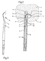
- the fixing means 1 illustrated in the drawings is adapted for fixation of bone fragments at bone fractures.
- the fixing means 1 is a spike for thigh-bone necks, a collum spike, for fixation of bone fragments 2, 3 at fractures 4 of the thigh-bone neck.
- the spike 1 comprises a sleeve 5 with an elongated space 6 which is open at the rear for insertion of a pin 7.
- the elongated space 6 has a circular or substantially circular cross section.
- the sleeve 5 has a first longitudinal wall surface 8 and opposite thereto, a second longitudinal wall surface 9.
- first longitudinal wall surface 8 there is provided a side opening 10 and from a front edge 13 of said side opening 10, a guide surface 12 protrudes in a backwards inclined direction to the second longitudinal wall surface 9.
- the pin 7 has a front end portion 7f which preferably is curved. This front end portion 7f is adapted to be guided by the guide surface 12 such that it is forced out of the space 6 through the side opening 10 and into adjacent bone fragment 3.
- a front part 7a of the pin 7 close to its front end portion 7f extends in an inclined forward direction towards front parts 9a of the second longitudinal wall surface 9 and is preferably adapted to have contact with said front parts 9a at the guide surface 12 when the pin 7 is in a ready position B (see fig. 1) from which it can be driven farther into the elongated space 6 in order to force the front end portion 7f out through the side opening 10.
- a ready position B see fig. 1
- contact members 7b between said front part 7a and an intermediate part 7d of the pin 7 are in contact with the first longitudinal wall surface 8 behind the side opening 10.
- the front end portion 7f of the pin 7 preferably has a height h which is greater than the distance a between the first and second longitudinal wall surfaces 8 and 9.
- the height h of the front end portion 7f may be about 4,5 mm while the distance a is about 4 mm.
- the pin 7 is capable of being bent such that the front end portion 7f can be inserted into the elongated space 6 when the pin 7 is moved to the ready position B. When the pin 7 has reached the ready position B, the front end portion 7f can snap into the side opening 10.
- said front end portion 7f of the pin 7 preferably is in contact with central parts of the guide surface 12 about halfway between the front edge 13 of the side opening 10 and the second longitudinal wall surface 9.
- the front end portion 7f of the pin 7 projects preferably into the side opening 10, but not out of the sleeve 5 beyond its outer profiles when said pin 7 is in the ready position B.
- the pin 7 is designed relative to the space 6 in the sleeve 5 such that it in the ready position B does not move unintentionally out of said space 6 relative to said sleeve 5.
- the pin 7 is adapted to be driven into the sleeve 5 by means of a driving or actuator instrument 15.
- This instrument may comprise three members schematically illustrated with broken lines in fig. 1, namely an outer sleeve 15a which can be brought to engage the rear edge 23 of the sleeve 5 such that said outer sleeve 15a can not turn or rotate relative to the sleeve 5.
- Said outer sleeve 15a can be held in this position by means of an inner sleeve 15b having outer threads which permit meshing of said outer sleeve with inner threads in the sleeve 5.
- the driving instrument 15 further comprises a driving or actuator unit 15c which has outer threads permitting it to be secured to inner threads in the inner sleeve 15b. Since thereby the driving unit 15c is in contact with the rear edge 17 of the pin 7, it will drive or force the pin 7 into the space 6 in the sleeve 5 and thus, press the front end portion 7f of the pin 7 out of the side opening 10, whereby said front end portion 7f is deformed.
- a driving or actuator unit 15c which has outer threads permitting it to be secured to inner threads in the inner sleeve 15b. Since thereby the driving unit 15c is in contact with the rear edge 17 of the pin 7, it will drive or force the pin 7 into the space 6 in the sleeve 5 and thus, press the front end portion 7f of the pin 7 out of the side opening 10, whereby said front end portion 7f is deformed.
- the pin 7 is also designed relative to the space 6 of the sleeve 5 such that it can not rotate about its longitudinal axis L if and/or when parts of the driving instrument 15 come in contact therewith when said parts are turned or rotated. This can be achieved by bringing the front end portion 7f of the pin 7 to engage the side opening 10 when said pin 7 is in its ready position B.
- the pin 7 preferably has elastic properties or at least a front part 7a thereof has elastic properties.
- the pin 7 may e.g. consist of such metallic material that it has elastically resilient properties.
- the pin 7 may have an original shape U (see fig. 3) which is such relative to the shape of the elongated space 6 in the sleeve 5 that said pin 7, during insertion into said elongated space 6 in the sleeve 5, through deformation is brought into such a strained or stretched condition S (see fig. 1) that it moves or is moved unintentionally relative to the sleeve 5.
- U original shape U
- S a strained or stretched condition
- the pin 7 is provided to slide against the front part 9a of the second longitudinal wall 9, lying closest to the guide surface 12 when the pin 7 is driven into the elongated space 6. Rear parts 7e of the pin 7 are in contact with the second longitudinal wall 9 of the sleeve 5 when the pin 7 is in the ready position B.
- the front end portion 7f of the pin 7 is preferably in contact with the guide surface 12 a short distance within the side opening 10, such that when the front end portion 7f is forced out through the side opening 10, it assumes a curved shape along its entire or at least the major part of its length.
- the pin 7 may, in its original shape U, have a straight or substantially straight rear part 7e and the front part 7a may be straight or substantially straight and directed obliquely forward/sideways relative to the rear part 7e or the pin 7 may e.g. have an S-shape as is shown in fig. 3.
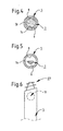
- the front part 7a of the pin 7 may have a circular segment-shaped cross section (see fig. 5) and its rear part 7e a circular cross section (see fig. 4). At the contact part 7b, the circular segment-shaped cross section transforms into the circular cross section. Furthermore, the rear part 7e of the pin 7 may be in contact with the second longitudinal wall 9 through a contact part 7c.
- the pin 7 preferably has such a length relative to the length of the elongated space 6 of the sleeve 5 that the rear edge 17 of the pin 7 is situated edge-to-edge with the rear edge 23 of the sleeve or within said rear edge 23 when the pin 7 is fully driven into the sleeve 5. This is advantageous since the pin 7 after finished driving or actuator operation hereby does not project at the rear of the sleeve 5, whereby the risk for tenderness of the patient is reduced.
- the pin 7 is provided with a threaded portion (not shown) which after finished driving or actuator operation is located inside the sleeve 5 and which is adapted for cooperation with a correspondingly threaded portion (not shown) on an extractor unit (not shown) for extraction or removal of the pin 7 from the bone fragment 3.
- front parts 27 of the sleeve 5 may have external threads for securing the sleeve 5 to the bone fragment 3.
- the outer diameter of the external threads of the front parts 27 may correspond with or substantially correspond with the outer diameter of unthreaded parts of the sleeve 5 behind said front parts 27.
- the pin 7 will thus remain in a ready position B until its front end portion 7f has been driven or forced into surrounding bone material 2.
- Another advantage is that the front end portion 7f of the pin 7 will slide against large parts of the guide surface 12 during its displacement, whereby said pin assumes an advantageous curved shape along its entire or almost entire length outside the side opening 10.
- the fixing means 1 can be used for bone fractures on other locations than the thigh-bone neck (neck of the femur)
- the sleeve 5 may be of metal material or another suitable material
- the pin 7 may be of another material than metallic material
- the sleeve 5 as well as the pin 7 may have other shapes than those illustrated and yet have the same or similar functions as described above.
Landscapes
- Health & Medical Sciences (AREA)
- Orthopedic Medicine & Surgery (AREA)
- Surgery (AREA)
- Life Sciences & Earth Sciences (AREA)
- Molecular Biology (AREA)
- Public Health (AREA)
- Engineering & Computer Science (AREA)
- Biomedical Technology (AREA)
- Heart & Thoracic Surgery (AREA)
- Medical Informatics (AREA)
- Neurology (AREA)
- Animal Behavior & Ethology (AREA)
- General Health & Medical Sciences (AREA)
- Nuclear Medicine, Radiotherapy & Molecular Imaging (AREA)
- Veterinary Medicine (AREA)
- Surgical Instruments (AREA)
- Orthopedics, Nursing, And Contraception (AREA)
- Prostheses (AREA)
- Apparatus For Radiation Diagnosis (AREA)
- Medicines Containing Antibodies Or Antigens For Use As Internal Diagnostic Agents (AREA)
- Materials For Medical Uses (AREA)
- Mechanical Pencils And Projecting And Retracting Systems Therefor, And Multi-System Writing Instruments (AREA)
Claims (21)
- Vorrichtung an einem Fixiermittel zum Fixieren von Knochenfragmenten bei Knochenbrüchen,
wobei das Fixiermittel (1) vorzugsweise ein Dorn für Oberschenkelhälse zum Fixieren von Knochenfragmenten (2, 3) bei Brüchen (4) des Oberschenkelhalses ist,
wobei das Fixiermittel (1) eine Hülse (5) umfasst, welche am hinteren Ende offen ist zum Einführen eines Stifts (7) in eine Bereitschaftsposition (B),
wobei die Hülse (5) einen länglichen Raum mit zwei einander gegenüberliegenden Wandflächen (8, 9), nämlich einer ersten Längswandfläche (8), in der eine seitliche Öffnung (10) vorgesehen ist, und einer zweiten Längswandfläche (9), von der aus sich eine Führungsfläche (12) nach vorne geneigt zu einer vorderen Kante (13) der seitlichen Öffnung (10) erstreckt, begrenzt, und
wobei die Führungsfläche (12) vorgesehen ist, um einen vorderen, vorzugsweise gekrümmten Endabschnitt (7f) des Stifts (7) zu führen, um sich den Weg durch die seitliche Öffnung (10) hinaus zu bahnen, wenn der Stift (7) relativ zur Hülse (5) nach vorne verschoben wird,
dadurch gekennzeichnet,
dass der Stift (7) an den vorderen Endabschnitt (7f) angrenzend einen vorderen Teil (7a) aufweist, welcher relativ zu einem hinteren Teil (7e) desselben schräg nach vorne und in Richtung auf vordere Teile (9a) der zweiten Wandfläche (9) nahe der Führungsfläche (12) gerichtet ist, wenn sich der Stift (7) in der Hülse (5) in einer Bereitschaftsposition (B) befindet. - Vorrichtung gemäß Anspruch 1, dadurch gekennzeichnet, dass der vordere Teil (7a) des Stifts (7) mit den vorderen Teilen (9a) der zweiten Wandfläche (9)
in Berührung ist, wenn sich der Stift (7) in Bereitschaftsposition (B) befindet. - Vorrichtung gemäß Anspruch 1 oder 2, dadurch gekennzeichnet, dass der Stift (7) so gestaltet ist, dass sein vorderer Teil (7a) gegen die vorderen Teile (9a) der zweiten Wandfläche (9) gleitet, wenn er in den länglichen Raum (6) der Hülse (5) getrieben oder gedrängt wird, um den vorderen Endabschnitt (7f) des Stifts (7) dazu zu bringen, aus der seitlichen Öffnung (10) herauszuragen oder sich seinen Weg aus der seitlichen Öffnung (10) hinaus zu bahnen.
- Vorrichtung gemäß einem der vorangehenden Ansprüche, dadurch gekennzeichnet, dass der vordere Endabschnitt (7f) des Stifts (7) mit der seitlichen Öffnung (10) in Eingriff kommt, wenn sich der Stift (7) in Bereitschaftsposition (B) befindet.
- Vorrichtung gemäß Anspruch 4, dadurch gekennzeichnet,
dass der Stift (7) eine ursprüngliche Form (U) hat, bei der eine Höhe (h) des vorderen Endabschnitts (7f) größer ist als der Abstand (a) zwischen der ersten und der zweiten Längswandfläche (8, 9),
dass der Stift (7) so gebogen werden kann, dass der vordere Endabschnitt (7f) in die Hülse (5) eingeführt werden kann, wenn der Stift (7) in die Bereitschaftsposition (B) darin bewegt wird, und
dass der Stift (7) solche elastischen Eigenschaften hat, dass der vordere Endabschnitt (7f) in die seitliche Öffnung (10) einrastet, nachdem er dorthin bewegt wurde. - Vorrichtung gemäß Anspruch 4 oder 5, dadurch gekennzeichnet, dass sich der vordere Endabschnitt (7f) des Stifts (7) innerhalb des äußeren Profils der Hülse (5) befindet, wenn er mit der seitlichen Öffnung (10) in Eingriff kommt.
- Vorrichtung gemäß einem der vorangehenden Ansprüche, wobei der Stift (7) einen hinteren Teil (7e) aufweist, der vorne in ein Zwischenstück (7d) übergeht, welches wiederum vorne in den vorderen Teil (7a) übergeht, dadurch gekennzeichnet, dass dieses Zwischenstück (7d) schräg nach vorne in Richtung auf die erste Längswandfläche (8) gerichtet ist, wenn sich der Stift (7) in Bereitschaftsposition (B) befindet.
- Vorrichtung gemäß Anspruch 7, dadurch gekennzeichnet, dass ein Kontaktteil (7b) zwischen dem Zwischenstück (7d) und dem vorderen Teil (7a) mit der ersten Wandfläche (8) in Berührung ist und dass der hintere Teil (7e) mit der zweiten Wandfläche (9) in Berührung ist, wenn sich der Stift (7) in Bereitschaftsposition (B) befindet.
- Vorrichtung gemäß einem der vorangehenden Ansprüche, dadurch gekennzeichnet, dass der vordere Endabschnitt (7f) des Stifts (7) mit der Führungsfläche (12) in Berührung ist, wenn sich der Stift (7) in Bereitschaftsposition (B) befindet.
- Vorrichtung gemäß einem der vorangehenden Ansprüche, dadurch gekennzeichnet, dass der vordere Endabschnitt (7f) des Stifts (7) mit mittleren Teilen der Führungsfläche (12) ungefähr auf halbem Weg zwischen der vorderen Kante (13) der seitlichen Öffnung (10) und der zweiten Längswandfläche (9), in Berührung ist, wenn sich der Stift (7) in Bereitschaftsposition (B) befindet und/oder wenn der Stift (7) in den länglichen Raum (6) getrieben wird, um den vorderen Endabschnitt (7f) desselben dazu zu bringen, sich seinen Weg durch die seitliche Öffnung (10) zu bahnen.
- Vorrichtung gemäß einem der vorangehenden Ansprüche, dadurch gekennzeichnet, dass der Stift (7) einen hinteren Teil (7e) und ein Zwischenstück (7d) mit kreisförmigem Querschnitt sowie einen vorderen Teil (7a) mit kreissegmentförmigem Querschnitt hat.
- Vorrichtung gemäß einem der vorangehenden Ansprüche, dadurch gekenn-zeichnet, dass der Stift (7) in Bereitschaftsposition (B) so vorgesehen ist, dass er sich nicht relativ zur Hülse (5) um seine Längsachse (L) dreht oder rotiert und/oder gedreht werden kann.
- Vorrichtung gemäß einem der vorangehenden Ansprüche, dadurch gekennzeichnet, dass der Stift (7) in Bereitschaftsposition (B) so vorgesehen ist, dass er nicht relativ zur Hülse (5) um seine Längsachse (L) rotieren kann, wenn von Teilen eines Eintreib- oder Betätigungsinstruments (15) ausgehende Drehkräfte auf ihn einwirken.
- Vorrichtung gemäß einem der vorangehenden Ansprüche, dadurch gekennzeichnet, dass der Stift (7) in Bereitschaftsposition (B) in gespanntem oder gedehntem Zustand montiert wird.
- Vorrichtung gemäß einem der vorangehenden Ansprüche, dadurch gekennzeichnet, dass der Stift (7) eine ursprüngliche Form (U) hat, die so von der Form des länglichen Raums (6) der Hülse (5) abweicht, dass der Stift (7) durch Verformung gespannt oder gedehnt wird, wenn er im länglichen Raum (6) in eine Bereitschaftsposition (B) eingeführt wird.
- Vorrichtung gemäß einem der vorangehenden Ansprüche, dadurch gekennzeichnet, dass der vordere Endabschnitt (7f) des Stifts (7) so vorgesehen ist, dass er als gekrümmter vorderer Endabschnitt (7f) entlang seiner gesamten oder im Wesentlichen gesamten Länge aus der seitlichen Öffnung (10) gedrängt wird.
- Vorrichtung gemäß einem der vorangehenden Ansprüche, dadurch gekennzeichnet, dass der Stift (7) in einer ursprünglichen Form (U) einen geraden oder im Wesentlichen geraden hinteren Teil (7e) hat und einen geraden oder im Wesentlichen geraden vorderen Teil (7a) hat, der relativ zum hinteren Teil (7e) vorwärts/seitwärts gerichtet ist.
- Vorrichtung gemäß einem der vorangehenden Ansprüche, dadurch gekennzeichnet, dass der Stift (7) oder zumindest ein vorderer Teil (7a) desselben elastische Eigenschaften hat.
- Vorrichtung gemäß einem der vorangehenden Ansprüche, dadurch gekennzeichnet, dass der Stift (7) relativ zur Länge des länglichen Raums (6) der Hülse (5) eine solche Länge hat, dass eine hintere Kante (17) des Stifts (7) mit einer hinteren Kante (23) der Hülse (5) Kante an Kante oder innerhalb dieser hinteren Kante (23) liegt, wenn der Stift (7) vollständig in die Hülse (5) hinein getrieben wird, so dass der Stift (7) nach durchgeführtem Eintreib- oder Betätigungsvorgang nicht hinten aus der Hülse (5) herausragt.
- Vorrichtung gemäß einem der vorangehenden Ansprüche, dadurch gekennzeichnet, dass vordere Teile (27) der Hülse (5) mit Außengewinden versehen sind, um diese vorderen Teile (27) an einem benachbarten Knochenfragment (3) zu befestigen.
- Vorrichtung gemäß Anspruch 20, dadurch gekennzeichnet, dass der Außendurchmesser der Außengewinde der vorderen Teile (27) mit dem Außendurchmesser von gewindelosen Teilen der Hülse (5) hinter diesen vorderen Teilen (27) übereinstimmt oder im Wesentlichen übereinstimmt.
Applications Claiming Priority (3)
| Application Number | Priority Date | Filing Date | Title |
|---|---|---|---|
| SE0002855 | 2000-08-09 | ||
| SE0002855A SE517570C2 (sv) | 2000-08-09 | 2000-08-09 | Anordning vid fixeringsorgan för fixering av benfragment vid benbrott |
| PCT/SE2001/001684 WO2002011632A1 (en) | 2000-08-09 | 2001-07-31 | Device at fixing means for fixation of bone fragments at bone fractures |
Publications (2)
| Publication Number | Publication Date |
|---|---|
| EP1307152A1 EP1307152A1 (de) | 2003-05-07 |
| EP1307152B1 true EP1307152B1 (de) | 2007-06-27 |
Family
ID=20280652
Family Applications (1)
| Application Number | Title | Priority Date | Filing Date |
|---|---|---|---|
| EP01958732A Expired - Lifetime EP1307152B1 (de) | 2000-08-09 | 2001-07-31 | Gerät und fixiermittel zur fixierung von knochenfragmenten und knochenbrüchen |
Country Status (9)
| Country | Link |
|---|---|
| US (1) | US7029476B2 (de) |
| EP (1) | EP1307152B1 (de) |
| JP (1) | JP4917731B2 (de) |
| AT (1) | ATE365508T1 (de) |
| AU (1) | AU2001280353A1 (de) |
| DE (1) | DE60129139T2 (de) |
| ES (1) | ES2288975T3 (de) |
| SE (1) | SE517570C2 (de) |
| WO (1) | WO2002011632A1 (de) |
Families Citing this family (20)
| Publication number | Priority date | Publication date | Assignee | Title |
|---|---|---|---|---|
| SE517570C2 (sv) | 2000-08-09 | 2002-06-18 | Lars Johan Henrik Hansson | Anordning vid fixeringsorgan för fixering av benfragment vid benbrott |
| SE521943C2 (sv) | 2002-04-09 | 2003-12-23 | Henrik Hansson | Anordning för utdragning av stift vid fixeringsorgan för fixering av benfragment vid benbrott. |
| SE521951C2 (sv) * | 2002-12-04 | 2003-12-23 | Henrik Hansson | Anordning vid fixeringsorgan för fixering av benfragment vid benbrott |
| JP4559424B2 (ja) * | 2003-08-13 | 2010-10-06 | シンセス ゲーエムベーハー | 大腿骨中へのガイドワイヤの取付のための湾曲した位置決めおよび導入機器 |
| CN101208053A (zh) | 2005-05-18 | 2008-06-25 | 索诺玛整形外科产品公司 | 微创可致动骨固定装置、系统和使用方法 |
| US9060820B2 (en) | 2005-05-18 | 2015-06-23 | Sonoma Orthopedic Products, Inc. | Segmented intramedullary fracture fixation devices and methods |
| US8961516B2 (en) | 2005-05-18 | 2015-02-24 | Sonoma Orthopedic Products, Inc. | Straight intramedullary fracture fixation devices and methods |
| CA2670263A1 (en) | 2006-11-22 | 2008-05-29 | Sonoma Orthopedic Products, Inc. | Fracture fixation device, tools and methods |
| US8668693B2 (en) * | 2007-06-08 | 2014-03-11 | Richard A. Bernstein | Fixation device for proximal elbow fractures and method of using same |
| EP2299917A1 (de) | 2008-06-10 | 2011-03-30 | Sonoma Orthopedic Products, Inc. | Frakturfixationsvorrichtung, werkzeuge und verfahren |
| US20100057141A1 (en) * | 2008-08-27 | 2010-03-04 | Custom Spine, Inc. | Multi-anchor anti-back out mechanism and method |
| CA2738478A1 (en) | 2008-09-26 | 2010-04-01 | Sonoma Orthopedic Products, Inc. | Bone fixation device, tools and methods |
| US8617160B2 (en) * | 2010-03-09 | 2013-12-31 | Torjo Medical Solutions, Inc. | Dynamic intramedullary hardware |
| US10251684B2 (en) | 2011-06-23 | 2019-04-09 | DePuy Synthes Products, Inc. | Monofix nail |
| US20130030478A1 (en) * | 2011-07-26 | 2013-01-31 | Rodriguez Jose A | Anchor wire system and method |
| US8652136B2 (en) | 2011-08-15 | 2014-02-18 | Zimmer, Gmbh | Femoral fracture fixation device |
| US8535322B1 (en) * | 2012-11-07 | 2013-09-17 | Roy Y. Powlan | Hip nail and inertial insertion tooling |
| US9770278B2 (en) | 2014-01-17 | 2017-09-26 | Arthrex, Inc. | Dual tip guide wire |
| US9814499B2 (en) | 2014-09-30 | 2017-11-14 | Arthrex, Inc. | Intramedullary fracture fixation devices and methods |
| JP6927558B2 (ja) * | 2016-10-13 | 2021-09-01 | 株式会社ホムズ技研 | 骨固定部材の適用器具 |
Family Cites Families (20)
| Publication number | Priority date | Publication date | Assignee | Title |
|---|---|---|---|---|
| US2267925A (en) * | 1941-02-11 | 1941-12-30 | Herbert A Johnston | Fracture securing apparatus |
| US2631584A (en) * | 1948-07-22 | 1953-03-17 | Alfred T Purificato | Fracture securing instrument |
| US2570465A (en) * | 1949-08-01 | 1951-10-09 | Joseph S Lundholm | Means for fixation of hip fractures |
| DE1054659B (de) * | 1955-02-19 | 1959-04-09 | Dr Med Kurt Herzog | Rohrfoermiger Knochennagel |
| US3497953A (en) * | 1968-11-01 | 1970-03-03 | Bernard Weissman | Dental prosthetic structure holding device |
| SE431053B (sv) * | 1981-05-11 | 1984-01-16 | Lars Ingvar Hansson | Indrivningsinstrument avsett for indrivning av ett fixeringsorgan for fixering av benfragment vid benbrott |
| JPH0344923A (ja) * | 1989-07-13 | 1991-02-26 | Seiko Epson Corp | 半導体製造装置 |
| JPH0614503Y2 (ja) * | 1989-09-08 | 1994-04-13 | 旭硝子株式会社 | 超音波遅延線の調整回路およびそれを内蔵した超音波遅延線素子 |
| FR2668920A1 (fr) | 1990-11-14 | 1992-05-15 | Medic Instr | Implant pour os fracture et gabarit de pose. |
| US5257996A (en) * | 1991-12-13 | 1993-11-02 | Mcguire David A | Surgical pin passer |
| IT1265965B1 (it) | 1994-05-20 | 1996-12-16 | Francesco Saverio Santori | Dispositivo endomillare per la chiodatura di ossa lunghe. |
| JP2555277B2 (ja) * | 1994-10-05 | 1996-11-20 | 門馬 満 | 下腿遠位骨折に対する手術用回旋防止具 |
| JPH09220235A (ja) * | 1996-02-19 | 1997-08-26 | Bristol Mayers Sukuibu Kk | 骨接合装置 |
| JPH09313502A (ja) * | 1996-05-27 | 1997-12-09 | Bristol Mayers Sukuibu Kk | 骨用固定具 |
| IT1284694B1 (it) * | 1996-07-23 | 1998-05-21 | Francesco Saverio Santori | Dispositivo endomidollare per la chiodatura di ossa. |
| US5814047A (en) * | 1997-03-04 | 1998-09-29 | Industrial Technology Research Institute | Intramedullary nail fixation apparatus and its fixation method |
| US6074392A (en) | 1998-09-01 | 2000-06-13 | Durham; Alfred A. | Method and devices for use in bone fixation procedures |
| US6200321B1 (en) * | 1998-09-10 | 2001-03-13 | Hand Innovations, Inc. | Fracture fixation system |
| EP1090596B1 (de) * | 1999-08-30 | 2006-07-05 | Zimmer GmbH | Marknagel für den Humerus |
| SE517570C2 (sv) | 2000-08-09 | 2002-06-18 | Lars Johan Henrik Hansson | Anordning vid fixeringsorgan för fixering av benfragment vid benbrott |
-
2000
- 2000-08-09 SE SE0002855A patent/SE517570C2/sv not_active IP Right Cessation
-
2001
- 2001-07-31 AT AT01958732T patent/ATE365508T1/de not_active IP Right Cessation
- 2001-07-31 US US10/343,403 patent/US7029476B2/en not_active Expired - Lifetime
- 2001-07-31 ES ES01958732T patent/ES2288975T3/es not_active Expired - Lifetime
- 2001-07-31 JP JP2002516972A patent/JP4917731B2/ja not_active Expired - Lifetime
- 2001-07-31 AU AU2001280353A patent/AU2001280353A1/en not_active Abandoned
- 2001-07-31 DE DE60129139T patent/DE60129139T2/de not_active Expired - Lifetime
- 2001-07-31 EP EP01958732A patent/EP1307152B1/de not_active Expired - Lifetime
- 2001-07-31 WO PCT/SE2001/001684 patent/WO2002011632A1/en not_active Ceased
Also Published As
| Publication number | Publication date |
|---|---|
| DE60129139T2 (de) | 2008-02-28 |
| AU2001280353A1 (en) | 2002-02-18 |
| ES2288975T3 (es) | 2008-02-01 |
| JP2004505661A (ja) | 2004-02-26 |
| JP4917731B2 (ja) | 2012-04-18 |
| DE60129139D1 (de) | 2007-08-09 |
| EP1307152A1 (de) | 2003-05-07 |
| ATE365508T1 (de) | 2007-07-15 |
| SE517570C2 (sv) | 2002-06-18 |
| US7029476B2 (en) | 2006-04-18 |
| US20040073220A1 (en) | 2004-04-15 |
| SE0002855L (sv) | 2002-02-10 |
| WO2002011632A1 (en) | 2002-02-14 |
| SE0002855D0 (sv) | 2000-08-09 |
Similar Documents
| Publication | Publication Date | Title |
|---|---|---|
| EP1307152B1 (de) | Gerät und fixiermittel zur fixierung von knochenfragmenten und knochenbrüchen | |
| EP0807408A1 (de) | Mechanismus zum Übertragen einer Bewegung für chirurgische Instrumente | |
| EP0695534A2 (de) | Endoskopische Fassvorrichtung | |
| EP1782762A3 (de) | Befestigungsvorrichtung für eine Bandprothese | |
| US5649958A (en) | Instrument for surgical purposes | |
| CA2432516A1 (en) | Device for distracting or compressing bones or bone fragments | |
| WO2002039903A3 (en) | Handle assembly for surgical instrument and method of making the assembly | |
| EP3278749A1 (de) | Chirurgische sonde | |
| US20080195144A1 (en) | Medical intervention instrument | |
| AU2014203007B2 (en) | Sleeve clamp | |
| EP1567078B1 (de) | Gerät mit befestigungsmittel zur befestigung von knochenfragmenten an knochenbrüchen | |
| EP3165150B1 (de) | Endoskop und härteanpassungsvorrichtung | |
| CA2400396A1 (en) | Coupling apparatus for instrument components | |
| JPH10151144A (ja) | 釘又はそれと同様なものの打ち込み工具 | |
| US5722988A (en) | Surgical tubular-shafted instrument | |
| AU2002304957A1 (en) | Screw driver with integrated screw holder | |
| CA2322783A1 (en) | Impact-damped biopsy instrument | |
| EP0066465A2 (de) | Biopsiezange | |
| US7850699B2 (en) | Device for extraction of pins at fixation means for fixation of bone fragments at bone fractures | |
| CN216933329U (zh) | 一种具有降低弯转状态击发力的装置的吻合器 | |
| WO2023183558A1 (en) | Reducer remover | |
| CN109199566B (zh) | 椎弓根螺钉上钉器 | |
| EP0557687A1 (de) | Eindrehwerkzeug für Pedicelschrauben | |
| EP1285779A3 (de) | Instrument für Handschreiben | |
| KR19980011498U (ko) | 집게 부착형 필기구 |
Legal Events
| Date | Code | Title | Description |
|---|---|---|---|
| PUAI | Public reference made under article 153(3) epc to a published international application that has entered the european phase |
Free format text: ORIGINAL CODE: 0009012 |
|
| 17P | Request for examination filed |
Effective date: 20030123 |
|
| AK | Designated contracting states |
Designated state(s): AT BE CH CY DE DK ES FI FR GB GR IE IT LI LU MC NL PT SE TR |
|
| AX | Request for extension of the european patent |
Extension state: AL LT LV MK RO SI |
|
| GRAP | Despatch of communication of intention to grant a patent |
Free format text: ORIGINAL CODE: EPIDOSNIGR1 |
|
| GRAS | Grant fee paid |
Free format text: ORIGINAL CODE: EPIDOSNIGR3 |
|
| GRAA | (expected) grant |
Free format text: ORIGINAL CODE: 0009210 |
|
| AK | Designated contracting states |
Kind code of ref document: B1 Designated state(s): AT BE CH CY DE DK ES FI FR GB GR IE IT LI LU MC NL PT SE TR |
|
| REG | Reference to a national code |
Ref country code: GB Ref legal event code: FG4D |
|
| REG | Reference to a national code |
Ref country code: CH Ref legal event code: EP |
|
| REG | Reference to a national code |
Ref country code: IE Ref legal event code: FG4D |
|
| REF | Corresponds to: |
Ref document number: 60129139 Country of ref document: DE Date of ref document: 20070809 Kind code of ref document: P |
|
| PG25 | Lapsed in a contracting state [announced via postgrant information from national office to epo] |
Ref country code: SE Free format text: LAPSE BECAUSE OF FAILURE TO SUBMIT A TRANSLATION OF THE DESCRIPTION OR TO PAY THE FEE WITHIN THE PRESCRIBED TIME-LIMIT Effective date: 20070927 |
|
| PG25 | Lapsed in a contracting state [announced via postgrant information from national office to epo] |
Ref country code: AT Free format text: LAPSE BECAUSE OF FAILURE TO SUBMIT A TRANSLATION OF THE DESCRIPTION OR TO PAY THE FEE WITHIN THE PRESCRIBED TIME-LIMIT Effective date: 20070627 |
|
| ET | Fr: translation filed | ||
| REG | Reference to a national code |
Ref country code: CH Ref legal event code: PL |
|
| PG25 | Lapsed in a contracting state [announced via postgrant information from national office to epo] |
Ref country code: BE Free format text: LAPSE BECAUSE OF FAILURE TO SUBMIT A TRANSLATION OF THE DESCRIPTION OR TO PAY THE FEE WITHIN THE PRESCRIBED TIME-LIMIT Effective date: 20070627 |
|
| PG25 | Lapsed in a contracting state [announced via postgrant information from national office to epo] |
Ref country code: PT Free format text: LAPSE BECAUSE OF FAILURE TO SUBMIT A TRANSLATION OF THE DESCRIPTION OR TO PAY THE FEE WITHIN THE PRESCRIBED TIME-LIMIT Effective date: 20071127 |
|
| REG | Reference to a national code |
Ref country code: ES Ref legal event code: FG2A Ref document number: 2288975 Country of ref document: ES Kind code of ref document: T3 |
|
| PG25 | Lapsed in a contracting state [announced via postgrant information from national office to epo] |
Ref country code: LI Free format text: LAPSE BECAUSE OF FAILURE TO SUBMIT A TRANSLATION OF THE DESCRIPTION OR TO PAY THE FEE WITHIN THE PRESCRIBED TIME-LIMIT Effective date: 20070627 Ref country code: CH Free format text: LAPSE BECAUSE OF FAILURE TO SUBMIT A TRANSLATION OF THE DESCRIPTION OR TO PAY THE FEE WITHIN THE PRESCRIBED TIME-LIMIT Effective date: 20070627 |
|
| PG25 | Lapsed in a contracting state [announced via postgrant information from national office to epo] |
Ref country code: MC Free format text: LAPSE BECAUSE OF NON-PAYMENT OF DUE FEES Effective date: 20070731 Ref country code: GR Free format text: LAPSE BECAUSE OF FAILURE TO SUBMIT A TRANSLATION OF THE DESCRIPTION OR TO PAY THE FEE WITHIN THE PRESCRIBED TIME-LIMIT Effective date: 20070928 Ref country code: DK Free format text: LAPSE BECAUSE OF FAILURE TO SUBMIT A TRANSLATION OF THE DESCRIPTION OR TO PAY THE FEE WITHIN THE PRESCRIBED TIME-LIMIT Effective date: 20070627 |
|
| PLBE | No opposition filed within time limit |
Free format text: ORIGINAL CODE: 0009261 |
|
| STAA | Information on the status of an ep patent application or granted ep patent |
Free format text: STATUS: NO OPPOSITION FILED WITHIN TIME LIMIT |
|
| 26N | No opposition filed |
Effective date: 20080328 |
|
| PG25 | Lapsed in a contracting state [announced via postgrant information from national office to epo] |
Ref country code: IE Free format text: LAPSE BECAUSE OF NON-PAYMENT OF DUE FEES Effective date: 20070731 |
|
| PG25 | Lapsed in a contracting state [announced via postgrant information from national office to epo] |
Ref country code: FI Free format text: LAPSE BECAUSE OF FAILURE TO SUBMIT A TRANSLATION OF THE DESCRIPTION OR TO PAY THE FEE WITHIN THE PRESCRIBED TIME-LIMIT Effective date: 20070627 |
|
| PG25 | Lapsed in a contracting state [announced via postgrant information from national office to epo] |
Ref country code: CY Free format text: LAPSE BECAUSE OF FAILURE TO SUBMIT A TRANSLATION OF THE DESCRIPTION OR TO PAY THE FEE WITHIN THE PRESCRIBED TIME-LIMIT Effective date: 20070627 |
|
| PG25 | Lapsed in a contracting state [announced via postgrant information from national office to epo] |
Ref country code: LU Free format text: LAPSE BECAUSE OF NON-PAYMENT OF DUE FEES Effective date: 20070731 |
|
| PG25 | Lapsed in a contracting state [announced via postgrant information from national office to epo] |
Ref country code: TR Free format text: LAPSE BECAUSE OF FAILURE TO SUBMIT A TRANSLATION OF THE DESCRIPTION OR TO PAY THE FEE WITHIN THE PRESCRIBED TIME-LIMIT Effective date: 20070627 |
|
| REG | Reference to a national code |
Ref country code: FR Ref legal event code: PLFP Year of fee payment: 16 |
|
| REG | Reference to a national code |
Ref country code: FR Ref legal event code: PLFP Year of fee payment: 17 |
|
| REG | Reference to a national code |
Ref country code: FR Ref legal event code: PLFP Year of fee payment: 18 |
|
| PGFP | Annual fee paid to national office [announced via postgrant information from national office to epo] |
Ref country code: NL Payment date: 20200709 Year of fee payment: 20 |
|
| PGFP | Annual fee paid to national office [announced via postgrant information from national office to epo] |
Ref country code: DE Payment date: 20200709 Year of fee payment: 20 Ref country code: FR Payment date: 20200730 Year of fee payment: 20 Ref country code: GB Payment date: 20200709 Year of fee payment: 20 |
|
| PGFP | Annual fee paid to national office [announced via postgrant information from national office to epo] |
Ref country code: IT Payment date: 20200710 Year of fee payment: 20 |
|
| PGFP | Annual fee paid to national office [announced via postgrant information from national office to epo] |
Ref country code: ES Payment date: 20201019 Year of fee payment: 20 |
|
| REG | Reference to a national code |
Ref country code: DE Ref legal event code: R071 Ref document number: 60129139 Country of ref document: DE |
|
| REG | Reference to a national code |
Ref country code: NL Ref legal event code: MK Effective date: 20210730 |
|
| REG | Reference to a national code |
Ref country code: GB Ref legal event code: PE20 Expiry date: 20210730 |
|
| PG25 | Lapsed in a contracting state [announced via postgrant information from national office to epo] |
Ref country code: GB Free format text: LAPSE BECAUSE OF EXPIRATION OF PROTECTION Effective date: 20210730 |
|
| REG | Reference to a national code |
Ref country code: ES Ref legal event code: FD2A Effective date: 20220126 |
|
| PG25 | Lapsed in a contracting state [announced via postgrant information from national office to epo] |
Ref country code: ES Free format text: LAPSE BECAUSE OF EXPIRATION OF PROTECTION Effective date: 20210801 |