EP1306960A2 - Elektromotor - Google Patents
Elektromotor Download PDFInfo
- Publication number
- EP1306960A2 EP1306960A2 EP02023112A EP02023112A EP1306960A2 EP 1306960 A2 EP1306960 A2 EP 1306960A2 EP 02023112 A EP02023112 A EP 02023112A EP 02023112 A EP02023112 A EP 02023112A EP 1306960 A2 EP1306960 A2 EP 1306960A2
- Authority
- EP
- European Patent Office
- Prior art keywords
- stator
- electric motor
- winding
- windings
- pole pieces
- Prior art date
- Legal status (The legal status is an assumption and is not a legal conclusion. Google has not performed a legal analysis and makes no representation as to the accuracy of the status listed.)
- Granted
Links
Images

Classifications
-
- H—ELECTRICITY
- H02—GENERATION; CONVERSION OR DISTRIBUTION OF ELECTRIC POWER
- H02K—DYNAMO-ELECTRIC MACHINES
- H02K1/00—Details of the magnetic circuit
- H02K1/06—Details of the magnetic circuit characterised by the shape, form or construction
- H02K1/12—Stationary parts of the magnetic circuit
- H02K1/14—Stator cores with salient poles
- H02K1/146—Stator cores with salient poles consisting of a generally annular yoke with salient poles
-
- H—ELECTRICITY
- H02—GENERATION; CONVERSION OR DISTRIBUTION OF ELECTRIC POWER
- H02K—DYNAMO-ELECTRIC MACHINES
- H02K1/00—Details of the magnetic circuit
- H02K1/06—Details of the magnetic circuit characterised by the shape, form or construction
- H02K1/12—Stationary parts of the magnetic circuit
- H02K1/14—Stator cores with salient poles
- H02K1/146—Stator cores with salient poles consisting of a generally annular yoke with salient poles
- H02K1/148—Sectional cores
-
- H—ELECTRICITY
- H02—GENERATION; CONVERSION OR DISTRIBUTION OF ELECTRIC POWER
- H02K—DYNAMO-ELECTRIC MACHINES
- H02K3/00—Details of windings
- H02K3/04—Windings characterised by the conductor shape, form or construction, e.g. with bar conductors
- H02K3/18—Windings for salient poles
-
- H—ELECTRICITY
- H02—GENERATION; CONVERSION OR DISTRIBUTION OF ELECTRIC POWER
- H02K—DYNAMO-ELECTRIC MACHINES
- H02K3/00—Details of windings
- H02K3/04—Windings characterised by the conductor shape, form or construction, e.g. with bar conductors
- H02K3/28—Layout of windings or of connections between windings
-
- H—ELECTRICITY
- H02—GENERATION; CONVERSION OR DISTRIBUTION OF ELECTRIC POWER
- H02K—DYNAMO-ELECTRIC MACHINES
- H02K2203/00—Specific aspects not provided for in the other groups of this subclass relating to the windings
- H02K2203/06—Machines characterised by the wiring leads, i.e. conducting wires for connecting the winding terminations
Definitions
- the invention relates to an electric motor with an inner rotor and External stator with stator windings.
- stator In known electric motors, the stator is formed by a return ring and of which stator pole legs protruding radially inwards with pole shoes educated. There is no direct connection between two neighboring pole pieces Material connection to a maximum of the necessary for the torque build-up Lead magnetic flux through pole piece and yoke ring. Furthermore is this creates a magnetic short circuit between two pole pieces and thus a poorer power density of the engine avoided. In one piece trained stator body is therefore only a winding of the stator pole legs possible from the stator center, which is particularly the case with small electric motors is difficult or not possible and possibly a high mechanical effort requires. To avoid this, stator pole pieces can be formed individually be individually wound and then to a closed stator be put together.
- stator can also be in one piece
- stator base body the stator pole leg radially inside in the area the pole pieces through short-circuit bars with the neighboring pole pieces are connected.
- the pole legs can be wound from the outside radially. After winding the windings, a yoke ring is put on, so that the pole legs have a magnetic yoke radially on the outside.
- the object of the invention is to simplify the manufacture of an external stator.
- the stator has a one-piece stator base on, the stator pole leg radially inside in the area of Pole shoes through short-circuit bars with the adjacent pole shoes are connected.
- the stator pole pieces are alone through a separate attached yoke ring connected to each other.
- the stator pole legs are removed from the outside accessible so that all stator pole pieces can be wound from the outside.
- the short-circuit bars between the adjacent pole pieces of the Stator base body held together, so that an assembly of individual Stator pole piece is omitted.
- the stator pole legs can be easily are wound radially from the outside, so that even a very small outer stator can be made this way.
- One-piece body of the stator enables simple and inexpensive production.
- the short circuit bar between the stator pole pieces is made of the same material as that Pole shoes and the stator.
- the shorting bar therefore forms a magnetic one Short circuit of the stator tooth concerned to both neighboring pole pieces or stator pole legs.
- the power density of the electric motor worsened, but the losses can be kept so low that they overall hardly count.
- Through the shorting bars between the Stator pole pieces can have a cylinder-like and slot-free inner circumference of the Stator can be realized. This makes it quick especially with itself rotating rotor the wind deviation losses and the corresponding Wind noise reduced. Due to the magnetic short circuit across the Shorting bars also become the cogging torques acting on the rotor reduced, which also causes the resulting engine running Vibration excitation is reduced. This in turn will Noise emissions reduced and mechanical wear reduced.
- all windings on the stator pole legs are one single continuous winding wire and wound in one go.
- the start and end point of the winding wire lie together on the same Contact point. This greatly simplifies the winding of the windings and accelerates and almost error-free winding and their Contacting ensured.
- windings of a pair of windings connected in parallel can directly with each other and the winding pairs in turn connected in series his.
- the formation of pairs of windings two each at the same time energizing stator windings also facilitates the winding of all windings a single winding wire. If the stator has only three pole legs has, the winding of a pole leg in two partial windings to be shared. This principle is also true for multi-pole electric motors applicable. In the case of a six-pole stator, the winding sequence is preferred 1 - 4 - 2 - 5 - 3 - 6.
- the winding wire connections preferably form between the Winding pairs have a common star point.
- the star point is preferably formed from a one-piece star point plate. All Winding wire connections between two winding pairs lie on these Way on a common tension potential. This will make it easier Circuit design and easy wiring of the control and Power electronics for electronic commutation of the windings implemented.
- a central body of the star point plate is preferably located centrally in one Transverse plane and contact pins are available for contacting the Winding wire connection between two pairs of windings axially from it.
- contact pins are available for contacting the Winding wire connection between two pairs of windings axially from it.
- the winding wire can by a automatic welding, soldering or crimping with the star point sheet metal contact pins get connected. This makes it easy, inexpensive and safe Contacting the corresponding winding wire sections with the Star point plate realized.
- the Contact pins To securely fix the star point plate in an insulating washer, the Contact pins have barbs that prevent unwanted loosening of the Exclude the star point plate from the insulating washer.
- the smallest cross section is Shorting bars selected so small that a maximum of 20% of the magnetic flux of a winding can be short-circuited.
- the smallest cross section of the shorting bar is chosen so that on the one hand still adequate mechanical stability of the connection between the two relevant stator pole pieces, but on the other hand by the magnetic short-circuit losses resulting from this are only slight.
- the rotor pole pieces contain rare earths and are e.g. as NdFeB rotor trained.
- the short circuit component of the Shorting bar on the entire generated magnetic flux as low as possible and Useful part of the magnetic flux generated is kept as high as possible.
- the shorting bar is ideally so small that it is magnetic most of the time is saturated so that its magnetic conductivity is zero when saturated goes. This reliably lowers the magnetic loss Maximum value limited.
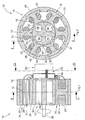
- FIGs. 1-3 are different sections or views of an electric motor 10, as shown, for example, in motor vehicles for driving Auxiliary units are used.
- the electric motor 10 becomes electronic commutated, i.e. the pole windings are controlled by a corresponding and Driver electronics controlled "contactless".
- the electric motor 10 has an inner rotor 12 and an outer stator 14.
- the stator 14 is formed by a one-piece stator base body 16 which essentially of six radial pole legs 18 and each inside adjoining pole shoes 20. Each pole leg 18 has one an electromagnetic coil-forming winding 21-26, all of one single winding wire 28 are wound.
- the stator base body 16 is made of ferromagnetic sheets formed.
- the rotor 12 has four pole shoes 30, which are at an angle of 90 ° are arranged to each other.
- the rotor pole shoes 30 form the axially outer ones Heads of the four rotor arms 36.
- the rotor arms 36 converge centrally in one Rotor shaft 38.
- the rotor body consists of a rare earth containing Material, for example made of NdFeB.
- Each stator pole piece 20 is connected to the two via a shorting bar 32 each adjacent stator pole shoes 20 connected so that the entire Stator body 16 is integrally formed.
- the one from the stator pole pieces 20 formed inner circumference is cylindrical and gap-free. Even at high Rotor speeds are thereby the wind deviation losses and Noise emissions kept low.
- the stator pole shoes form an inner ring in the area of the shorting bars 32 has a rounded axial groove 34.
- the axial groove 34 can also have a V-shaped cross section or a rectangular cross section. Due to the short-circuit bars 32, all stator pole legs 18 and stator pole shoes are 20 rigidly and integrally connected.
- On the stator body 16 is a one-piece yoke ring 40 on the outside ferromagnetic material attached.
- the yoke ring 40 has on its Inner circumference on six axial recesses 42, in the corresponding T-shaped shaped head pieces 44 of the pole legs 18 are inserted.
- the recesses and head pieces can also be semi-cylindrical.
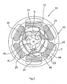
- an electrically non-conductive insulating washer 46 attached, as shown in particular in Fig. 3.
- a star point plate 48 made of electrically conductive material is attached.
- the Star point plate 48 forms a central star point for windings 21-26, to which one end of each winding 21-26 is connected.
- the star point plate 48 has a Central body 52, which lies in a transverse plane and of which three contact pins 54 protrude axially.
- the contact pins 54 have two functions. For one thing inserted into the plastic insulating washer, whereby the star point plate 48 attached to the insulating washer 46 and fixed. On the other hand, everyone points Contact pin 54 on a contact tab 56, in which the bypassed Winding wire 28 is hooked and optionally soldered or welded. to has better anchoring of the star point plate 48 in the insulating washer 46 each contact pin 54 laterally locking teeth 58 through which a fall out or Pulling out the contact pins 54 from the insulating washer 46 is prevented.
- three further contact tabs R, S, T are on the insulating disk 46 arranged with which the other ends of the windings 21-26 each are connected in pairs.
- the winding sequence and contacting is shown in Fig. 4.
- the two opposite windings 21, 24, 22, 25, 23, 26 are each parallel switched and form a pair of windings.
- the two ends of one Pair of windings 21, 24, 22, 25, 23, 26 are each with the star point plate 48 connected.
- the bridge between the two windings of a pair of windings 21, 24; 22, 25; 23, 26 is connected to one of the three contact lugs R, S, T.
- An electronic control device is in the vicinity of the star point plate 48 50 is provided, which has three electrical lines with the contact lugs R, S, T connected is.
- the control device 50 contains control electronics and Driver blocks and is used for electrical commutation of the windings 21-26.
- the short-circuit bars 32 Due to the stator geometry with the stator pole legs accessible from the outside 18, which are held together on the inside by the short-circuit bars 32, will greatly simplify and save time for winding the Windings achieved, which is particularly true for small electric motors Rotor diameter and large number of turns applies.
- Through the short-circuit bars 32 are especially the case with electric motors with high power density Cogging torques reduced, so that the resultant Vibration and noise emissions reduced. Another The cogging torque can be reduced by sloping the groove.
- the automatic winding of the stator windings 21-26 is selected by the Winding sequence and the parallel connection of two windings greatly simplified or made possible. Interconnection errors can practically be ruled out become.
Landscapes
- Engineering & Computer Science (AREA)
- Power Engineering (AREA)
- Iron Core Of Rotating Electric Machines (AREA)
- Insulation, Fastening Of Motor, Generator Windings (AREA)
- Windings For Motors And Generators (AREA)
Abstract
Description
- Herstellen des einstückigen Stator-Grundkörpers mit den Stator-Polschenkeln und den Stator-Polschuhen,
- Wickeln der Statorwicklungen auf den Stator-Polschenkeln von radial außen in einem Zug mit einem einzigen Wicklungsdraht und
- Aufsetzen eines separaten Rückschlussringes außenseitig auf die Stator-Polschenkel.
- Fig. 1
- einen Längsschnitt des erfindungsgemäßen Elektromotors,
- Fig. 2
- einen Querschnitt des erfindungsgemäßen Elektromotors der Fig. 1,
- Fig. 3
- eine Draufsicht auf eine der beiden Stirnseiten des Elektromotors der Fig. 1,
- Fig. 4
- eine Darstellung der Wickelreihenfolge des insgesamt sechs Wicklungen aufweisenden Elektromotors der Fig. 1,
- Fig. 5
- eine Seitenansicht eines Sternpunktbleches des Elektromotors der Fig. 1 und
- Fig. 6
- eine Draufsicht auf das Sternpunktblech der Fig. 5.
Claims (10)
- Elektromotor mit Innenrotor (12) und Außenstator (14) mit Statorwicklungen (21-26), wobei
der Rotor (12) mehrere permanentmagnetische Polschuhe (30) aufweist,
der Stator (14) mehrere jeweils eine Wicklung (21-26) tragende Stator-Polschenkel (18) aufweist, die radial innen den Rotor-Polschuhen (30) zugewandte Stator-Polschuhe (20) aufweisen,
die Stator-Polschuhe (20) über einen Kurzschlusssteg (32) mit den benachbarten Stator-Polschuhen (20) verbunden sind, so dass alle Stator-Polschenkel (18) und -Polschuhe (20) einstückig miteinander ausgebildet sind, und
die Stator-Polschenkel (18) außenseitig alleine durch einen separaten aufgesetzten Rückschlussring (40) miteinander verbunden sind, wobei die Wicklungen (21-26) bei entferntem Rückschlussring (40) von radial außen gewickelt wurden,
dadurch gekennzeichnet, dass
alle Wicklungen (21-26) des Stators (14) mit einem einzigen ununterbrochenen Wicklungsdraht (28) gewickelt sind. - Elektromotor nach Anspruch 1, dadurch gekennzeichnet, dass zwei parallelgeschaltete Wicklungen eines Wicklungspaars (21,24;22,25;23,26) direkt miteinander verbunden und die Wicklungspaare (21,24;22,25;23,26) seriell miteinander verbunden sind.
- Elektromotor nach Anspruch 1 oder 2, dadurch gekennzeichnet, dass der Stator 6-polig ist und die Wickelfolge 1 - 4 - 2 - 5 - 3 - 6 aufweist.
- Elektromotor nach Anspruch 2 oder 3, dadurch gekennzeichnet, dass die Verbindungen zwischen den Wicklungspaaren (21,24;22,25;23,26) einen gemeinsamen Sternpunkt bilden.
- Elektromotor nach Anspruch 4, dadurch gekennzeichnet, dass der Sternpunkt von einem einstückigen Sternpunktblech (48) gebildet wird.
- Elektromotor nach Anspruch 5, dadurch gekennzeichnet, dass der Zentralkörper (52) des Sternpunktbleches (48) in einer Querebene liegt und Kontaktstifte (54) axial davon abstehen.
- Elektromotor nach einem der Ansprüche 1-6, dadurch gekennzeichnet, dass der kleinste Querschnitt der Kurzschlussstege (32) derart klein gewählt ist, dass maximal 20 % des von einer Wicklung (21-26) erzeugten magnetischen Flusses hierüber kurzgeschlossen wird.
- Elektromotor nach einem der Ansprüche 1-7, dadurch gekennzeichnet, dass die Stator-Polschuhe (20) einen geschlossenen Innenring bilden, der im Bereich der Kurzschlussstege (32) jeweils eine Axialnut (34) aufweist.
- Elektromotor nach einem der Ansprüche 1-8, dadurch gekennzeichnet, dass die Rotor-Polschuhe (30) aus einem Seltene Erden enthaltenden Material bestehen.
- Verfahren zum Herstellen eines Außenstators (14) nach einem der Ansprüche 1-9,
gekennzeichnet durch
die Verfahrensschritte:Herstellen eines einstückigen Stator-Grundkörpers (16) mit durch die Kurzschlussstege (32) miteinander verbundenen Stator-Polschuhen (20),Bewickeln der Stator-Polschenkel (18) mit den Stator-Wicklungen (21-26) von radial außen in einem Zug mit einem einzigen Wicklungsdraht (28) undAufsetzen des Rückschlussringes (40) außen auf die Stator-Polschenkel (18).
Applications Claiming Priority (2)
| Application Number | Priority Date | Filing Date | Title |
|---|---|---|---|
| DE10152499A DE10152499A1 (de) | 2001-10-24 | 2001-10-24 | Elektromotor |
| DE10152499 | 2001-10-24 |
Publications (3)
| Publication Number | Publication Date |
|---|---|
| EP1306960A2 true EP1306960A2 (de) | 2003-05-02 |
| EP1306960A3 EP1306960A3 (de) | 2006-05-17 |
| EP1306960B1 EP1306960B1 (de) | 2008-08-13 |
Family
ID=7703580
Family Applications (1)
| Application Number | Title | Priority Date | Filing Date |
|---|---|---|---|
| EP02023112A Expired - Lifetime EP1306960B1 (de) | 2001-10-24 | 2002-10-15 | Elektromotor |
Country Status (4)
| Country | Link |
|---|---|
| US (1) | US6784584B2 (de) |
| EP (1) | EP1306960B1 (de) |
| DE (2) | DE10152499A1 (de) |
| ES (1) | ES2311044T3 (de) |
Cited By (3)
| Publication number | Priority date | Publication date | Assignee | Title |
|---|---|---|---|---|
| WO2007012207A1 (de) * | 2005-07-28 | 2007-02-01 | Thyssenkrupp Presta Ag | Stator für ein elektromotor |
| EP2744072A3 (de) * | 2012-12-17 | 2016-08-10 | LG Innotek Co., Ltd. | Motor |
| WO2022122157A1 (en) | 2020-12-10 | 2022-06-16 | Pierburg Pump Technology Gmbh | Automotive electric auxiliary unit and method for manufacturing the same |
Families Citing this family (21)
| Publication number | Priority date | Publication date | Assignee | Title |
|---|---|---|---|---|
| US7135799B2 (en) * | 2003-03-19 | 2006-11-14 | Pacsci Motion Control, Inc. | Method for winding a stator of multi-phase motors |
| JP3711996B2 (ja) * | 2004-02-06 | 2005-11-02 | ダイキン工業株式会社 | 電動機の固定子 |
| DE102004062816A1 (de) * | 2004-12-27 | 2006-07-06 | Robert Bosch Gmbh | Elektrische Maschine, insbesondere EC-Motor und Verfahren zu seiner Herstellung |
| DE102005005953A1 (de) | 2005-02-10 | 2006-08-17 | Robert Bosch Gmbh | Bürstenlose Gleichstrommaschine sowie Rückschlussringpaket, Zahnkranzpaket und Kopfteil einer Gleichstrommaschine sowie Verfahren zur Herstellung einer bürstenlosen Gleichstrommaschine |
| EP1722464B1 (de) * | 2005-05-11 | 2019-05-08 | Brose Fahrzeugteile GmbH & Co. KG, Würzburg | Verfahren zum Bewickeln des Stators eines Elektromotors und Stator für einen Elektromotor |
| JP4650323B2 (ja) * | 2006-03-29 | 2011-03-16 | トヨタ自動車株式会社 | 回転電機の巻線構造 |
| JP2008092723A (ja) * | 2006-10-04 | 2008-04-17 | Mabuchi Motor Co Ltd | ブラシレスモータ及びその製造方法 |
| DE102007032872A1 (de) * | 2007-07-12 | 2009-01-15 | Ipgate Ag | Stator für Elektromotor |
| US8901797B2 (en) * | 2008-01-29 | 2014-12-02 | Ford Global Technologies, Llc | Brushless motor system for a vehicle fuel pump |
| US20100133945A1 (en) * | 2009-06-05 | 2010-06-03 | Remy International Inc. | Segmented stator core winding apparatus and method of winding a segmented stator core |
| US8614530B2 (en) * | 2009-12-17 | 2013-12-24 | Remy Technologies, L.L.C. | Stator core for an electric machine |
| US8716910B2 (en) * | 2011-01-21 | 2014-05-06 | Remy Technologies Llc | Stator winding connection arrangement |
| CN102377255A (zh) * | 2011-10-31 | 2012-03-14 | 许晓华 | 一种改进的电机定子 |
| GB2510382A (en) * | 2013-02-01 | 2014-08-06 | Valeo Air Man Uk Ltd | A stator assembly for an electric supercharger |
| CN103580337A (zh) * | 2013-10-25 | 2014-02-12 | 中电电机股份有限公司 | 一种两极绕线电机转子压圈结构 |
| GB201320245D0 (en) * | 2013-11-15 | 2014-01-01 | Coreteq Ltd | Very high temperature electrical winding |
| JP2016052224A (ja) * | 2014-09-02 | 2016-04-11 | アイシン精機株式会社 | ステータ、そのステータを適用した回転電機及びステータの結線方法 |
| US9819246B2 (en) * | 2015-01-13 | 2017-11-14 | Regal Beloit America, Inc. | Electrical machine and controller and methods of assembling the same |
| EP3352341B1 (de) * | 2017-01-20 | 2025-07-30 | Ovalo GmbH | Statorpaket und verfahren zum herstellen eines statorpakets |
| DE102018111572A1 (de) * | 2018-05-15 | 2019-11-21 | Seg Automotive Germany Gmbh | Verfahren zum Herstellen von Wicklungen in einem Stator einer elektrischen Maschine |
| DE102021202034A1 (de) | 2021-03-03 | 2022-09-08 | Thyssenkrupp Ag | Elektromotor für ein Kraftfahrzeug-Lenksystem und Kraftfahrzeug-Lenksystem |
Family Cites Families (14)
| Publication number | Priority date | Publication date | Assignee | Title |
|---|---|---|---|---|
| US3130336A (en) * | 1951-01-19 | 1964-04-21 | George V Morris | Unit wound generator stator |
| US4131988A (en) * | 1976-10-29 | 1979-01-02 | The Globe Tool And Engineering Company | Method of manufacturing a dynamoelectric field member |
| US4752707A (en) * | 1986-02-06 | 1988-06-21 | Morrill Wayne J | Three-phase, one-third pitch motor |
| JPH0191628A (ja) * | 1987-10-02 | 1989-04-11 | Matsushita Electric Ind Co Ltd | 固定子 |
| DE9010318U1 (de) * | 1990-07-07 | 1991-11-07 | Robert Bosch Gmbh, 70469 Stuttgart | Rückschlußzylinder für elektrische Kleinmotoren |
| JP3107177B2 (ja) * | 1992-07-27 | 2000-11-06 | 株式会社安川電機 | 電動機のステータ |
| DE19506267A1 (de) * | 1995-02-23 | 1996-08-29 | Geiger Gerhard Gmbh & Co | Lamelle für dynamoelektrische Maschinen |
| JPH11511638A (ja) * | 1995-08-18 | 1999-10-05 | インターナショナル マシナリー コーポレーション | 永久磁石ロータ交流発電機 |
| DE19652795A1 (de) * | 1996-12-18 | 1998-06-25 | Siemens Ag | Stator für elektrodynamische Maschinen und Verfahren zu deren Herstellung |
| TW380329B (en) * | 1997-04-16 | 2000-01-21 | Japan Servo | Permanent-magnet revolving electrodynamic machine with a concentrated winding stator |
| JPH11332140A (ja) * | 1998-05-08 | 1999-11-30 | Sankyo Seiki Mfg Co Ltd | 放射リブ巻線式回転電機の電機子構造 |
| DE19842948A1 (de) * | 1998-09-18 | 2000-03-30 | Siemens Ag | Elektromotor |
| JP3155534B1 (ja) * | 2000-01-20 | 2001-04-09 | 三菱電機株式会社 | 交流発電機の固定子 |
| DE19961339A1 (de) * | 1999-12-17 | 2001-07-05 | Siemens Ag | Elektrische Maschine |
-
2001
- 2001-10-24 DE DE10152499A patent/DE10152499A1/de not_active Withdrawn
-
2002
- 2002-10-15 EP EP02023112A patent/EP1306960B1/de not_active Expired - Lifetime
- 2002-10-15 DE DE50212629T patent/DE50212629D1/de not_active Expired - Lifetime
- 2002-10-15 ES ES02023112T patent/ES2311044T3/es not_active Expired - Lifetime
- 2002-10-23 US US10/278,289 patent/US6784584B2/en not_active Expired - Lifetime
Cited By (4)
| Publication number | Priority date | Publication date | Assignee | Title |
|---|---|---|---|---|
| WO2007012207A1 (de) * | 2005-07-28 | 2007-02-01 | Thyssenkrupp Presta Ag | Stator für ein elektromotor |
| US7936099B2 (en) * | 2005-07-28 | 2011-05-03 | Thyssenkrupp Presta Ag | Electric motor stator |
| EP2744072A3 (de) * | 2012-12-17 | 2016-08-10 | LG Innotek Co., Ltd. | Motor |
| WO2022122157A1 (en) | 2020-12-10 | 2022-06-16 | Pierburg Pump Technology Gmbh | Automotive electric auxiliary unit and method for manufacturing the same |
Also Published As
| Publication number | Publication date |
|---|---|
| EP1306960A3 (de) | 2006-05-17 |
| ES2311044T3 (es) | 2009-02-01 |
| DE10152499A1 (de) | 2003-05-08 |
| US6784584B2 (en) | 2004-08-31 |
| US20030102765A1 (en) | 2003-06-05 |
| DE50212629D1 (de) | 2008-09-25 |
| EP1306960B1 (de) | 2008-08-13 |
Similar Documents
| Publication | Publication Date | Title |
|---|---|---|
| EP1306960B1 (de) | Elektromotor | |
| EP1810388B1 (de) | Elektromotor | |
| EP2584672B1 (de) | Gehäuseteil für eine elektrische Maschine | |
| DE102012113095B4 (de) | Bürstenloser Motor | |
| DE102006021247B4 (de) | Elektromotor | |
| DE202007014169U1 (de) | Elektromotor | |
| EP1468481B1 (de) | Statoranordnung | |
| DE10103935A1 (de) | Statoranordnung einer elektrischen Umlaufmaschine für ein Fahrzeug | |
| DE10213743A1 (de) | Stator für Elektromotoren mit Wicklungs-Verschaltungsanordnung | |
| DE202013012682U1 (de) | Elektromotor mit einer Statoranordnung und einer Rotoranordnung | |
| DE102017127611A1 (de) | Synchron-Reluktanzmotor mit durch Permanentmagnete gesättigtem magnetischen Nebenschlusspfad | |
| DE112004001898T5 (de) | Kurzschlußteil, Kommutator und Verfahren zur Herstellung eines Kurzschlußteils | |
| WO2019215097A1 (de) | Verfahren zum herstellen einer wicklung für einen ständer einer elektrischen machine und elektrische maschine | |
| DE102020115642B3 (de) | Elektrischer Motor und Leiterplatte | |
| DE102006053973B4 (de) | Elektrischer Generator | |
| DE102021129198B3 (de) | Rotor mit verschaltbaren Spuleneinheiten, elektrische Antriebsmaschine sowie Kraftfahrzeug | |
| EP1638188A1 (de) | Motor, insbesondere für Niederspannung | |
| DE102020203945A1 (de) | Statorwicklungssystem mit serieller Spulenwicklung | |
| DE102020203944A1 (de) | Verschaltungseinheit und Verfahren zum Herstellen eines Wicklungssystems | |
| WO2010037592A1 (de) | Elektrische maschine mit einem kontaktelement zur elektrischen verbindung elektrischer bauteile | |
| EP3128650A1 (de) | Gleichstrommaschine und verfahren zur herstellung einer gleichstrommaschine | |
| DE1638569A1 (de) | Kollektorloser Gleichstrom-Kleinstmotor mit permanentmagneterregtem Laeufer | |
| WO2009083327A1 (de) | Elektrische maschine mit einem eine ständerwicklung aufweisenden ständer und zugehöriges herstellungsverfahren | |
| DE102012100666A1 (de) | Elektromotor | |
| DE3901295C1 (en) | Electrical machine having permanent-magnet excitation and charging winding |
Legal Events
| Date | Code | Title | Description |
|---|---|---|---|
| PUAI | Public reference made under article 153(3) epc to a published international application that has entered the european phase |
Free format text: ORIGINAL CODE: 0009012 |
|
| AK | Designated contracting states |
Designated state(s): AT BE BG CH CY CZ DE DK EE ES FI FR GB GR IE IT LI LU MC NL PT SE SK TR |
|
| AX | Request for extension of the european patent |
Extension state: AL LT LV MK RO SI |
|
| PUAL | Search report despatched |
Free format text: ORIGINAL CODE: 0009013 |
|
| AK | Designated contracting states |
Kind code of ref document: A3 Designated state(s): AT BE BG CH CY CZ DE DK EE ES FI FR GB GR IE IT LI LU MC NL PT SE SK TR |
|
| AX | Request for extension of the european patent |
Extension state: AL LT LV MK RO SI |
|
| 17P | Request for examination filed |
Effective date: 20060919 |
|
| AKX | Designation fees paid |
Designated state(s): DE ES FR GB IT |
|
| 17Q | First examination report despatched |
Effective date: 20070417 |
|
| GRAP | Despatch of communication of intention to grant a patent |
Free format text: ORIGINAL CODE: EPIDOSNIGR1 |
|
| GRAS | Grant fee paid |
Free format text: ORIGINAL CODE: EPIDOSNIGR3 |
|
| GRAA | (expected) grant |
Free format text: ORIGINAL CODE: 0009210 |
|
| AK | Designated contracting states |
Kind code of ref document: B1 Designated state(s): DE ES FR GB IT |
|
| REG | Reference to a national code |
Ref country code: GB Ref legal event code: FG4D Free format text: NOT ENGLISH |
|
| REF | Corresponds to: |
Ref document number: 50212629 Country of ref document: DE Date of ref document: 20080925 Kind code of ref document: P |
|
| REG | Reference to a national code |
Ref country code: ES Ref legal event code: FG2A Ref document number: 2311044 Country of ref document: ES Kind code of ref document: T3 |
|
| PLBE | No opposition filed within time limit |
Free format text: ORIGINAL CODE: 0009261 |
|
| STAA | Information on the status of an ep patent application or granted ep patent |
Free format text: STATUS: NO OPPOSITION FILED WITHIN TIME LIMIT |
|
| 26N | No opposition filed |
Effective date: 20090514 |
|
| REG | Reference to a national code |
Ref country code: FR Ref legal event code: PLFP Year of fee payment: 14 |
|
| REG | Reference to a national code |
Ref country code: FR Ref legal event code: PLFP Year of fee payment: 15 |
|
| REG | Reference to a national code |
Ref country code: FR Ref legal event code: PLFP Year of fee payment: 16 |
|
| REG | Reference to a national code |
Ref country code: FR Ref legal event code: PLFP Year of fee payment: 17 |
|
| PGFP | Annual fee paid to national office [announced via postgrant information from national office to epo] |
Ref country code: ES Payment date: 20181122 Year of fee payment: 17 Ref country code: GB Payment date: 20181025 Year of fee payment: 17 Ref country code: IT Payment date: 20181022 Year of fee payment: 17 Ref country code: FR Payment date: 20181023 Year of fee payment: 17 |
|
| GBPC | Gb: european patent ceased through non-payment of renewal fee |
Effective date: 20191015 |
|
| PG25 | Lapsed in a contracting state [announced via postgrant information from national office to epo] |
Ref country code: FR Free format text: LAPSE BECAUSE OF NON-PAYMENT OF DUE FEES Effective date: 20191031 Ref country code: IT Free format text: LAPSE BECAUSE OF NON-PAYMENT OF DUE FEES Effective date: 20191015 Ref country code: GB Free format text: LAPSE BECAUSE OF NON-PAYMENT OF DUE FEES Effective date: 20191015 |
|
| REG | Reference to a national code |
Ref country code: ES Ref legal event code: FD2A Effective date: 20210302 |
|
| PG25 | Lapsed in a contracting state [announced via postgrant information from national office to epo] |
Ref country code: ES Free format text: LAPSE BECAUSE OF NON-PAYMENT OF DUE FEES Effective date: 20191016 |
|
| PGFP | Annual fee paid to national office [announced via postgrant information from national office to epo] |
Ref country code: DE Payment date: 20211020 Year of fee payment: 20 |
|
| REG | Reference to a national code |
Ref country code: DE Ref legal event code: R071 Ref document number: 50212629 Country of ref document: DE |