EP1306575B1 - Hydraulic antivibration device - Google Patents
Hydraulic antivibration device Download PDFInfo
- Publication number
- EP1306575B1 EP1306575B1 EP02023254A EP02023254A EP1306575B1 EP 1306575 B1 EP1306575 B1 EP 1306575B1 EP 02023254 A EP02023254 A EP 02023254A EP 02023254 A EP02023254 A EP 02023254A EP 1306575 B1 EP1306575 B1 EP 1306575B1
- Authority
- EP
- European Patent Office
- Prior art keywords
- plate
- flow channel
- mount
- channel
- tab
- Prior art date
- Legal status (The legal status is an assumption and is not a legal conclusion. Google has not performed a legal analysis and makes no representation as to the accuracy of the status listed.)
- Expired - Lifetime
Links
- 239000002184 metal Substances 0.000 claims description 20
- 239000012530 fluid Substances 0.000 description 10
- 238000013016 damping Methods 0.000 description 7
- 238000010276 construction Methods 0.000 description 5
- 230000000717 retained effect Effects 0.000 description 3
- 230000015572 biosynthetic process Effects 0.000 description 2
- POIUWJQBRNEFGX-XAMSXPGMSA-N cathelicidin Chemical compound C([C@@H](C(=O)N[C@@H](CCCNC(N)=N)C(=O)N[C@@H](CCCCN)C(=O)N[C@@H](CO)C(=O)N[C@@H](CCCCN)C(=O)N[C@@H](CCC(O)=O)C(=O)N[C@@H](CCCCN)C(=O)N[C@@H]([C@@H](C)CC)C(=O)NCC(=O)N[C@@H](CCCCN)C(=O)N[C@@H](CCC(O)=O)C(=O)N[C@@H](CC=1C=CC=CC=1)C(=O)N[C@@H](CCCCN)C(=O)N[C@@H](CCCNC(N)=N)C(=O)N[C@@H]([C@@H](C)CC)C(=O)N[C@@H](C(C)C)C(=O)N[C@@H](CCC(N)=O)C(=O)N[C@@H](CCCNC(N)=N)C(=O)N[C@@H]([C@@H](C)CC)C(=O)N[C@@H](CCCCN)C(=O)N[C@@H](CC(O)=O)C(=O)N[C@@H](CC=1C=CC=CC=1)C(=O)N[C@@H](CC(C)C)C(=O)N[C@@H](CCCNC(N)=N)C(=O)N[C@@H](CC(N)=O)C(=O)N[C@@H](CC(C)C)C(=O)N[C@@H](C(C)C)C(=O)N1[C@@H](CCC1)C(=O)N[C@@H](CCCNC(N)=N)C(=O)N[C@@H]([C@@H](C)O)C(=O)N[C@@H](CCC(O)=O)C(=O)N[C@@H](CO)C(O)=O)NC(=O)[C@H](CC=1C=CC=CC=1)NC(=O)[C@H](CC(O)=O)NC(=O)CNC(=O)[C@H](CC(C)C)NC(=O)[C@@H](N)CC(C)C)C1=CC=CC=C1 POIUWJQBRNEFGX-XAMSXPGMSA-N 0.000 description 2
- 238000004891 communication Methods 0.000 description 2
- 230000000694 effects Effects 0.000 description 2
- 238000005192 partition Methods 0.000 description 2
- 238000005266 casting Methods 0.000 description 1
- 238000007796 conventional method Methods 0.000 description 1
- 238000002788 crimping Methods 0.000 description 1
- 238000003754 machining Methods 0.000 description 1
- 239000000463 material Substances 0.000 description 1
- 239000012528 membrane Substances 0.000 description 1
- 238000000034 method Methods 0.000 description 1
- 230000003014 reinforcing effect Effects 0.000 description 1
Images
Classifications
-
- F—MECHANICAL ENGINEERING; LIGHTING; HEATING; WEAPONS; BLASTING
- F16—ENGINEERING ELEMENTS AND UNITS; GENERAL MEASURES FOR PRODUCING AND MAINTAINING EFFECTIVE FUNCTIONING OF MACHINES OR INSTALLATIONS; THERMAL INSULATION IN GENERAL
- F16F—SPRINGS; SHOCK-ABSORBERS; MEANS FOR DAMPING VIBRATION
- F16F13/00—Units comprising springs of the non-fluid type as well as vibration-dampers, shock-absorbers, or fluid springs
- F16F13/04—Units comprising springs of the non-fluid type as well as vibration-dampers, shock-absorbers, or fluid springs comprising both a plastics spring and a damper, e.g. a friction damper
- F16F13/06—Units comprising springs of the non-fluid type as well as vibration-dampers, shock-absorbers, or fluid springs comprising both a plastics spring and a damper, e.g. a friction damper the damper being a fluid damper, e.g. the plastics spring not forming a part of the wall of the fluid chamber of the damper
- F16F13/08—Units comprising springs of the non-fluid type as well as vibration-dampers, shock-absorbers, or fluid springs comprising both a plastics spring and a damper, e.g. a friction damper the damper being a fluid damper, e.g. the plastics spring not forming a part of the wall of the fluid chamber of the damper the plastics spring forming at least a part of the wall of the fluid chamber of the damper
- F16F13/10—Units comprising springs of the non-fluid type as well as vibration-dampers, shock-absorbers, or fluid springs comprising both a plastics spring and a damper, e.g. a friction damper the damper being a fluid damper, e.g. the plastics spring not forming a part of the wall of the fluid chamber of the damper the plastics spring forming at least a part of the wall of the fluid chamber of the damper the wall being at least in part formed by a flexible membrane or the like
- F16F13/105—Units comprising springs of the non-fluid type as well as vibration-dampers, shock-absorbers, or fluid springs comprising both a plastics spring and a damper, e.g. a friction damper the damper being a fluid damper, e.g. the plastics spring not forming a part of the wall of the fluid chamber of the damper the plastics spring forming at least a part of the wall of the fluid chamber of the damper the wall being at least in part formed by a flexible membrane or the like characterised by features of partitions between two working chambers
Definitions
- the present invention is directed to an hydraulic antivibration device. More specifically, the present invention is directed to an improved flow channel deflector for a hydraulic engine mount.
- a typical engine mount contains two sealed chambers separated by an intermediate partition having a damping channel passing there through and providing communication between the chambers.
- the engine mount normally has one end member attached to an engine block and another end member attached to a vehicle frame, with the end members being resiliently connected to each other by an elastomeric member which permits one end member to move in response to vibrations with respect to the other.
- hydraulic fluid is pumped back and forth from one chamber to the other through the damping channel in the partition.
- the damping channel may be formed in a variety of methods. The most conventional method is with the use of a pair of thick metal plates. Within each metal plate, a partial arcuate groove is formed around the circumference of each plate and then the plates are matched so that the grooves are aligned, forming a channel. The channel opening and exit are offset from each other so that the fluid must flow at least partially through the channel to get from one chamber to the other.
- These conventional plates are formed by casting, press forming or machining thick metal into which the grooves are machined.
- EP-A-0849493 discloses an anti-vibration mount according to the preamble of claim 1.
- EP-A-0231898 describes an anti-vibration mount having a central decoupling membrane sandwiched between two metal plates wherein annular metal plates have integral tabs extending inclined into the flow channel.
- the present invention is directed to a simplified construction of the damper plate resulting in a lighter weight damper plate and easier construction of the mount.
- the present invention is a hydraulically damped anti-vibration mount.
- the mount has a rubber spring, an outer metal casing, an end cap, and a damper plate.
- the spring is encased within the outer metal casing, the outer metal casing being crimped to the end cap, and the damper plate dividing the interior of the mount into an upper and a lower chamber.
- the damper plate is formed from an upper plate and a lower plate.
- the upper and lower plates form a flow channel between the two plates which extends at least partially around the circumference of the damper plate, the flow channel permitting communication between the upper and lower chamber.
- the upper plate has an opening communicating to the upper chamber with a tab integral with the upper plate extending from the opening into the flow channel to block the channel.
- the upper plate is a flat metal plate to form the top of the flow channel.
- the lower plate has a trough extending about the circumference of the plate to form the base of the flow channel.
- the tab formed in the top plate may be generally L-shaped, extending both into the flow channel and along the flow channel.
- the tab may be fixedly secured to the base of the flow channel.
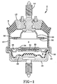
- FIG. 1 A hydraulic antivibration mount is illustrated in FIG 1. It is to be understood that the terms “upper” and “lower” are used only for the clarity of the description since the described mount may be used in a reverse orientation.
- the mount 2 has an annular rubber spring 8 set in an outer metal casing 10, encasing an inner metal portion 12 having a central mounting means 14.
- the outer metal casing 10 is crimped over the flange 16 of an end cap 18.
- a flexible diaphragm 22 Located with the end cap 18 and retained within the crimped portion 20 is a damper plate 24 dividing the interior of the mount 2 into an upper chamber A and a lower chamber B to be filled with fluid.
- a cup shaped bumper 28 attached to the inner metal portion 12 and extending axially inward into the upper chamber A.
- the bumper 28 has a radially outwardly extending flange 30 with a flexible flab 32 extending radially outwardly from the flange 30 toward the inner cavity wall 32.
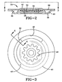
- the damper plate 24 has a disc-type decoupler 34, see also FIG. 2.
- the decoupler 34 may be provided with reinforcing 35 to vary the response characteristics of the decoupler 34.
- the edges of the decoupler 34 are crimped by the internal circumferential edge of the thin metal plates 36, 38. Both the top and bottom plates 36, 38 are circular shaped with central openings.
- the bottom plate 38 has a trough 40 that extends around the circumference of the plate.
- the exact configuration, or cross-sectional area, of the trough 40 is selected, in connection with the viscosity of the damping fluid, to achieve a desired damping effect for the intended application of the mount 2.
- At one end of the trough 40 is an opening 42 for the fluid to flow out of the channel and into chamber B, see FIG. 3.
- the opening 42 extends along an arcuate portion of the trough 40.
- the plate 38 has a raised internal portion at the inner edge for gripping the decoupler 34.
- the top plate 36 also has a raised internal portion 44 at the inner edge 46 for gripping the decoupler 34; however, the remainer of the plate 36 is generally flat, covering the trough 40 to complete the formation of the channel 26.
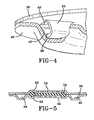
- an opening 48 Located along an arcuate portion of the circumference of the plate 36 is an opening 48 to the flow channel 26.
- a tab 50 illustrated in FIG 4, that diverts the flow of fluid into the channel 26.
- the tab 50 extends from the surface of the plate 36 into the channel 26.
- the tab 50 is formed by material removed to form the opening 48 or is separately welded to the plate 36.
- the edges of the tab 50 correspond in configuration to the cross-sectional shape of the channel 26.
- the base of the tab 50 is fixedly secured to the base of the channel to prevent the tab 50 from movement due to fluid pressure.
- the tab 50 acts to divert the fluid flow into and around the channel 26.
- the fluid must flow into the channel opening 48 and out of the channel exit 42.
- the arcuate length of the opening 48 and the exit 42 are selected to achieve a desired damping characteristic. While the exit 42 is shown to be directly adjacent to the tab 50, the arcuate channel length may be effectively reduced by distancing the exit 42 from the tab 50. Such a placement may create some backflow in the channel 26, and this should be taken into consideration when determining the damping effects of the mount 2.
- the edges 46 forming the central openings are illustrated as scalloped edges 46.
- the central opening edges 46 are crimped together to retain the decoupler 34. After crimping, the scalloped edges 46 of the plates 36, 38 may or may not be aligned; alternatively, the inner edges 46 may have a non-scalloped configuration.
- FIG. 5 shows an alternative construction of the damper plate 24.
- the damper plate is again formed of two plates 36, 38.
- the plates 36, 38 are disc-shaped with raised central portions 52 and a decoupler 34 retained within the central portions.
- the plates 36, 38 are provided with a series of orifices 54.
- the channel 26, and any variations in the channel formation, is as already described.
Landscapes
- Engineering & Computer Science (AREA)
- General Engineering & Computer Science (AREA)
- Mechanical Engineering (AREA)
- Combined Devices Of Dampers And Springs (AREA)
Applications Claiming Priority (2)
| Application Number | Priority Date | Filing Date | Title |
|---|---|---|---|
| US475 | 2001-10-24 | ||
| US10/000,475 US6612554B1 (en) | 2001-10-24 | 2001-10-24 | Hydraulic antivibration device |
Publications (3)
| Publication Number | Publication Date |
|---|---|
| EP1306575A2 EP1306575A2 (en) | 2003-05-02 |
| EP1306575A3 EP1306575A3 (en) | 2004-08-25 |
| EP1306575B1 true EP1306575B1 (en) | 2007-08-01 |
Family
ID=21691671
Family Applications (1)
| Application Number | Title | Priority Date | Filing Date |
|---|---|---|---|
| EP02023254A Expired - Lifetime EP1306575B1 (en) | 2001-10-24 | 2002-10-17 | Hydraulic antivibration device |
Country Status (6)
| Country | Link |
|---|---|
| US (1) | US6612554B1 (enExample) |
| EP (1) | EP1306575B1 (enExample) |
| JP (1) | JP2003139190A (enExample) |
| CA (1) | CA2407030A1 (enExample) |
| DE (1) | DE60221478T2 (enExample) |
| MX (1) | MXPA02010110A (enExample) |
Families Citing this family (22)
| Publication number | Priority date | Publication date | Assignee | Title |
|---|---|---|---|---|
| US7416173B2 (en) * | 2004-05-24 | 2008-08-26 | Tokai Rubber Industries, Ltd. | Pneumatically switchable type fluid-filled engine mount |
| KR100622500B1 (ko) * | 2004-12-17 | 2006-09-19 | 현대자동차주식회사 | 엔진 마운팅 인슐레이터 |
| JP2007092972A (ja) * | 2005-09-30 | 2007-04-12 | Tokai Rubber Ind Ltd | 流体封入式防振装置 |
| KR100722311B1 (ko) * | 2005-11-05 | 2007-05-28 | 평화산업주식회사 | 유체봉입식 마운트장치 |
| US7347437B1 (en) * | 2006-09-28 | 2008-03-25 | Gm Global Technology Operations, Inc. | Damper assembly |
| WO2011087019A1 (ja) * | 2010-01-12 | 2011-07-21 | 株式会社ブリヂストン | 防振装置 |
| WO2012085766A1 (en) | 2010-12-24 | 2012-06-28 | Teklas Kaucuk Sanayi Ve Ticaret A.S. | A hydraulic mount |
| CN103847489A (zh) * | 2012-11-29 | 2014-06-11 | 重庆长安汽车股份有限公司 | 一种发动机液压悬置的限位结构 |
| CN103291830B (zh) * | 2013-05-10 | 2015-12-09 | 安徽江淮汽车股份有限公司 | 一种发动机液压悬置 |
| US10190651B2 (en) * | 2016-06-16 | 2019-01-29 | Beijingwest Industries Co., Ltd. | Multi-stage damping assembly |
| CN107143596B (zh) * | 2016-06-16 | 2019-07-26 | 北京京西重工有限公司 | 用于多级阻尼的组件 |
| KR102509951B1 (ko) * | 2016-12-15 | 2023-03-13 | 현대자동차주식회사 | 소음 저감을 위한 멤브레인을 가지는 엔진 마운트 |
| DE102017112168B4 (de) * | 2017-06-01 | 2021-04-29 | Vibracoustic Gmbh | Trennvorrichtung zum Trennen einer Arbeitskammer und einer Ausgleichskammer eines hydraulisch dämpfenden Lagers sowie ein hydraulisch dämpfendes Lager |
| DE102018102130A1 (de) * | 2018-01-31 | 2019-08-01 | Vibracoustic Gmbh | Hydraulisch dämpfendes Lager |
| CN112074672B (zh) * | 2018-05-10 | 2022-05-17 | 株式会社普利司通 | 隔振装置 |
| USD897374S1 (en) * | 2018-11-03 | 2020-09-29 | North American Aerospace Corporation | Engine mount |
| JP7350629B2 (ja) | 2019-11-07 | 2023-09-26 | 株式会社プロスパイラ | 防振装置 |
| WO2021090946A1 (ja) | 2019-11-07 | 2021-05-14 | 株式会社ブリヂストン | 防振装置 |
| WO2021090949A1 (ja) | 2019-11-07 | 2021-05-14 | 株式会社ブリヂストン | 防振装置 |
| WO2021090886A1 (ja) | 2019-11-07 | 2021-05-14 | 株式会社ブリヂストン | 防振装置 |
| JP7348433B2 (ja) * | 2020-10-26 | 2023-09-21 | 山下ゴム株式会社 | 開閉体用液封ダンパ |
| CN113915287A (zh) * | 2021-10-25 | 2022-01-11 | 建新赵氏科技有限公司 | 一种液压悬置解耦隔振装置 |
Family Cites Families (26)
| Publication number | Priority date | Publication date | Assignee | Title |
|---|---|---|---|---|
| FR2467724A1 (fr) | 1979-10-22 | 1981-04-30 | Peugeot | Cale elastique, notamment pour la suspension d'un moteur de vehicule |
| JPS57191127A (en) | 1981-05-18 | 1982-11-24 | Nissan Motor Co Ltd | Engine mount filled with fluid |
| DE3244296A1 (de) | 1982-11-30 | 1984-05-30 | Metzeler Kautschuk GmbH, 8000 München | Zweikammer-motorlager mit hydraulischer daempfung |
| GB8313111D0 (en) | 1983-05-12 | 1983-06-15 | Avon Ind Polymers | Hydraulically damped mounting |
| DE3347274C2 (de) | 1983-12-28 | 1987-02-26 | Lemförder Metallwaren AG, 2844 Lemförde | Hydraulischer Schwingungsdämpfer für elastische Stützlager in Kraftfahrzeugen |
| JPS60184737A (ja) * | 1984-02-21 | 1985-09-20 | Honda Motor Co Ltd | 流体入りマウント |
| DE3421135A1 (de) | 1984-06-07 | 1985-12-12 | Audi AG, 8070 Ingolstadt | Hydraulisches motorlager |
| DE3522482A1 (de) | 1985-06-22 | 1987-01-15 | Freudenberg Carl Fa | Hydraulisch daempfendes motorlager |
| DE3526607A1 (de) | 1985-07-25 | 1987-01-29 | Continental Gummi Werke Ag | Hydraulisch gedaempftes elastisches lager |
| US4709907A (en) | 1986-01-30 | 1987-12-01 | Thorn Richard P | Quiet fluid filled vibration isolator |
| EP0231898B1 (de) * | 1986-02-03 | 1991-06-12 | Lord Corporation | Hydraulisch dämpfendes Lager |
| IT1197531B (it) * | 1986-10-31 | 1988-11-30 | Pirelli Accessori Ind | Dispositivo smorzatore |
| US4836513A (en) | 1988-03-16 | 1989-06-06 | The Goodyear Tire & Rubber Company | Hydraulically damped anti-vibration mount with a flexible flap as a dynamic rate inhibitor |
| JPH0538260Y2 (enExample) | 1988-06-06 | 1993-09-28 | ||
| US4925162A (en) | 1988-06-17 | 1990-05-15 | Bridgestone Corporation | Vibration isolating devices |
| JP2510903B2 (ja) * | 1991-06-03 | 1996-06-26 | 東海ゴム工業株式会社 | 流体封入式マウント装置およびその製造方法 |
| DE4216185C2 (de) * | 1992-05-15 | 1994-12-08 | Boge Gmbh | Elastisches Gummilager |
| JP2861779B2 (ja) | 1993-12-20 | 1999-02-24 | 豊田合成株式会社 | 液封入防振装置 |
| US6032935A (en) * | 1996-06-06 | 2000-03-07 | Toyo Tire & Rubber Co., Ltd. | Liquid enclosing type vibration isolating mount |
| JPH109334A (ja) * | 1996-06-21 | 1998-01-13 | Tokai Rubber Ind Ltd | 液体封入式防振装置及びその取付金具の製造方法 |
| US5786022A (en) * | 1996-10-31 | 1998-07-28 | Ethicon, Inc. | Coating mixture for surgical articles |
| DE19652501C1 (de) * | 1996-12-17 | 1998-07-16 | Contitech Formteile Gmbh | Selbstschaltendes Hydrauliklager mit akustischer Abkopplung |
| DE19902493C2 (de) * | 1999-01-22 | 2001-02-01 | Freudenberg Carl Fa | Umschaltbares Zweikammer-Stützlager mit hydraulischer Dämpfung |
| DE19902494C2 (de) * | 1999-01-22 | 2002-10-31 | Freudenberg Carl Kg | Umschaltbares Zweikammerstützlager mit hydraulischer Dämpfung |
| US6435487B1 (en) * | 1999-07-12 | 2002-08-20 | Toyo Tire & Rubber Co., Ltd. | Liquid sealed type vibration isolator |
| JP3489500B2 (ja) * | 1999-08-10 | 2004-01-19 | 東海ゴム工業株式会社 | 防振装置 |
-
2001
- 2001-10-24 US US10/000,475 patent/US6612554B1/en not_active Expired - Fee Related
-
2002
- 2002-10-09 CA CA002407030A patent/CA2407030A1/en not_active Abandoned
- 2002-10-14 MX MXPA02010110A patent/MXPA02010110A/es active IP Right Grant
- 2002-10-17 EP EP02023254A patent/EP1306575B1/en not_active Expired - Lifetime
- 2002-10-17 DE DE60221478T patent/DE60221478T2/de not_active Expired - Fee Related
- 2002-10-18 JP JP2002304756A patent/JP2003139190A/ja not_active Withdrawn
Also Published As
| Publication number | Publication date |
|---|---|
| DE60221478T2 (de) | 2008-04-24 |
| JP2003139190A (ja) | 2003-05-14 |
| US6612554B1 (en) | 2003-09-02 |
| DE60221478D1 (de) | 2007-09-13 |
| EP1306575A2 (en) | 2003-05-02 |
| CA2407030A1 (en) | 2003-04-24 |
| EP1306575A3 (en) | 2004-08-25 |
| MXPA02010110A (es) | 2003-04-29 |
Similar Documents
| Publication | Publication Date | Title |
|---|---|---|
| EP1306575B1 (en) | Hydraulic antivibration device | |
| EP0042761B1 (en) | Rubber vibration isolator | |
| EP0147242B1 (en) | Vibration isolating devices | |
| EP2047137B1 (en) | Very high damping body mount, subframe mount or engine mount with bolt-through construction | |
| US4159091A (en) | Damper device, in particular for the suspension of an engine | |
| EP0357245B1 (en) | Hydraulically damped mount | |
| US4595183A (en) | Vibration isolating device | |
| US4756514A (en) | Fluid-filled resilient bushing having excellent axial vibration damping characteristic | |
| JP2657951B2 (ja) | 二室エンジン支持体 | |
| US4676489A (en) | Two chamber engine mount with hydraulic damping | |
| EP0133588B1 (en) | Vibration isolating device and system | |
| US8177201B2 (en) | Very high damping mount with bolt-through construction | |
| EP0342680A2 (en) | Hydraulically damped mounting device | |
| US20040212133A1 (en) | Hydraulic antivibration support | |
| JPH0229897B2 (enExample) | ||
| EP0293726B1 (en) | Support device for damping radial vibrations | |
| JP7348433B2 (ja) | 開閉体用液封ダンパ | |
| JP3590904B2 (ja) | 防振装置 | |
| JPH0236813B2 (enExample) | ||
| JPH0417291B2 (enExample) | ||
| JP7348434B2 (ja) | 開閉体用液封ダンパ | |
| JP3838280B2 (ja) | 液体封入式エンジンマウント | |
| EP0326665B1 (en) | Vibration damping device | |
| JPH0828623A (ja) | 流体封入式マウント装置およびその製造方法 | |
| JP3454571B2 (ja) | 制御式液体封入マウント |
Legal Events
| Date | Code | Title | Description |
|---|---|---|---|
| PUAI | Public reference made under article 153(3) epc to a published international application that has entered the european phase |
Free format text: ORIGINAL CODE: 0009012 |
|
| AK | Designated contracting states |
Designated state(s): AT BE BG CH CY CZ DE DK EE ES FI FR GB GR IE IT LI LU MC NL PT SE SK TR |
|
| AX | Request for extension of the european patent |
Extension state: AL LT LV MK RO SI |
|
| PUAL | Search report despatched |
Free format text: ORIGINAL CODE: 0009013 |
|
| AK | Designated contracting states |
Kind code of ref document: A3 Designated state(s): AT BE BG CH CY CZ DE DK EE ES FI FR GB GR IE IT LI LU MC NL PT SE SK TR |
|
| AX | Request for extension of the european patent |
Extension state: AL LT LV MK RO SI |
|
| 17P | Request for examination filed |
Effective date: 20050225 |
|
| AKX | Designation fees paid |
Designated state(s): DE FR GB IT |
|
| 17Q | First examination report despatched |
Effective date: 20050427 |
|
| RBV | Designated contracting states (corrected) |
Designated state(s): DE FR GB IT |
|
| GRAP | Despatch of communication of intention to grant a patent |
Free format text: ORIGINAL CODE: EPIDOSNIGR1 |
|
| GRAS | Grant fee paid |
Free format text: ORIGINAL CODE: EPIDOSNIGR3 |
|
| GRAA | (expected) grant |
Free format text: ORIGINAL CODE: 0009210 |
|
| AK | Designated contracting states |
Kind code of ref document: B1 Designated state(s): DE FR GB IT |
|
| REG | Reference to a national code |
Ref country code: GB Ref legal event code: FG4D |
|
| REF | Corresponds to: |
Ref document number: 60221478 Country of ref document: DE Date of ref document: 20070913 Kind code of ref document: P |
|
| ET | Fr: translation filed | ||
| PGFP | Annual fee paid to national office [announced via postgrant information from national office to epo] |
Ref country code: IT Payment date: 20071027 Year of fee payment: 6 |
|
| PGFP | Annual fee paid to national office [announced via postgrant information from national office to epo] |
Ref country code: GB Payment date: 20071019 Year of fee payment: 6 Ref country code: FR Payment date: 20071030 Year of fee payment: 6 |
|
| PGFP | Annual fee paid to national office [announced via postgrant information from national office to epo] |
Ref country code: DE Payment date: 20071221 Year of fee payment: 6 |
|
| PLBE | No opposition filed within time limit |
Free format text: ORIGINAL CODE: 0009261 |
|
| STAA | Information on the status of an ep patent application or granted ep patent |
Free format text: STATUS: NO OPPOSITION FILED WITHIN TIME LIMIT |
|
| 26N | No opposition filed |
Effective date: 20080506 |
|
| GBPC | Gb: european patent ceased through non-payment of renewal fee |
Effective date: 20081017 |
|
| REG | Reference to a national code |
Ref country code: FR Ref legal event code: ST Effective date: 20090630 |
|
| PG25 | Lapsed in a contracting state [announced via postgrant information from national office to epo] |
Ref country code: IT Free format text: LAPSE BECAUSE OF NON-PAYMENT OF DUE FEES Effective date: 20081017 Ref country code: DE Free format text: LAPSE BECAUSE OF NON-PAYMENT OF DUE FEES Effective date: 20090501 |
|
| PG25 | Lapsed in a contracting state [announced via postgrant information from national office to epo] |
Ref country code: FR Free format text: LAPSE BECAUSE OF NON-PAYMENT OF DUE FEES Effective date: 20081031 |
|
| PG25 | Lapsed in a contracting state [announced via postgrant information from national office to epo] |
Ref country code: GB Free format text: LAPSE BECAUSE OF NON-PAYMENT OF DUE FEES Effective date: 20081017 |