EP1306252B1 - Sonnenblende für Fahrzeuge - Google Patents
Sonnenblende für Fahrzeuge Download PDFInfo
- Publication number
- EP1306252B1 EP1306252B1 EP20020023266 EP02023266A EP1306252B1 EP 1306252 B1 EP1306252 B1 EP 1306252B1 EP 20020023266 EP20020023266 EP 20020023266 EP 02023266 A EP02023266 A EP 02023266A EP 1306252 B1 EP1306252 B1 EP 1306252B1
- Authority
- EP
- European Patent Office
- Prior art keywords
- slide
- edges
- sun visor
- mirror
- spring elements
- Prior art date
- Legal status (The legal status is an assumption and is not a legal conclusion. Google has not performed a legal analysis and makes no representation as to the accuracy of the status listed.)
- Expired - Lifetime
Links
- 238000006073 displacement reaction Methods 0.000 claims description 9
- 239000000463 material Substances 0.000 claims description 3
- 230000003014 reinforcing effect Effects 0.000 description 8
- 230000002093 peripheral effect Effects 0.000 description 3
- 230000015572 biosynthetic process Effects 0.000 description 2
- 230000006641 stabilisation Effects 0.000 description 2
- 238000011105 stabilization Methods 0.000 description 2
- 238000002347 injection Methods 0.000 description 1
- 239000007924 injection Substances 0.000 description 1
- 238000001746 injection moulding Methods 0.000 description 1
- 230000013011 mating Effects 0.000 description 1
- 239000002184 metal Substances 0.000 description 1
- 239000000243 solution Substances 0.000 description 1
- 230000008646 thermal stress Effects 0.000 description 1
Images

Classifications
-
- B—PERFORMING OPERATIONS; TRANSPORTING
- B60—VEHICLES IN GENERAL
- B60J—WINDOWS, WINDSCREENS, NON-FIXED ROOFS, DOORS, OR SIMILAR DEVICES FOR VEHICLES; REMOVABLE EXTERNAL PROTECTIVE COVERINGS SPECIALLY ADAPTED FOR VEHICLES
- B60J3/00—Antiglare equipment associated with windows or windscreens; Sun visors for vehicles
- B60J3/02—Antiglare equipment associated with windows or windscreens; Sun visors for vehicles adjustable in position
- B60J3/0204—Sun visors
- B60J3/0278—Sun visors structure of the body
- B60J3/0282—Sun visors structure of the body specially adapted for a courtesy mirror
Definitions
- the invention relates to a sun visor for vehicles, with a mirror which is recessed in a recess of the sun visor body, and a manually operable mirror cover in the form of a plastic slide, which has on the side facing away from the mirror a handle bar and with its in The displacement direction extending edges in each case engages a groove-like guide and has at one of its two extending in the direction of displacement edges spring elements.
- the slider In the currently used sun visors with a mirror cover in the form of a slider, the slider is guided with its running in the direction of displacement edges in U-shaped guides.
- the U-shaped guides cause a three-sided surface contact in the upper and lower guide region of the slide, which does not allow a controllable and manageable sliding of the slider in the guides.
- the parts, ie the slide and the guides are produced with a dimensionally very large tolerance game to the slider even at to operate larger temperature fluctuations.
- this relatively large tolerance game often leads to complaints, as a result, the slide can move unintentionally and even - which is even less desirable - can develop into a rather unpleasant noise source by causing rattling noises.
- each projection is formed by an outwardly arched, at the bottom of the U-shaped guide supporting bar formed on their both ends formed integrally with the slider, the rest is separated by a slot from the slider.
- the slider can rattle in the U-shaped guides, since the opening width of the U-shaped guide is larger to substantially larger than the thickness of the engaging therein slide edges. If the opening width is reduced, there is a risk that the slide can no longer be actuated in the event of material expansion due to thermal stress.
- the present invention is based on the object, a sun visor of the type mentioned with an improved, In particular, rattle-free guide for the Spiegelabdeckschieber available.
- the invention provides that the extending in the direction of displacement edges of the slide as well as the guide receiving the edges provided groove-like guides V- or vice versa V-shaped and that the spring elements having the edge of the slide is provided with recesses each having a recess bottom and a pocket-like recess extending from the recess bottom, each of which is made of harnessgleitmmem plastic material and engaging in the pocket-like plug-in webs, each one extending between the connecting webs spring clip and a formed in one of the groove-like guides engaging V- or vice versa V-shaped headboard.
- the inventive measures a significant quality improvement is achieved in a simple and cost-effective manner.
- the slider has due to the V-shaped mesh with his guides only two sliding surfaces on top and bottom, so that he no longer wobble perpendicular to the slider level and therefore can not rattle.
- a wobbling or rattling in the slider plane counteract the spring elements with which the slide is equipped.
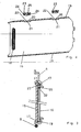
- FIG. 1 shows a complete sun visor 1, comprising a covered sun visor body 2 with an abutment pin 3, a mounted mounting unit 4 and a mirror system 5 integrated in the sun visor body 2.
- FIG. 2 shows a reinforcing insert 6, which is essentially made of plastic injection molding and has a U-shaped wire stabilization 8, which is fixed at clip-in points 9, in order to avoid torsions in the outer region 7.
- abutment pin 3 is reinforced with a wire hanger 11 by plug-in assembly to meet the crash requirements.
- the reinforcing insert 6 has an axle receiving portion 12 for the axis 13 of the Anschraubaggregats 4 and a detent spring 14 for the sliding / cogging torque.
- the mirror 15 is preassembled with the slider 16 corresponding to section AA as the Anschraubaggregat 4.
- the upper and lower V-like guide 17 for the slider 16 extends almost over the entire length of the reinforcing insert. 6
- the slider 16 is a plastic injection molded part with approximately rectangular shape with a handle bar 18 and the formation of an upper and lower V-like or V-shaped peripheral edge 19, wherein the upper peripheral edge 19 has two recesses 20 in the bottom 21 each with a pocket-like Recess 22 are provided, which serve for receiving the two sliding / spring elements 23, which are hosed from good sliding plastic.
- the two sliding / spring elements 23 have at the top (head part 26) also a V- or roof-like formation 19 as on the slide 16, each have two plug-in webs 24 for mounting in the pocket-like recess 22 and a respective spring clip 25th It is understood that the slide / spring elements 23 protrude with relieved spring clip 25, the upper peripheral edge 19 of the slider 16 and thus engage in the mounted state under the force of the spring clip 25 standing in the upper guide 17.
- the upper and under V-like edge 19 on the slider 16 and the upper and lower V-like guide 17 of the reinforcing insert 6 cause by their combination, the dimensional adjustment and the two sliding / spring elements 23, for an optimal sliding / sliding action and second, a rattle-free and play-free mating due to the special shape of the sliding and guiding zones.
Landscapes
- Engineering & Computer Science (AREA)
- Mechanical Engineering (AREA)
- Mirrors, Picture Frames, Photograph Stands, And Related Fastening Devices (AREA)
Description
- Die Erfindung bezieht sich auf eine Sonnenblende für Fahrzeuge, mit einem Spiegel, der vertieft in einer Aussparung des Sonnenblendenkörpers liegt, und einer manuell betätigbaren Spiegelabdeckung in Form eines aus Kunststoff bestehenden Schiebers, der auf der dem Spiegel abgekehrten Seite eine Griffleiste aufweist und mit seinen in der Verschieberichtung verlaufenden Rändern in je eine nutartige Führung eingreift und an einem seiner beiden in der Verschieberichtung verlaufenden Ränder Federelemente aufweist.
- Bei den zur Zeit gebräuchlichen Sonnenblenden mit einer Spiegelabdeckung in Form eines Schiebers wird der Schieber mit seinen in der Verschieberichtung verlaufenden Rändern in U-förmigen Führungen geführt. Die U-förmigen Führungen bewirken eine dreiseitige Flächenberührung im oberen und unteren Führungsbereich des Schiebers, die eine kontrollierbare und beherrschbare Gleitung des Schiebers in den Führungen nicht zuläßt. In der Regel werden die Teile, d.h. der Schieber und die Führungen mit einem maßlich sehr großen Toleranzspiel produziert, um den Schieber auch noch bei größeren Temperaturschwankungen betätigen zu können. Dieses relativ große Toleranzspiel führt aber häufig zu Reklamationen, da sich hierdurch der Schieber ungewollt verschieben kann und auch - was noch weniger erwünscht ist - zu einer recht unangenehmen Geräuschquelle entwickeln kann, indem er Klappergeräusche verursacht.
- Um ein verbessertes Gleiten des Schiebers in den U-förmigen Führungen zu erreichen, wurden schon an den in der Verschieberichtung verlaufenden Rändern des Schiebers Metallfedern angeordnet, die aber nicht dazu führen konnten, die unangenehmen Klappergeräusche abzustellen, siehe z.B. US-A-4,948,240. Bei einer Sonnenblende der eingangs genannten Art, weist der Schieber an wenigstens einem seiner beiden in der Verschieberichtung verlaufenden Ränder federnde Vorsprünge auf, wobei jeder Vorsprung durch eine nach außen gewölbte, sich am Boden der U-förmigen Führung abstützenden Leiste gebildet ist, die an ihren beiden Enden einstückig mit dem Schieber ausgebildet, im übrigen durch einen Schlitz vom Schieber getrennt ist. Aber auch bei dieser bekannten Ausführungsform kann der Schieber in den U-förmigen Führungen klappern, da die Öffnungsweite der U-förmigen Führung größer bis wesentlich größer als die Dicke der darin eingreifenden Schieberränder ist. Bei einer Verkleinerung der Öffnungsweite besteht die Gefahr, dass sich der Schieber bei Materialausdehnung infolge thermischer Belastung nicht mehr betätigen lässt.
- Der vorliegenden Erfindung liegt hiernach die Aufgabe zugrunde, eine Sonnenblende der eingangs genannten Art mit einer verbesserten, insbesondere auch klapperfreien Führung für den Spiegelabdeckschieber zur Verfügung zu stellen.
- Zur Lösung dieser Aufgabe ist erfindungsgemäß vorgesehen, dass die in der Verschieberrichtung verlaufenden Ränder des Schiebers ebenso wie die zur Führungsaufnahme der Ränder vorgesehenen nutartigen Führungen V- bzw. umgekehrt V-förmig ausgebildet sind und dass der die Federelemente aufweisende Rand des Schiebers mit Ausnehmungen versehen ist, die jeweils einen Ausnehmungsboden und eine vom Ausnehmungsboden ausgehende taschenartige Vertiefung aufweisen, die jeweils zur Aufnahme eines Federelements bestimmt ist, wobei die Federelemente jeweils aus hochgleitfähigem Kunststoffmaterial gefertigt und mit in die taschenartige Vertiefung eingreifenden Steckstegen, jeweils einem sich zwischen den Steckstegen erstreckenden Federbügel und einen in eine der nutartigen Führungen eingreifenden V- bzw. umgekehrt V-förmig gestalteten Kopfteil ausgebildet sind.
- Durch die erfindungsgemäßen Maßnahmen wird in einfacher und kostengünstiger Weise eine wesentliche Qualitätsverbesserung erreicht. Der Schieber weist aufgrund des V-förmigen Ineinandergreifens mit seinen Führungen nur noch zwei Gleitflächen oberseitig und unterseitig auf, so dass er senkrecht zur Schieberebene nicht mehr wackeln und daher auch nicht mehr klappern kann. Einem Wackeln oder Klappern in Schieberebene wirken die Federelemente, mit denen der Schieber ausgerüstet ist, entgegen.
- Ein Ausführungsbeispiel der Erfindung wird im folgenden anhand der Zeichnung näher erläutert, und es zeigen:
- Fig. 1
- eine Sonnenblende in Ansicht,
- Fig. 2
- eine Verstärkungseinlage für die Sonnenblende nach Fig. 1,
- Fig. 3
- einen Schnitt etwa folgend der Linie A-A in Fig. 2 und
- Fig. 4
- eine Einzelheit der Sonnenblende.
- Fig. 1 stellt eine komplette Sonnenblende 1 dar, bestehend aus einem umhüllten Sonnenblendenkörper 2 mit einem Gegenlagerstift 3, einem montierten Anschraubaggregat 4 und einem im Sonnenblendenkörper 2 integriertem Spiegelsystem 5.
- Fig. 2 zeigt eine im wesentlich aus Kunststoffspritzguß erstellte Verstärkungseinlage 6, die zur Vermeidung von Verwindungen im äußeren Bereich 7 eine U-förmige Drahtstabilisierung 8 aufweist, die an Einklipsstellen 9 festgelegt ist. Im Gegenlagerbereich 10 ist der an der Verstärkungseinlage 6 angespritzte Gegenlagerstift 3 mit einem Drahtbügel 11 durch Steckmontage verstärkt, um die Crashforderungen zu erfüllen. Die Verstärkungseinlage 6 weist einen Achsaufnahmebereich 12 für die Achse 13 des Anschraubaggregats 4 auf sowie eine Rastfeder 14 für das Gleit-/Rastmoment. Da die Verstärkungseinlage 6 vornehmlich für ein Blendenkörperhalbschalensystem vorgesehen ist, ist der Spiegel 15 mit dem Schieber 16 entsprechend Schnitt A-A ebenso vormontiert wie das Anschraubaggregat 4. Die obere und untere V-artige Führung 17 für den Schieber 16 erstreckt sich nahezu über die gesamte Länge der Verstärkungseinlage 6.
- Der Schieber 16 ist ein Kunststoffspritzteil mit etwa rechteckiger Form mit einer Griffleiste 18 und der Ausbildung einer oberen und unteren V-artigen oder umgekehrt V-förmigen Randkante 19, wobei die obere Randkante 19 zwei Ausnehmungen 20 aufweist, die im Boden 21 jeweils mit einer taschenartigen Vertiefung 22 versehen sind, welche zur Aufnahme der beiden Gleit-/Federelemente 23, die aus gut gleitfähigem Kunststoff abgespritzt sind, dienen.
- Die beiden Gleit-/Federelemente 23 weisen an der Oberseite (Kopfteil 26) ebenso eine V- bzw. dachartige Ausbildung 19 auf wie die am Schieber 16, haben jeweils zwei Steckstege 24 für die Montage in die taschenartige Vertiefung 22 und jeweils einen Federbügel 25. Es verstehe sich, dass die Gleit-/Federelemente 23 bei entlastetem Federbügel 25 die obere Randkante 19 des Schiebers 16 überragen und somit im montierten Zustand unter der Kraft der Federbügel 25 stehend in die obere Führung 17 eingreifen.
- Die obere und unter V-artige Randkante 19 am Schieber 16 und die obere und untere V-artige Führung 17 der Verstärkungseinlage 6 bewirken durch ihre Kombination, der maßlichen Abstimmung und den beiden Gleit-/Federelementen 23, zum einen eine optimale Schiebe-/Gleitwirkung und zum anderen eine klapper- und spielfreie Paarung aufgrund der besonderen Formgebung der Gleit- und Führungszonen.
-
- 1
- Sonnenblende
- 2
- Sonnenblendenkörper
- 3
- Gegenlagerstift
- 4
- Anschraubaggregat
- 5
- Spiegelsystem
- 6
- Verstärkungseinlage
- 7
- äußerer Bereich
- 8
- Drahtstabilisierung
- 9
- Einklipsstellen
- 10
- Gegenlagerbereich
- 11
- Drahtbügel
- 12
- Achsaufnahmebereich
- 13
- Achse
- 14
- Rastfeder
- 15
- Spiegel
- 16
- Schieber
- 17
- Führung
- 18
- Griffleiste
- 19
- Randkante
- 20
- Ausnehmung
- 21
- Boden
- 22
- Vertiefung
- 23
- Gleit-/Federelement
- 24
- Stecksteg
- 25
- Federbügel
- 26
- Kopfteil
Claims (1)
- Sonnenblende für Fahrzeuge mit einem Spiegel (15), der vertieft in einer Aussparung des Sonnenblendenkörpers (2) liegt, und einer manuell betätigbaren Spiegelabdeckung in Form eines aus Kunststoff bestehenden Schiebers (16), der auf der dem Spiegel (15) abgekehrten Seite eine Griffleiste (18) aufweist und mit seinen in der Verschieberichtung verlaufenden Rändern (19) in je eine nutartige Führung (17) eingreift und an einem seiner beiden in der Verschieberichtung verlaufenden Ränder (19) Federelemente (23) aufweist, dadurch gekennzeichnet, dass die in der Verschieberichtung verlaufenden Ränder (19) des Schiebers (16) ebenso wie die zur Führungsaufnahme der Ränder (19) vorgesehenen nutartigen Führung (17) V- bzw. umgekehrt V-förmig ausgebildet sind und dass der die Federelemente 23 aufweisende Rand (19) des Schiebers (16) mit Ausnehmungen (20) versehen ist, die jeweils einem Ausnehmungsboden (21) und eine vom Ausnehmungsboden (21) ausgehende taschenartige Vertiefung (22) aufweisen, die jeweils zur Aufnahme eines Federelements (23) bestimmt ist, wobei die Federelemente (23) jeweils aus hochgleitfähigem Kunststoffmaterial gefertigt und mit in die taschenartige Vertiefung (22) eingreifenden Steckstegen (24), jeweils einem sich zwischen den Steckstegen (24) erstreckenden Federbügel (25) und einen in eine der nutartigen Führungen (17) eingreifenden V- bzw. umgekehrt V-förmig gestalteten Kopfteil (26) ausgebildet sind.
Applications Claiming Priority (2)
| Application Number | Priority Date | Filing Date | Title |
|---|---|---|---|
| DE10153154 | 2001-10-27 | ||
| DE2001153154 DE10153154B4 (de) | 2001-10-27 | 2001-10-27 | Sonnenblende für Fahrzeuge |
Publications (2)
| Publication Number | Publication Date |
|---|---|
| EP1306252A1 EP1306252A1 (de) | 2003-05-02 |
| EP1306252B1 true EP1306252B1 (de) | 2006-08-09 |
Family
ID=7703976
Family Applications (1)
| Application Number | Title | Priority Date | Filing Date |
|---|---|---|---|
| EP20020023266 Expired - Lifetime EP1306252B1 (de) | 2001-10-27 | 2002-10-17 | Sonnenblende für Fahrzeuge |
Country Status (3)
| Country | Link |
|---|---|
| EP (1) | EP1306252B1 (de) |
| DE (2) | DE10164887B4 (de) |
| ES (1) | ES2271169T3 (de) |
Families Citing this family (2)
| Publication number | Priority date | Publication date | Assignee | Title |
|---|---|---|---|---|
| ES2542503T3 (es) * | 2007-02-13 | 2015-08-06 | Grupo Antolín-Ingeniería, S.A. | Conjunto de parasol, parasol y método para montarlo |
| DE502008000304D1 (de) | 2008-03-25 | 2010-02-25 | Smr Patents Sarl | Sonnenblende mit Plastikspiegel |
Family Cites Families (9)
| Publication number | Priority date | Publication date | Assignee | Title |
|---|---|---|---|---|
| DE3324169A1 (de) * | 1983-07-05 | 1985-01-24 | Wolfgang 7140 Ludwigsburg Zipperle | Sonnenblende fuer kraftfahrzeuge |
| DE8419962U1 (de) * | 1984-07-04 | 1985-11-07 | Adam Opel AG, 6090 Rüsselsheim | Sonnenblende für Kraftfahrzeuge |
| US4653798A (en) * | 1985-12-23 | 1987-03-31 | White Jay E | Sun visor mirror |
| US4711483A (en) * | 1986-01-21 | 1987-12-08 | Irvin Industries, Inc. | Motor vehicle visor with removable mirror assembly |
| EP0331779B1 (de) * | 1988-03-09 | 1991-04-17 | Michael Zipperle | Sonnenblende für Kraftfahrzeuge |
| GB2218059B (en) * | 1988-04-30 | 1991-09-11 | Austin Rover Group | A sun visor |
| US5205639A (en) * | 1990-08-31 | 1993-04-27 | White Jay E | Vehicular sun visor assembly |
| US5813717A (en) * | 1996-05-15 | 1998-09-29 | Automotive Industries, Inc. | Cable operated dual synchronous opening mirror doors for sun visors |
| DE19737346A1 (de) * | 1997-08-27 | 1999-03-04 | Happich Gmbh Gebr | Sonnenblende für Fahrzeuge |
-
2001
- 2001-10-27 DE DE10164887A patent/DE10164887B4/de not_active Expired - Fee Related
-
2002
- 2002-10-17 DE DE50207771T patent/DE50207771D1/de not_active Expired - Lifetime
- 2002-10-17 ES ES02023266T patent/ES2271169T3/es not_active Expired - Lifetime
- 2002-10-17 EP EP20020023266 patent/EP1306252B1/de not_active Expired - Lifetime
Also Published As
| Publication number | Publication date |
|---|---|
| DE10164887B4 (de) | 2006-04-27 |
| DE50207771D1 (de) | 2006-09-21 |
| EP1306252A1 (de) | 2003-05-02 |
| ES2271169T3 (es) | 2007-04-16 |
Similar Documents
| Publication | Publication Date | Title |
|---|---|---|
| EP2015971B1 (de) | Wischblatt | |
| EP1765645B1 (de) | Vorrichtung zum befestigen eines regensensors an einem träger | |
| EP0380013B1 (de) | Vorrichtung zur Befestigung eines Dachhimmels einer Schiebedach- oder Schiebehebedachkonstruktion | |
| EP1375273B1 (de) | Scheibenwischvorrichtung | |
| DE2718445C2 (de) | Aufsteckgläser für eine Brille | |
| EP3710317B1 (de) | Wischblatt | |
| EP2658756A1 (de) | Wischvorrichtung, insbesondere kraftfahrzeugscheibenwischvorrichtung | |
| EP1306252B1 (de) | Sonnenblende für Fahrzeuge | |
| DE102004041665B4 (de) | Gurtführung sowie Gurtaufroller mit einer solchen Gurtführung | |
| EP1662155B1 (de) | Kunststoffanbauteil für ein Kraftfahrzeug | |
| DE19952823B4 (de) | Laubschutzvorrichtung an einer/für eine Dachrinnenanordnung | |
| DE10153154B4 (de) | Sonnenblende für Fahrzeuge | |
| EP2105332B1 (de) | Sonnenblende mit Plastikspiegel | |
| DE10306733B4 (de) | Vorrichtung zur Arretierung, Körper und Anordnung | |
| EP1394331B1 (de) | Aufhängeteil | |
| DE3501915C2 (de) | ||
| EP1375275B1 (de) | Getriebe-Antriebseinheit mit Rastelement | |
| EP0264570B1 (de) | Potentiometer | |
| DE3916625A1 (de) | Sonnenblende fuer fahrzeuge | |
| DE8013676U1 (de) | Sonnenblende fuer kraftfahrzeuge | |
| DE102005002312B4 (de) | Mitnehmer für Seilzug-Fensterheber | |
| DE10148969B4 (de) | Stellantrieb für ein Fahrzeug | |
| DE102007033594A1 (de) | Wischerblatt für einen Scheibenwischer | |
| WO2013152920A1 (de) | Wischblattvorrichtung | |
| DE10161235A1 (de) | Sonnenblende für Fahrzeuge |
Legal Events
| Date | Code | Title | Description |
|---|---|---|---|
| PUAI | Public reference made under article 153(3) epc to a published international application that has entered the european phase |
Free format text: ORIGINAL CODE: 0009012 |
|
| AK | Designated contracting states |
Designated state(s): AT BE BG CH CY CZ DE DK EE ES FI FR GB GR IE IT LI LU MC NL PT SE SK TR |
|
| AX | Request for extension of the european patent |
Extension state: AL LT LV MK RO SI |
|
| 17P | Request for examination filed |
Effective date: 20031103 |
|
| AKX | Designation fees paid |
Designated state(s): DE ES FR GB IT SK |
|
| RBV | Designated contracting states (corrected) |
Designated state(s): DE ES FR GB IT |
|
| GRAP | Despatch of communication of intention to grant a patent |
Free format text: ORIGINAL CODE: EPIDOSNIGR1 |
|
| RBV | Designated contracting states (corrected) |
Designated state(s): DE ES FR GB IT SK |
|
| GRAS | Grant fee paid |
Free format text: ORIGINAL CODE: EPIDOSNIGR3 |
|
| GRAA | (expected) grant |
Free format text: ORIGINAL CODE: 0009210 |
|
| AK | Designated contracting states |
Kind code of ref document: B1 Designated state(s): DE ES FR GB IT SK |
|
| PG25 | Lapsed in a contracting state [announced via postgrant information from national office to epo] |
Ref country code: IT Free format text: LAPSE BECAUSE OF FAILURE TO SUBMIT A TRANSLATION OF THE DESCRIPTION OR TO PAY THE FEE WITHIN THE PRESCRIBED TIME-LIMIT;WARNING: LAPSES OF ITALIAN PATENTS WITH EFFECTIVE DATE BEFORE 2007 MAY HAVE OCCURRED AT ANY TIME BEFORE 2007. THE CORRECT EFFECTIVE DATE MAY BE DIFFERENT FROM THE ONE RECORDED. Effective date: 20060809 Ref country code: SK Free format text: LAPSE BECAUSE OF FAILURE TO SUBMIT A TRANSLATION OF THE DESCRIPTION OR TO PAY THE FEE WITHIN THE PRESCRIBED TIME-LIMIT Effective date: 20060809 |
|
| REG | Reference to a national code |
Ref country code: GB Ref legal event code: FG4D Free format text: NOT ENGLISH |
|
| REF | Corresponds to: |
Ref document number: 50207771 Country of ref document: DE Date of ref document: 20060921 Kind code of ref document: P |
|
| GBT | Gb: translation of ep patent filed (gb section 77(6)(a)/1977) |
Effective date: 20061109 |
|
| ET | Fr: translation filed | ||
| REG | Reference to a national code |
Ref country code: ES Ref legal event code: FG2A Ref document number: 2271169 Country of ref document: ES Kind code of ref document: T3 |
|
| PLBE | No opposition filed within time limit |
Free format text: ORIGINAL CODE: 0009261 |
|
| STAA | Information on the status of an ep patent application or granted ep patent |
Free format text: STATUS: NO OPPOSITION FILED WITHIN TIME LIMIT |
|
| 26N | No opposition filed |
Effective date: 20070510 |
|
| PGFP | Annual fee paid to national office [announced via postgrant information from national office to epo] |
Ref country code: GB Payment date: 20080919 Year of fee payment: 7 |
|
| PGFP | Annual fee paid to national office [announced via postgrant information from national office to epo] |
Ref country code: ES Payment date: 20081008 Year of fee payment: 7 |
|
| PG25 | Lapsed in a contracting state [announced via postgrant information from national office to epo] |
Ref country code: GB Free format text: LAPSE BECAUSE OF NON-PAYMENT OF DUE FEES Effective date: 20091017 |
|
| REG | Reference to a national code |
Ref country code: ES Ref legal event code: FD2A Effective date: 20110331 |
|
| PG25 | Lapsed in a contracting state [announced via postgrant information from national office to epo] |
Ref country code: ES Free format text: LAPSE BECAUSE OF NON-PAYMENT OF DUE FEES Effective date: 20110321 |
|
| PG25 | Lapsed in a contracting state [announced via postgrant information from national office to epo] |
Ref country code: ES Free format text: LAPSE BECAUSE OF NON-PAYMENT OF DUE FEES Effective date: 20091018 |
|
| REG | Reference to a national code |
Ref country code: FR Ref legal event code: PLFP Year of fee payment: 13 |
|
| PGFP | Annual fee paid to national office [announced via postgrant information from national office to epo] |
Ref country code: DE Payment date: 20150310 Year of fee payment: 13 Ref country code: IT Payment date: 20150327 Year of fee payment: 13 |
|
| PGFP | Annual fee paid to national office [announced via postgrant information from national office to epo] |
Ref country code: FR Payment date: 20150310 Year of fee payment: 13 |
|
| REG | Reference to a national code |
Ref country code: DE Ref legal event code: R119 Ref document number: 50207771 Country of ref document: DE |
|
| PG25 | Lapsed in a contracting state [announced via postgrant information from national office to epo] |
Ref country code: IT Free format text: LAPSE BECAUSE OF NON-PAYMENT OF DUE FEES Effective date: 20151017 Ref country code: DE Free format text: LAPSE BECAUSE OF NON-PAYMENT OF DUE FEES Effective date: 20160503 |
|
| REG | Reference to a national code |
Ref country code: FR Ref legal event code: ST Effective date: 20160630 |
|
| PG25 | Lapsed in a contracting state [announced via postgrant information from national office to epo] |
Ref country code: FR Free format text: LAPSE BECAUSE OF NON-PAYMENT OF DUE FEES Effective date: 20151102 |