EP1306156A1 - Echangeur thermique - Google Patents
Echangeur thermique Download PDFInfo
- Publication number
- EP1306156A1 EP1306156A1 EP00987763A EP00987763A EP1306156A1 EP 1306156 A1 EP1306156 A1 EP 1306156A1 EP 00987763 A EP00987763 A EP 00987763A EP 00987763 A EP00987763 A EP 00987763A EP 1306156 A1 EP1306156 A1 EP 1306156A1
- Authority
- EP
- European Patent Office
- Prior art keywords
- tubes
- heat exchanger
- brazing material
- recessed portions
- outer surfaces
- Prior art date
- Legal status (The legal status is an assumption and is not a legal conclusion. Google has not performed a legal analysis and makes no representation as to the accuracy of the status listed.)
- Withdrawn
Links
Images


Classifications
-
- B—PERFORMING OPERATIONS; TRANSPORTING
- B23—MACHINE TOOLS; METAL-WORKING NOT OTHERWISE PROVIDED FOR
- B23K—SOLDERING OR UNSOLDERING; WELDING; CLADDING OR PLATING BY SOLDERING OR WELDING; CUTTING BY APPLYING HEAT LOCALLY, e.g. FLAME CUTTING; WORKING BY LASER BEAM
- B23K1/00—Soldering, e.g. brazing, or unsoldering
- B23K1/0008—Soldering, e.g. brazing, or unsoldering specially adapted for particular articles or work
- B23K1/0012—Brazing heat exchangers
-
- F—MECHANICAL ENGINEERING; LIGHTING; HEATING; WEAPONS; BLASTING
- F28—HEAT EXCHANGE IN GENERAL
- F28D—HEAT-EXCHANGE APPARATUS, NOT PROVIDED FOR IN ANOTHER SUBCLASS, IN WHICH THE HEAT-EXCHANGE MEDIA DO NOT COME INTO DIRECT CONTACT
- F28D1/00—Heat-exchange apparatus having stationary conduit assemblies for one heat-exchange medium only, the media being in contact with different sides of the conduit wall, in which the other heat-exchange medium is a large body of fluid, e.g. domestic or motor car radiators
- F28D1/02—Heat-exchange apparatus having stationary conduit assemblies for one heat-exchange medium only, the media being in contact with different sides of the conduit wall, in which the other heat-exchange medium is a large body of fluid, e.g. domestic or motor car radiators with heat-exchange conduits immersed in the body of fluid
- F28D1/03—Heat-exchange apparatus having stationary conduit assemblies for one heat-exchange medium only, the media being in contact with different sides of the conduit wall, in which the other heat-exchange medium is a large body of fluid, e.g. domestic or motor car radiators with heat-exchange conduits immersed in the body of fluid with plate-like or laminated conduits
- F28D1/0391—Heat-exchange apparatus having stationary conduit assemblies for one heat-exchange medium only, the media being in contact with different sides of the conduit wall, in which the other heat-exchange medium is a large body of fluid, e.g. domestic or motor car radiators with heat-exchange conduits immersed in the body of fluid with plate-like or laminated conduits a single plate being bent to form one or more conduits
-
- F—MECHANICAL ENGINEERING; LIGHTING; HEATING; WEAPONS; BLASTING
- F28—HEAT EXCHANGE IN GENERAL
- F28F—DETAILS OF HEAT-EXCHANGE AND HEAT-TRANSFER APPARATUS, OF GENERAL APPLICATION
- F28F9/00—Casings; Header boxes; Auxiliary supports for elements; Auxiliary members within casings
- F28F9/02—Header boxes; End plates
- F28F9/04—Arrangements for sealing elements into header boxes or end plates
- F28F9/16—Arrangements for sealing elements into header boxes or end plates by permanent joints, e.g. by rolling
- F28F9/18—Arrangements for sealing elements into header boxes or end plates by permanent joints, e.g. by rolling by welding
Definitions
- the present invention relates to a heat exchanger which is provided with tubes for flowing a medium and exchanges heat of the medium with heat conducted to the tubes.
- a heat exchanger such as a condenser, an evaporator, a radiator, a heater core or the like mounted on automobiles is provided with tubes for flowing a medium, fins fitted to the tubes and tanks which are connected to the tube ends and configured to perform the heat exchange of the medium with heat conducted to the tubes and the fins.
- this type of heat exchanger is produced by assembling the tubes, fins and tanks which are made of aluminum or an aluminum alloy and heating the assembly in a furnace to be brazed into one body.
- a brazing material and flux necessary for the brazing are previously applied to necessary portions of the respective members before heating.
- tubes for the heat exchanger those produced by shaping a plate-shaped material are known. And, these tubes are provided with beads which are shaped by bending a material, and the beads serve to improve a heat-exchange property and a pressure resistance of the tubes.
- this heat exchanger has a sacrifice layer disposed on the outer surfaces of the tubes, so that the corrosion resistance of the tubes can be improved.
- the sacrifice layer which is formed of an Al-Zn based alloy is disposed on the core material of the tubes made of an Al-Mn based alloy, and electric potential of the tube core material becomes high with respect to the sacrifice layer.
- the corrosion resistance of the tubes is improved by a sacrificial anode effect.
- the present invention is a heat exchanger which is provided with tubes for flowing a medium and tanks to which ends of the tubes are connected, performs heat exchange of the medium by heat conducted to the tubes, has the tubes and the tanks assembled to form a heat exchanger core, and has the heat exchanger core brazed into one body, wherein the tubes are formed by shaping a plate-shaped material, have beads which are formed by bending the material, and have a sacrifice layer disposed on the outer surfaces of the tubes; the heat exchanger core, excluding at least the tubes, is provided with a brazing material for filling recessed portions on the outer surfaces of the tubes which are formed when the beads are formed; and the recessed portions on the outer surfaces of the tubes are filled with the brazing material which melts from the heat exchanger core at the time of integral brazing.
- the corrosion resistance of the tubes is efficiently secured.
- the recessed portions on the outer surfaces of the tubes tend to gather dust and water and become a cause of promoting corrosion of the tubes.
- the present invention provides the sacrifice layer on the outer surfaces of the tubes and recessed portions are filled with the brazing material, which melts from the heat exchanger core, into the recessed portions.
- the corrosion resistance of the tubes is improved securely.
- the brazing material for filling the recessed portions is provided on the tubes, the production cost becomes very high. Therefore, the brazing material for filling the recessed portions is disposed on the heat exchanger core other than the tubes to save the cost.
- the brazing material to be used may be in a form such as clad on the tanks, disposed on the fins, a replaced brazing material disposed on the heat exchanger core, or the like.
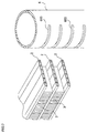
- a heat exchanger of this embodiment is a condenser of a refrigerating cycle for an in-car air conditioner mounted on automobiles, and has a heat exchanger core 1 configured by alternately stacking a plurality of tubes 2 and a plurality of fins 3 and connecting both ends of the tubes 2 to a pair of tanks 4.
- the tanks 4 of this embodiment are cylindrical members which are provided with an inlet joint 401 and an outlet joint 402 for connecting an external pipe and holes 403 into which the ends of the tubes 2 are inserted for connection, and have their inside portioned at a prescribed width.
- a medium is taken-in through the inlet joint 401, passing through the tubes 2 while heat exchanging with heat conducted to the tubes 2 and the fins 3 and discharged through the outlet joint 402.
- side plates 5 which are reinforcing members, are respectively disposed on the top and bottom of a layer of the tubes 2 and the fins 3. Both ends of the side plates 5 are supported by the tanks 4.
- the tubes 2, the fins 3, the tanks 4 and the side plates 5 are assembled by a jig, and heated in a furnace to be brazed into one body.
- a brazing material and flux are previously disposed at necessary portions of these members.
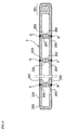
- the tubes 2 of this embodiment have a flat shape formed by rolling a plate-shaped material 200 made of an aluminum alloy so to have a joined portion 201 which is formed by connecting the ends in a breadth direction of the material 200 and a plurality of beads 202 which are formed by bending the material 200 inwardly, and the joined portion 201, the tops of the beads 202 and the inner opposed portions are brazed. And, a sacrifice layer 210 is disposed on the surface of the material 200 which will become the outer surfaces of the tubes 2.
- the beads 202 improve the heat-exchange property and pressure resistance of the tubes 2, and the sacrifice layer 210 improves the corrosion resistance of the tubes 2.
- the beads 202 may be formed to braze the opposed tops mutually as shown in Fig. 4.
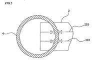
- a brazing material R fills the recessed portions 203 on the outer surfaces of the tubes 2 formed according to the beads 202.
- the brazing material R to fill the recessed portions 203 melts from the fins 3 and the tanks 4 at the time of brazing and enters into the recessed portions 203 as shown in Fig. 5 and Fig. 6.
- the brazing material is clad to or disposed on the fins 3, and the tubes 2 have the tops of the fins 3 brazed by brazing and the brazing material R melting from the fins 3 enters into the recessed portions 203.
- the replaced brazing material may be disposed between the tubes 2 and the fins 3 or between the tubes 2 and the tanks 4.
- the entry of dust and water into the recessed portions 203 can be prevented by filling the recessed portions 203 with the brazing material R, and the corrosion resistance of the tubes 2 can be improved.
- the tubes 2 can be reinforced by the brazing material R, and the pressure resistance and strength of the tubes 2 can also be improved.
- the brazing material R may partly fill around the tops of the fins 3, around the holes 403 of the tanks 4, or the like.
- the replaced brazing material may be disposed as the brazing material on the outer surface of the tubes 2 to fill the recessed portions 203 with the brazing material. Specifically, it may be configured to fill the recessed portions 203 with the replaced brazing material disposed on the tubes 2 in additon to the brazing material melting from the fins 3 and the tanks 4.
- the tubes are formed by shaping the plate-shaped material and have the beads which are formed by bending the material, the sacrifice layer is disposed on the outer surfaces, and the brazing material which melts from the fins and the tanks at the time of brazing fills the recessed portions on the outer surfaces of the tubes which are formed according to the beads.
- the corrosion resistance of the tubes can be secured efficiently.
- the recessed portions on the outer surface of the tubes tend to gather dust and water and become a cause of promoting the corrosion of the tubes.
- the present invention disposes the sacrifice layer on the outer surfaces of the tubes and the brazing material, which melts from the tanks and the fins, enters into and fills the recessed portions, so that the corrosion resistance of the tubes can be improved without fail.
- the tubes of this embodiment are formed by shaping the plate-shaped material and have the beads which are formed by bending the material, and the sacrifice layer is disposed on the outer surfaces of the tubes.
- the heat exchanger is configured by disposing the replaced brazing material on the tubes at the time of brazing and the brazing material of the replaced brazing material fills the recessed portions on the outer surfaces of the tubes which are formed according to the beads. This configuration secures the corrosion resistance of the tubes efficiently.
- the corrosion resistance of the tubes can be improved without fail by filling the recessed portions with the brazing material of the replaced brazing material disposed on the tubes.
- the tubes 2 and the plurality of fins 3 are alternately stacked, and both ends of the tubes are respectively connected to the pair of tanks 4 to configure the heat exchanger core 1.
- the present invention is not limited to it and can also be applied to, for example, a heat exchanger core not using fins and a heat exchanger core of another embodiment.
- the present invention is a heat exchanger which can have the corrosion resistance of the tubes secured efficiently and can be suitably used as a heat exchanger for a condenser, an evaporator, a radiator, a heater core and the like mounted on automobiles.
Landscapes
- Engineering & Computer Science (AREA)
- Mechanical Engineering (AREA)
- Physics & Mathematics (AREA)
- Thermal Sciences (AREA)
- General Engineering & Computer Science (AREA)
- Heat-Exchange Devices With Radiators And Conduit Assemblies (AREA)
- Details Of Heat-Exchange And Heat-Transfer (AREA)
Applications Claiming Priority (3)
| Application Number | Priority Date | Filing Date | Title |
|---|---|---|---|
| JP2000001854 | 2000-01-07 | ||
| JP2000001854A JP3998880B2 (ja) | 2000-01-07 | 2000-01-07 | 熱交換器 |
| PCT/JP2000/009345 WO2001049443A1 (fr) | 2000-01-07 | 2000-12-27 | Echangeur thermique |
Publications (2)
| Publication Number | Publication Date |
|---|---|
| EP1306156A1 true EP1306156A1 (fr) | 2003-05-02 |
| EP1306156A4 EP1306156A4 (fr) | 2009-11-11 |
Family
ID=18531035
Family Applications (1)
| Application Number | Title | Priority Date | Filing Date |
|---|---|---|---|
| EP00987763A Withdrawn EP1306156A4 (fr) | 2000-01-07 | 2000-12-27 | Echangeur thermique |
Country Status (4)
| Country | Link |
|---|---|
| US (1) | US20020179297A1 (fr) |
| EP (1) | EP1306156A4 (fr) |
| JP (1) | JP3998880B2 (fr) |
| WO (1) | WO2001049443A1 (fr) |
Cited By (13)
| Publication number | Priority date | Publication date | Assignee | Title |
|---|---|---|---|---|
| DE102006002789A1 (de) * | 2006-01-20 | 2007-07-26 | Modine Manufacturing Co., Racine | Flachrohr, Wärmetauscher und Herstellungsverfahren für Wärmetauscher |
| DE102006016711A1 (de) * | 2006-04-08 | 2007-10-11 | Modine Manufacturing Co., Racine | Flachrohr für Wärmetauscher |
| US7921559B2 (en) | 2006-01-19 | 2011-04-12 | Modine Manufacturing Company | Flat tube, flat tube heat exchanger, and method of manufacturing same |
| US8091621B2 (en) | 2006-01-19 | 2012-01-10 | Modine Manufacturing Company | Flat tube, flat tube heat exchanger, and method of manufacturing same |
| US8191258B2 (en) | 2006-01-19 | 2012-06-05 | Modine Manufacturing Company | Flat tube, flat tube heat exchanger, and method of manufacturing same |
| US8281489B2 (en) | 2006-01-19 | 2012-10-09 | Modine Manufacturing Company | Flat tube, flat tube heat exchanger, and method of manufacturing same |
| US8434227B2 (en) | 2006-01-19 | 2013-05-07 | Modine Manufacturing Company | Method of forming heat exchanger tubes |
| US8438728B2 (en) | 2006-01-19 | 2013-05-14 | Modine Manufacturing Company | Flat tube, flat tube heat exchanger, and method of manufacturing same |
| US8683690B2 (en) | 2006-01-19 | 2014-04-01 | Modine Manufacturing Company | Flat tube, flat tube heat exchanger, and method of manufacturing same |
| US8726508B2 (en) | 2006-01-19 | 2014-05-20 | Modine Manufacturing Company | Flat tube, flat tube heat exchanger, and method of manufacturing same |
| US9038267B2 (en) | 2010-06-10 | 2015-05-26 | Modine Manufacturing Company | Method of separating heat exchanger tubes and an apparatus for same |
| CN105021078A (zh) * | 2014-05-02 | 2015-11-04 | 泰安鼎鑫冷却器有限公司 | 一种双向折叠六重管壁加强型散热管 |
| DE102006035210B4 (de) * | 2006-07-29 | 2016-10-06 | Modine Manufacturing Co. | Flaches Wärmetauscherrohr und Herstellungsverfahren |
Families Citing this family (7)
| Publication number | Priority date | Publication date | Assignee | Title |
|---|---|---|---|---|
| US6530514B2 (en) * | 2001-06-28 | 2003-03-11 | Outokumpu Oyj | Method of manufacturing heat transfer tubes |
| DE102007004993A1 (de) * | 2007-02-01 | 2008-08-07 | Modine Manufacturing Co., Racine | Herstellungsverfahren für Flachrohre und Walzenstraße |
| CN105004209A (zh) * | 2014-04-25 | 2015-10-28 | 泰安鼎鑫冷却器有限公司 | 一种t型加强筋高强度散热管 |
| JP6632868B2 (ja) * | 2015-11-05 | 2020-01-22 | 日軽熱交株式会社 | アルミニウム製熱交換器 |
| EP3399267A1 (fr) * | 2017-05-02 | 2018-11-07 | Valeo Systemes Thermiques | Tube plat pour échangeur de chaleur et échangeur de chaleur |
| WO2018202630A1 (fr) * | 2017-05-02 | 2018-11-08 | Valeo Systemes Thermiques | Tube plat destiné à un échangeur de chaleur et échangeur de chaleur |
| JP7086278B2 (ja) * | 2019-04-15 | 2022-06-17 | 三菱電機株式会社 | 熱交換器及び空気調和機 |
Citations (3)
| Publication number | Priority date | Publication date | Assignee | Title |
|---|---|---|---|---|
| US5054549A (en) * | 1989-03-06 | 1991-10-08 | Sanden Corporation | Heat exchanger |
| JPH04143598A (ja) * | 1990-10-04 | 1992-05-18 | Nippondenso Co Ltd | 熱交換器 |
| FR2765817A1 (fr) * | 1997-07-11 | 1999-01-15 | Valeo Thermique Moteur Sa | Tube plie pour un echangeur de chaleur, notamment de vehicule automobile |
Family Cites Families (5)
| Publication number | Priority date | Publication date | Assignee | Title |
|---|---|---|---|---|
| JP3093847B2 (ja) * | 1991-12-18 | 2000-10-03 | 昭和アルミニウム株式会社 | 熱交換器用チューブの製造方法 |
| GB2303089B (en) * | 1995-07-13 | 1998-04-15 | T & N Technology Ltd | Forming heat exchangers |
| JP3799671B2 (ja) * | 1996-08-07 | 2006-07-19 | 株式会社デンソー | 熱交換器、熱交換器用チューブ及び熱交換器の製造方法 |
| JP2000227293A (ja) * | 1999-02-05 | 2000-08-15 | Zexel Corp | 熱交換器及びその製造方法 |
| JP2000271735A (ja) * | 1999-03-30 | 2000-10-03 | Bosch Automotive Systems Corp | 熱交換器のろう付け用フラックス混合物の塗布方法及び熱交換器 |
-
2000
- 2000-01-07 JP JP2000001854A patent/JP3998880B2/ja not_active Expired - Fee Related
- 2000-12-27 EP EP00987763A patent/EP1306156A4/fr not_active Withdrawn
- 2000-12-27 WO PCT/JP2000/009345 patent/WO2001049443A1/fr active Application Filing
- 2000-12-27 US US10/149,191 patent/US20020179297A1/en not_active Abandoned
Patent Citations (3)
| Publication number | Priority date | Publication date | Assignee | Title |
|---|---|---|---|---|
| US5054549A (en) * | 1989-03-06 | 1991-10-08 | Sanden Corporation | Heat exchanger |
| JPH04143598A (ja) * | 1990-10-04 | 1992-05-18 | Nippondenso Co Ltd | 熱交換器 |
| FR2765817A1 (fr) * | 1997-07-11 | 1999-01-15 | Valeo Thermique Moteur Sa | Tube plie pour un echangeur de chaleur, notamment de vehicule automobile |
Non-Patent Citations (1)
| Title |
|---|
| See also references of WO0149443A1 * |
Cited By (14)
| Publication number | Priority date | Publication date | Assignee | Title |
|---|---|---|---|---|
| US8434227B2 (en) | 2006-01-19 | 2013-05-07 | Modine Manufacturing Company | Method of forming heat exchanger tubes |
| US8683690B2 (en) | 2006-01-19 | 2014-04-01 | Modine Manufacturing Company | Flat tube, flat tube heat exchanger, and method of manufacturing same |
| US7921559B2 (en) | 2006-01-19 | 2011-04-12 | Modine Manufacturing Company | Flat tube, flat tube heat exchanger, and method of manufacturing same |
| US8091621B2 (en) | 2006-01-19 | 2012-01-10 | Modine Manufacturing Company | Flat tube, flat tube heat exchanger, and method of manufacturing same |
| US8191258B2 (en) | 2006-01-19 | 2012-06-05 | Modine Manufacturing Company | Flat tube, flat tube heat exchanger, and method of manufacturing same |
| US8281489B2 (en) | 2006-01-19 | 2012-10-09 | Modine Manufacturing Company | Flat tube, flat tube heat exchanger, and method of manufacturing same |
| US8438728B2 (en) | 2006-01-19 | 2013-05-14 | Modine Manufacturing Company | Flat tube, flat tube heat exchanger, and method of manufacturing same |
| US8726508B2 (en) | 2006-01-19 | 2014-05-20 | Modine Manufacturing Company | Flat tube, flat tube heat exchanger, and method of manufacturing same |
| DE102006002789A1 (de) * | 2006-01-20 | 2007-07-26 | Modine Manufacturing Co., Racine | Flachrohr, Wärmetauscher und Herstellungsverfahren für Wärmetauscher |
| DE102006016711A1 (de) * | 2006-04-08 | 2007-10-11 | Modine Manufacturing Co., Racine | Flachrohr für Wärmetauscher |
| DE102006016711B4 (de) * | 2006-04-08 | 2016-11-03 | Modine Manufacturing Co. | Flachrohr für Wärmetauscher |
| DE102006035210B4 (de) * | 2006-07-29 | 2016-10-06 | Modine Manufacturing Co. | Flaches Wärmetauscherrohr und Herstellungsverfahren |
| US9038267B2 (en) | 2010-06-10 | 2015-05-26 | Modine Manufacturing Company | Method of separating heat exchanger tubes and an apparatus for same |
| CN105021078A (zh) * | 2014-05-02 | 2015-11-04 | 泰安鼎鑫冷却器有限公司 | 一种双向折叠六重管壁加强型散热管 |
Also Published As
| Publication number | Publication date |
|---|---|
| EP1306156A4 (fr) | 2009-11-11 |
| JP2001194080A (ja) | 2001-07-17 |
| US20020179297A1 (en) | 2002-12-05 |
| WO2001049443A1 (fr) | 2001-07-12 |
| JP3998880B2 (ja) | 2007-10-31 |
Similar Documents
| Publication | Publication Date | Title |
|---|---|---|
| US6988539B2 (en) | Heat exchanger | |
| EP1306156A1 (fr) | Echangeur thermique | |
| US5172761A (en) | Heat exchanger tank and header | |
| AU679783B2 (en) | Aluminum heat exchanger | |
| US20130220585A1 (en) | Tube for heat exchanger | |
| JP2006078163A (ja) | 偏平管、偏平管製造用板状体および熱交換器 | |
| JP2011163666A5 (fr) | ||
| JPH09329397A (ja) | 熱交換器 | |
| WO2002055947A1 (fr) | Echangeur thermique | |
| US20080245518A1 (en) | Flat Tube Making Platelike Body, Flat Tube, Heat Exchanger and Process for Fabricating Heat Exchanger | |
| JP4626472B2 (ja) | 熱交換器および熱交換器の製造方法 | |
| JP4866571B2 (ja) | 熱交換器 | |
| JP2009150587A (ja) | 熱交換器 | |
| JP2007163041A (ja) | 熱交換器 | |
| JP3815963B2 (ja) | 熱交換器 | |
| EP0866301A1 (fr) | Echangeur de chaleur et son procede de fabrication | |
| EP1331462A2 (fr) | Echangeur de chaleur pour véhicule automobile | |
| JP2005331176A (ja) | 熱交換器 | |
| KR100531017B1 (ko) | 열교환 유동 플레이트의 메니폴드 접합용 브레이징재 및열교환 유동 플레이트의 메니폴드 접합방법 | |
| JP4575697B2 (ja) | 熱交換器 | |
| JP2014153006A (ja) | 熱交換器およびその製造方法 | |
| JP2020003089A (ja) | 熱交換チューブ及び熱交換器 | |
| JP3682633B2 (ja) | チューブエレメントの形成方法とこのチューブエレメントを用いた熱交換器 | |
| JPH11142086A (ja) | 熱交換器 | |
| JP6083272B2 (ja) | 熱交換器 |
Legal Events
| Date | Code | Title | Description |
|---|---|---|---|
| PUAI | Public reference made under article 153(3) epc to a published international application that has entered the european phase |
Free format text: ORIGINAL CODE: 0009012 |
|
| 17P | Request for examination filed |
Effective date: 20020704 |
|
| AK | Designated contracting states |
Designated state(s): DE FR |
|
| A4 | Supplementary search report drawn up and despatched |
Effective date: 20091008 |
|
| STAA | Information on the status of an ep patent application or granted ep patent |
Free format text: STATUS: EXAMINATION IS IN PROGRESS |
|
| 17Q | First examination report despatched |
Effective date: 20100125 |
|
| STAA | Information on the status of an ep patent application or granted ep patent |
Free format text: STATUS: THE APPLICATION IS DEEMED TO BE WITHDRAWN |
|
| 18D | Application deemed to be withdrawn |
Effective date: 20100605 |