EP1304536A2 - Système d'échange de chaleur réfrigérant / air - Google Patents
Système d'échange de chaleur réfrigérant / air Download PDFInfo
- Publication number
- EP1304536A2 EP1304536A2 EP02022853A EP02022853A EP1304536A2 EP 1304536 A2 EP1304536 A2 EP 1304536A2 EP 02022853 A EP02022853 A EP 02022853A EP 02022853 A EP02022853 A EP 02022853A EP 1304536 A2 EP1304536 A2 EP 1304536A2
- Authority
- EP
- European Patent Office
- Prior art keywords
- heat exchanger
- exchanger network
- network according
- sections
- plates
- Prior art date
- Legal status (The legal status is an assumption and is not a legal conclusion. Google has not performed a legal analysis and makes no representation as to the accuracy of the status listed.)
- Withdrawn
Links
Images


Classifications
-
- F—MECHANICAL ENGINEERING; LIGHTING; HEATING; WEAPONS; BLASTING
- F28—HEAT EXCHANGE IN GENERAL
- F28D—HEAT-EXCHANGE APPARATUS, NOT PROVIDED FOR IN ANOTHER SUBCLASS, IN WHICH THE HEAT-EXCHANGE MEDIA DO NOT COME INTO DIRECT CONTACT
- F28D9/00—Heat-exchange apparatus having stationary plate-like or laminated conduit assemblies for both heat-exchange media, the media being in contact with different sides of a conduit wall
- F28D9/0093—Multi-circuit heat-exchangers, e.g. integrating different heat exchange sections in the same unit or heat-exchangers for more than two fluids
-
- F—MECHANICAL ENGINEERING; LIGHTING; HEATING; WEAPONS; BLASTING
- F28—HEAT EXCHANGE IN GENERAL
- F28D—HEAT-EXCHANGE APPARATUS, NOT PROVIDED FOR IN ANOTHER SUBCLASS, IN WHICH THE HEAT-EXCHANGE MEDIA DO NOT COME INTO DIRECT CONTACT
- F28D9/00—Heat-exchange apparatus having stationary plate-like or laminated conduit assemblies for both heat-exchange media, the media being in contact with different sides of a conduit wall
- F28D9/0062—Heat-exchange apparatus having stationary plate-like or laminated conduit assemblies for both heat-exchange media, the media being in contact with different sides of a conduit wall the conduits for one heat-exchange medium being formed by spaced plates with inserted elements
- F28D9/0068—Heat-exchange apparatus having stationary plate-like or laminated conduit assemblies for both heat-exchange media, the media being in contact with different sides of a conduit wall the conduits for one heat-exchange medium being formed by spaced plates with inserted elements with means for changing flow direction of one heat exchange medium, e.g. using deflecting zones
-
- F—MECHANICAL ENGINEERING; LIGHTING; HEATING; WEAPONS; BLASTING
- F28—HEAT EXCHANGE IN GENERAL
- F28F—DETAILS OF HEAT-EXCHANGE AND HEAT-TRANSFER APPARATUS, OF GENERAL APPLICATION
- F28F2250/00—Arrangements for modifying the flow of the heat exchange media, e.g. flow guiding means; Particular flow patterns
- F28F2250/10—Particular pattern of flow of the heat exchange media
- F28F2250/102—Particular pattern of flow of the heat exchange media with change of flow direction
Definitions
- the invention relates to a refrigerant / air heat exchanger network in the preamble of Claim 1 specified genus.
- Heat exchange devices made with heat exchange networks of this type are used e.g. needed in compressed air systems, which generated by means of a Krompessors and under a pressure of e.g. 25 bar compressed air to remove moisture, thereby avoiding them for critical applications, e.g. in the food and beverage industry Paper industry or in the medical field.
- the air drying takes place in that the coming of the compressor, heated air after the Passage through an aftercooler is passed through a device that has a Air / air and a refrigerant / air heat exchanger contains.
- the coolant / air heat exchanger consists mostly of a combined pipe / plate heat exchanger with a network consisting of plates and these formed on distance holding strips formed air passages and intervening Has refrigerant passages. These consist e.g. from between two plates each arranged, round or square cross-sectioned tubes, the straight Sections and this Sch Siemenslinien- or meandering connecting deflecting sections have (EP 0 521 298 A2).
- the serpentine or meandering laying of the pipes for the refrigerant brings the advantage that the heat exchanger network is flooded by the refrigerant instead of how is usually flooded, i. the refrigerant flows through the straight pipe sections one after the other and not parallel.
- a disadvantage of this construction is that between The individual pipe sections unused spaces arise, which have the consequence that the Length of the refrigerant / air heat exchanger network usually greater than the length of the Air / air skilletrMSernetzes must be formed.
- the lie curved deflecting sections usually taken outside of the actual network Space, so that they are not involved in the heat exchange.
- the invention is the technical problem underlying the refrigerant / air heat exchanger network the type described at the beginning in such a way that it at Use of cost-effective manufacturing process manufactured with the required strength can be, in soldering technology is unproblematic and given overall dimensions allows comparatively large flow cross sections for the refrigerant.
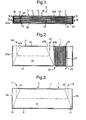
- a heat exchanger device for refrigeration dryers in compressed air systems contains after Fig. 1 to 3 in the right part of a refrigerant / air heat exchanger and in the left part an air / air heat exchanger.
- the two networks 1 and 2 are mainly by planparellele, rectangular or square plates 4 formed over the entire width and length of the block. 3 are extended. According to FIGS. 1 and 3, a part of the plates 4 is on the one hand by perpendicular to the longitudinal direction, at in Fig. 3 right and left ends of Blocks 3 arranged strips 5a and 5b and on the other hand by extending in the longitudinal direction, arranged on the side edges of the plates 4 strips 7, 8 in pairs Distance kept. This creates between these plates 4 passes 9. Am in Fig. 3 left end, the upper strips 7 are slightly shorter, so that between their left Ends and the strips 5a each gaps 10 arise through the air in Direction of an arrow 11 can enter laterally. Accordingly, the upper strip 7 at the right in Fig.
- the other part of the plates 4 is shown in FIG. 1 and 2 in the network 2 forming part by parallel to the longitudinal direction, arranged on the side edges of the plates 4 and up to the in Fig. 1 and 2 left end of the network 1 extended strips 18 and 19th as well as transversely thereto, the left and right end of the network 2 forming end strips 20a and 20b kept in pairs at a distance.
- On the sides of the end strips 20 a and 20b are the top in Fig. 2 bar 18 is slightly shorter, so that between them and the two strips 20a, 20b respectively gaps 22a, 22b arise through the air enter laterally or exit and in the direction of arrows drawn 23, 24 (Fig. 2) can be supplied or removed.
- the deflection is analogous to FIG. 3 preferably with correspondingly formed, provided in the passages 21 slats 25th causes.
- the network 1 serve the same plates 4, which limit the passages 21, for the formation of serpentine or meandering passageways 26 ( Figure 1) which are straight and the deflection serving portions and are explained in more detail below.
- the passages 26 each extend from one of the end strips 20b to one End strip 27, which is arranged in Fig. 1 and 2 at the right end of the block 3.
- plate pairs preferably alternate with the passages 9 and plate pairs with the passages 21, 26 in superimposed planes, at least each a passage 9, 21, 26 is present.
- the passages 26 at a indicated by an arrow 28 input a refrigerant supplied to a through an arrow 29 indicated output can flow out again and a not shown Flows through the refrigerant circuit.
- the compressed air is then marked at the arrow 14 ( Figure 3) Removed output and fed to a water separator, not shown, from where from the arrow 23 introduced into the network 2 and this at the by the arrow 24th indicated output is taken, which serves as a tapping point for the compressed air.
- a water separator not shown, from where from the arrow 23 introduced into the network 2 and this at the by the arrow 24th indicated output is taken, which serves as a tapping point for the compressed air.
- there the arrangement is chosen so that the air at the tap again approximately on Room temperature is heated.
- Heat exchanger devices of the type described and their mode of action are the skilled worker generally known (EP 0 521 298 A2) and therefore need not closer be explained.
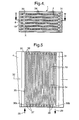
- a second exemplary embodiment of the network 1 is shown in FIG. 9, in which the channels of a variety of integrally interconnected and formed I-profiles are arranged one behind the other.
- the plates 4 each of an associated pair are spaced by ledges 30 and 31, respectively, which are transverse to a longitudinal axis 32 of the net 1 and have square or rectangular cross-sections to be plane-parallel therebetween To form cavities.
- the strip 30 can correspond to the strip 20b according to FIG.
- apparent profiles 33 are arranged with I-shaped cross-sections, which extends perpendicular to the longitudinal axis 32 and to the plates 4, mutually parallel webs 33a and at both ends thereof each have a perpendicular to the webs 33a arranged belt or flange 33b, 33c.
- Heights h of the profiles 33 correspond to the heights of the strips 30 and 31, so that in the assembled state, outer surfaces 33d, 33e ( Figure 8) of the flanges 33b, 33c are disposed on the plates above and below them 4 abut.
- the channels 34 are limited to the sides by two webs 33 a and up and down by the associated flanges 33 b, 33 c of the profiles 33. In this case, distances a (FIG.
- the profiles 33 are preferably chosen to be large enough that intermediate spaces 35 with a width b remain between the mutually facing ends of their flanges 33b, 33c, so that the channels 34 are not there from the flanges 33b and 33c but limited by these overlapping portions of the plates 4.
- the surfaces 33d, 33e are preferably slightly convex toward the outside.
- the profiles 33 are in their perpendicular to Longitudinal axis 32 extending longitudinal direction preferably the same length, but alternately offset to the front or rear relative to each other.
- the arrangement is such that the one end of a first, adjacent to the bar 30 profile 33 with a certain Distance from that in Fig. 7 lower edge of the associated plate 4 is arranged while the other end is flush with the upper edge of the plate 4 in FIG. 5.
- the intermediate profiles 33 i. the second, fourth and so on Profile, opposite the Odd numbered profiles 33 offset so that they are flush with their one ends with the in Figs.
- one of the deflection sections 36a, 36b serves to connect a connection nipple, collecting tank or the like in order to supply or remove the refrigerant in the direction of the arrows 28, 29.
- the other deflection portions 36 are, however, outwardly bounded by blocks 37, which have a height h (Fig. 6) corresponding height and a width, preferably substantially equal to the difference between the double distance a and the width of a Webs 33a in Fig.
- the blocks 37 are each in a space bounded on the one hand by the webs 33a and plates 4 and on the other hand by the mutually facing ends of the flanges 33b, 33c of those profiles 33 which border on one or the other edge of the plates 4.
- the blocks 37 abut both the webs 33a and plates 4 and at the ends of the flanges 33b, 33c.
- the attachment of the various parts together is preferably carried out by soldering in a salt bath.
- the plates 4, profiles 33 and blocks 37 are preferably made of aluminum. to Soldering of these parts together, the plates 4 and blocks 37 to the corresponding Surfaces preferably with a suitable solder plated layers, as For example, in the production of aluminum coolers is well known. Of the Soldering is also favored by the fact that the surfaces 33d, 33e of Flanges 33b, 33c are slightly curved or convex, as a result of their investment in the flat plate surfaces wedge gaps arise, which is a large-scale wetting of the Ensure that the connecting parts are secure.
- the I-shaped cross section of the profiles 33 brings the significant advantage that on the one hand at the ends of the profiles 33 comparatively large, for the soldering to Available surfaces 33d, 33e (Fig. 8) are obtained, on the other hand, the cross sections the profiles 33 in the middle parts comparatively small and therefore the Cross sections of the limited channels 34 are comparatively large. Thereby On the one hand, a high compressive strength of the channels 34 and deflecting sections 36 formed passages, on the other hand, a large effectiveness of the heat exchange achieved, because in a small space a large flow cross-section are housed can. Because of the high packing density of the channels 34, the width of the refrigerant / air Heat exchanger network 1 (Fig. 1) much shorter than before and thus the Overall device of air / air and refrigerant / air heat exchanger essential be made more compact and smaller.
- the Passages 34 do not consist of individual, juxtaposed I-profiles 33, whose webs 33a form the lateral partitions of the individual channels, but from a Variety of rigidly connected, consecutively arranged I-profiles 41st educated. Webs 41 a of the profiles 41 thereby form shelves, while with their Outer surfaces contiguous or merging flanges 41b lateral Partitions between each, transverse to the longitudinal axis 32 and parallel to each other arranged channels 42a and 42b form. As in the embodiment of FIG.
- the profiles 41 are offset in their longitudinal direction relative to each other, and the Channels 42a and 42b are at their ends on one and the other longitudinal side by Deflection sections 43a and 43b meandering or even serpentine with each other connected.
- the deflection sections 43a are outwardly through wall sections 44a, the deflection portions 43b, however, bounded by wall sections 44b, which at each Long side but only with each second flange 41b are connected, while the intermediate Flanges 41b forming the deflection portions 43a, 43b in front of these Wall sections 44 a, 44 b end, so that the individual partitions analogous to Fig. 1 to 8 are offset transversely to the longitudinal direction 32 and relative to each other. Otherwise, FIG.
- each a plurality of corresponding channels 42a and 42b is formed, the are fluidly connected in series by the deflection sections 43a, 43b and form a passage for the refrigerant.
- the channels 1 to 8 covered by the plates 4 and closed (Fig. 10), which with the side edges of the flanges 41b are connected by soldering.
- the flanges 41b are called between the grooves are permanent wall sections and the webs 41 a as stand permanent groove bottoms are obtained, all of these soils lying in one plane, the one forms over the entire width and length of the workpiece 45 extended intermediate bottom, from each of the flanges 41b each half perpendicular up or down protrude.
- the grooves only on one surface of the Workpiece 45 form, in which case a cross section through the workpiece 45th along the longitudinal axis 32 would lead to a substantially U-shaped profiling.
- the refrigerant passage could then be made up of a plurality of juxtaposed, U-shaped profiles are thought to be assembled with their lateral webs adjoin one another or merge into one another.
- this forms the refrigerant passage comprising part of an integrally manufactured, I- or U-shaped profiled Workpiece, which is used to close the channels 42a, which are initially open or open at the bottom, 42b and deflecting sections 43a, 43b on one or both sides by soldering to the plates 4th is connected.
- a reference numeral 46 is, so that not shown from the outer sides, for the supply and removal of the Refrigerant certain headers or the like can be attached.
- the soldering as in the embodiment of FIG. 1 inexpensively in a salt bath can take place, the wall sections 44a, 44b before the soldering with appropriate Slots 47 provided, which are indicated by dashed lines in Fig. 9 in some places and the Connecting deflection sections 43a, 43b with the outer sides of the wall sections 44a, 44b, i.e. enforce this.
- the channels 42a, 42b penetrate to the parts to be soldered in the region of forming Soldering soldering column, and after the soldering process just as easily back out of the channels 42a, 42b flow out.
- the slots 47 are made by a welding process locked.
- FIG. 8 the design of the network described with reference to FIG. 8 (FIG. 1) leads to a high-strength construction that can withstand high bursting pressures.
- the invention is not limited to the described embodiments, which can be modified in many ways. This is especially true for those from the Drawings apparent cross sections of I or U profiles, which also other forms and could be provided in combination.
- the invention not limited to the application of the material aluminum, as for the production of described heat exchange networks also numerous other suitable for this purpose Materials can be used.
- the networks 1 and 2 form an integral component by means of the continuous plates 4, separately manufactured and then assembled into an integral component or as separate components find application through corresponding lines with each other are connected.
- the two networks 1 and 2 on top of each other instead of side by side to arrange.
Landscapes
- Engineering & Computer Science (AREA)
- Physics & Mathematics (AREA)
- Thermal Sciences (AREA)
- Mechanical Engineering (AREA)
- General Engineering & Computer Science (AREA)
- Heat-Exchange Devices With Radiators And Conduit Assemblies (AREA)
Applications Claiming Priority (2)
| Application Number | Priority Date | Filing Date | Title |
|---|---|---|---|
| DE10151238A DE10151238A1 (de) | 2001-10-17 | 2001-10-17 | Kältemittel/Luft-Wärmeaustauschernetz |
| DE10151238 | 2001-10-17 |
Publications (2)
| Publication Number | Publication Date |
|---|---|
| EP1304536A2 true EP1304536A2 (fr) | 2003-04-23 |
| EP1304536A3 EP1304536A3 (fr) | 2004-07-21 |
Family
ID=7702786
Family Applications (1)
| Application Number | Title | Priority Date | Filing Date |
|---|---|---|---|
| EP02022853A Withdrawn EP1304536A3 (fr) | 2001-10-17 | 2002-10-14 | Système d'échange de chaleur réfrigérant / air |
Country Status (4)
| Country | Link |
|---|---|
| US (1) | US6901996B2 (fr) |
| EP (1) | EP1304536A3 (fr) |
| JP (1) | JP2003185376A (fr) |
| DE (1) | DE10151238A1 (fr) |
Cited By (4)
| Publication number | Priority date | Publication date | Assignee | Title |
|---|---|---|---|---|
| EP1770345A2 (fr) * | 2005-09-28 | 2007-04-04 | Autokühler GmbH & Co. KG | Réseau d'échange de chaleur et échangeur de chaleur comprenant celui-ci |
| BE1018518A3 (nl) * | 2009-04-06 | 2011-02-01 | Atlas Copco Airpower Nv | Verbeterde warmtewisselaar. |
| RU2476458C2 (ru) * | 2011-05-10 | 2013-02-27 | Федеральное государственное бюджетное образовательное учреждение высшего профессионального образования "Кабардино-Балкарский государственный университет им. Х.М. Бербекова" | Полимерная композиция |
| EP2244045A3 (fr) * | 2009-04-21 | 2013-03-27 | Linde Aktiengesellschaft | Échangeur thermique à plaques doté de profilés |
Families Citing this family (4)
| Publication number | Priority date | Publication date | Assignee | Title |
|---|---|---|---|---|
| US20100224173A1 (en) * | 2009-03-09 | 2010-09-09 | Herve Palanchon | Heat Exchanger with Cast Housing and Method of Making Same |
| US11346608B2 (en) * | 2016-01-29 | 2022-05-31 | Deere & Company | Heat exchanger with improved plugging resistance |
| CN105826811B (zh) * | 2016-05-06 | 2020-10-23 | 华中科技大学 | 一种可调谐激光器的表征方法及装置 |
| FR3084739B1 (fr) * | 2018-07-31 | 2020-07-17 | L'air Liquide, Societe Anonyme Pour L'etude Et L'exploitation Des Procedes Georges Claude | Echangeur de chaleur a configuration de passages amelioree, procedes d'echange de chaleur associes |
Citations (1)
| Publication number | Priority date | Publication date | Assignee | Title |
|---|---|---|---|---|
| EP0521298A2 (fr) | 1991-06-04 | 1993-01-07 | Autokühler Gmbh & Co. Kg. | Dispositif d'échange de chaleur pour séchoir par réfrigération dans les installations d'air comprimé et échangeur de chaleur à tubes et plaques pour cette application |
Family Cites Families (20)
| Publication number | Priority date | Publication date | Assignee | Title |
|---|---|---|---|---|
| US331532A (en) * | 1885-12-01 | Platen for drying apparatus | ||
| US1490706A (en) * | 1921-10-12 | 1924-04-15 | Bethlehem Steel Corp | Hot plate for presses and method of making same |
| US1571599A (en) * | 1922-03-07 | 1926-02-02 | Farrel Foundry & Machine Compa | Platen for vulcanizing presses and the like |
| US2566310A (en) * | 1946-01-22 | 1951-09-04 | Hydrocarbon Research Inc | Tray type heat exchanger |
| FR929698A (fr) * | 1946-06-24 | 1948-01-05 | Nouvel élément échangeur thermique | |
| US2874941A (en) * | 1955-09-06 | 1959-02-24 | Air Preheater | Brazed extended surface heat exchanger |
| FR1302612A (fr) * | 1961-07-20 | 1962-08-31 | Caissons échangeurs de température | |
| DE3007493C2 (de) * | 1980-02-28 | 1982-04-29 | G. Siempelkamp Gmbh & Co, 4150 Krefeld | Pressenplatte für heizbare Pressen |
| DE3107010C2 (de) * | 1981-02-25 | 1985-02-28 | Dieter Christian Steinegg-Appenzell Steeb | Metallkühler zum Kühlen eines unter hohem Druck durchströmenden Fluids durch Luft |
| DE3146088A1 (de) * | 1981-11-20 | 1983-05-26 | Linde Ag, 6200 Wiesbaden | "plattenwaermetauscher" |
| DE3717649A1 (de) * | 1987-05-26 | 1988-12-15 | Held Kurt | Doppelbandpresse mit erwaerm- oder kuehlbaren teilen und verfahren zu deren herstellung |
| DE4118289A1 (de) * | 1991-06-04 | 1992-12-10 | Autokuehler Gmbh & Co Kg | Waermetauscher-vorrichtung fuer kaeltetrockner an druckluftanlagen |
| FR2685071B1 (fr) * | 1991-12-11 | 1996-12-13 | Air Liquide | Echangeur de chaleur indirect du type a plaques. |
| BE1008176A6 (nl) * | 1994-03-07 | 1996-02-06 | Atlas Copco Airpower Nv | Werkwijze voor het drogen van een gekomprimeerd gas en inrichting om deze werkwijze te verwezenlijken. |
| DE19518511C2 (de) | 1994-05-20 | 1998-04-02 | Hermann Dipl Ing Kuenst | Verfahren zur transcutanen, unblutigen In-vivo-Konzentrationsbestimmung von Substanzen im Blut |
| WO1995033173A1 (fr) * | 1994-05-31 | 1995-12-07 | Tjiok Mouw Ching | Echangeur de chaleur et son utilisation |
| DE19547928C2 (de) * | 1995-06-30 | 1999-03-11 | Mtu Friedrichshafen Gmbh | Plattenwärmetauscher |
| US6044902A (en) * | 1997-08-20 | 2000-04-04 | Praxair Technology, Inc. | Heat exchange unit for a cryogenic air separation system |
| JP2000108655A (ja) * | 1998-01-13 | 2000-04-18 | Denso Corp | 除湿装置 |
| DE29822888U1 (de) * | 1998-12-23 | 1999-02-25 | Steeb Industriekuehler Albert | Platten-Leisten-Kühlblock |
-
2001
- 2001-10-17 DE DE10151238A patent/DE10151238A1/de not_active Withdrawn
-
2002
- 2002-10-14 EP EP02022853A patent/EP1304536A3/fr not_active Withdrawn
- 2002-10-17 JP JP2002303012A patent/JP2003185376A/ja active Pending
- 2002-10-17 US US10/272,838 patent/US6901996B2/en not_active Expired - Fee Related
Patent Citations (1)
| Publication number | Priority date | Publication date | Assignee | Title |
|---|---|---|---|---|
| EP0521298A2 (fr) | 1991-06-04 | 1993-01-07 | Autokühler Gmbh & Co. Kg. | Dispositif d'échange de chaleur pour séchoir par réfrigération dans les installations d'air comprimé et échangeur de chaleur à tubes et plaques pour cette application |
Cited By (7)
| Publication number | Priority date | Publication date | Assignee | Title |
|---|---|---|---|---|
| EP1770345A2 (fr) * | 2005-09-28 | 2007-04-04 | Autokühler GmbH & Co. KG | Réseau d'échange de chaleur et échangeur de chaleur comprenant celui-ci |
| EP1770345A3 (fr) * | 2005-09-28 | 2008-12-17 | Autokühler GmbH & Co. KG | Réseau d'échange de chaleur et échangeur de chaleur comprenant celui-ci |
| BE1018518A3 (nl) * | 2009-04-06 | 2011-02-01 | Atlas Copco Airpower Nv | Verbeterde warmtewisselaar. |
| WO2010115246A3 (fr) * | 2009-04-06 | 2011-03-03 | Atlas Copco Airpower | Échangeur de chaleur amélioré |
| US9574828B2 (en) | 2009-04-06 | 2017-02-21 | Atlas Copco Airpower Naamloze Vennootschap | Heat exchanger |
| EP2244045A3 (fr) * | 2009-04-21 | 2013-03-27 | Linde Aktiengesellschaft | Échangeur thermique à plaques doté de profilés |
| RU2476458C2 (ru) * | 2011-05-10 | 2013-02-27 | Федеральное государственное бюджетное образовательное учреждение высшего профессионального образования "Кабардино-Балкарский государственный университет им. Х.М. Бербекова" | Полимерная композиция |
Also Published As
| Publication number | Publication date |
|---|---|
| JP2003185376A (ja) | 2003-07-03 |
| DE10151238A1 (de) | 2003-04-30 |
| US20030070795A1 (en) | 2003-04-17 |
| US6901996B2 (en) | 2005-06-07 |
| EP1304536A3 (fr) | 2004-07-21 |
Similar Documents
| Publication | Publication Date | Title |
|---|---|---|
| EP0521298B1 (fr) | Dispositif d'échange de chaleur pour séchoir par réfrigération dans les installations d'air comprimé | |
| DE102005015799B4 (de) | Kältemittelverdampfer | |
| DE69922984T2 (de) | Plattenwärmetauscher | |
| DE2442420C3 (de) | Desublimator für die Gewinnung von Sublimationsprodukten, insbesondere von Phthalsäureanhydrid, aus Reaktionsgasen | |
| EP1856734B1 (fr) | Micro-echangeur de chaleur | |
| DE19644586C2 (de) | Rippenrohrblock für einen Wärmeübertrager | |
| EP0917638A1 (fr) | Bac distributeur et collecteur de l'evaporateur a au moins deux flux du systeme de climatisation d'un vehicule a moteur | |
| DE10118625A1 (de) | Wellenförmige Lamelle mit teilweisem Versatz für Plattenwärmetauscher | |
| DE112005001295T5 (de) | Wärmetauscher | |
| EP1792135B1 (fr) | Echangeur thermique pour vehicules a moteur | |
| EP1770345B1 (fr) | Réseau d'échange de chaleur et échangeur de chaleur comprenant celui-ci | |
| DE19543149C2 (de) | Wärmetauscher, insbesondere Kältemittelverdampfer | |
| DE19719259A1 (de) | Flachrohrwärmetauscher für Kraftfahrzeuge mit an Krägen eines Rohrbodens gehaltenen Flachrohren | |
| DE19814051A1 (de) | Geschichteter Wärmetauscher | |
| AT513177B1 (de) | Plattenwärmeübertrager, insbesondere für Absorptionskälteanlagen | |
| EP1304536A2 (fr) | Système d'échange de chaleur réfrigérant / air | |
| DE10020763A1 (de) | Starken Innendrücken widerstehendes längliches Sammlergehäuse für Wärmetauscher | |
| EP1477761B1 (fr) | Échangeur de chaleur à plaques | |
| DE3143334C2 (fr) | ||
| DE3906747A1 (de) | Ladeluftkuehler | |
| EP1588114B1 (fr) | Échangeur de chaleur à couches à contre-courant et courant croisé | |
| DE4118289A1 (de) | Waermetauscher-vorrichtung fuer kaeltetrockner an druckluftanlagen | |
| EP0910778B1 (fr) | Evaporateur a tubes aplatis verticaux pour vehicules a moteur | |
| DE19846347C2 (de) | Wärmeaustauscher aus Aluminium oder einer Aluminium-Legierung | |
| EP3507046B1 (fr) | Procede de fabrication d'un bloc d'echangeur de chaleur a plaques consistant en l'application ciblee de materiau a braser, en particulier sur des ailettes et barres laterales |
Legal Events
| Date | Code | Title | Description |
|---|---|---|---|
| PUAI | Public reference made under article 153(3) epc to a published international application that has entered the european phase |
Free format text: ORIGINAL CODE: 0009012 |
|
| AK | Designated contracting states |
Designated state(s): AT BE BG CH CY CZ DE DK EE ES FI FR GB GR IE IT LI LU MC NL PT SE SK TR |
|
| AX | Request for extension of the european patent |
Extension state: AL LT LV MK RO SI |
|
| PUAL | Search report despatched |
Free format text: ORIGINAL CODE: 0009013 |
|
| AK | Designated contracting states |
Kind code of ref document: A3 Designated state(s): AT BE BG CH CY CZ DE DK EE ES FI FR GB GR IE IT LI LU MC NL PT SE SK TR |
|
| AX | Request for extension of the european patent |
Extension state: AL LT LV MK RO SI |
|
| 17P | Request for examination filed |
Effective date: 20050120 |
|
| AKX | Designation fees paid |
Designated state(s): AT BE BG CH CY CZ DE DK EE ES FI FR GB GR IE IT LI LU MC NL PT SE SK TR |
|
| 17Q | First examination report despatched |
Effective date: 20050427 |
|
| STAA | Information on the status of an ep patent application or granted ep patent |
Free format text: STATUS: THE APPLICATION IS DEEMED TO BE WITHDRAWN |
|
| 18D | Application deemed to be withdrawn |
Effective date: 20050908 |