EP1477761B1 - Échangeur de chaleur à plaques - Google Patents
Échangeur de chaleur à plaques Download PDFInfo
- Publication number
- EP1477761B1 EP1477761B1 EP04007595.4A EP04007595A EP1477761B1 EP 1477761 B1 EP1477761 B1 EP 1477761B1 EP 04007595 A EP04007595 A EP 04007595A EP 1477761 B1 EP1477761 B1 EP 1477761B1
- Authority
- EP
- European Patent Office
- Prior art keywords
- plate
- heat exchanger
- exchanger according
- channels
- seal
- Prior art date
- Legal status (The legal status is an assumption and is not a legal conclusion. Google has not performed a legal analysis and makes no representation as to the accuracy of the status listed.)
- Expired - Lifetime
Links
- 238000010438 heat treatment Methods 0.000 claims description 18
- 239000002826 coolant Substances 0.000 claims description 11
- 238000003825 pressing Methods 0.000 claims description 3
- 239000011552 falling film Substances 0.000 description 4
- 239000010408 film Substances 0.000 description 4
- 238000007789 sealing Methods 0.000 description 4
- 238000001704 evaporation Methods 0.000 description 3
- 230000008020 evaporation Effects 0.000 description 3
- 238000007373 indentation Methods 0.000 description 2
- 239000002131 composite material Substances 0.000 description 1
- 210000005069 ears Anatomy 0.000 description 1
- 230000000694 effects Effects 0.000 description 1
- 230000002349 favourable effect Effects 0.000 description 1
- 238000004519 manufacturing process Methods 0.000 description 1
- 239000008267 milk Substances 0.000 description 1
- 210000004080 milk Anatomy 0.000 description 1
- 235000013336 milk Nutrition 0.000 description 1
- 239000000203 mixture Substances 0.000 description 1
- 230000002093 peripheral effect Effects 0.000 description 1
- 230000000630 rising effect Effects 0.000 description 1
- 238000000926 separation method Methods 0.000 description 1
- 230000007704 transition Effects 0.000 description 1
- 230000001960 triggered effect Effects 0.000 description 1
- 238000013022 venting Methods 0.000 description 1
Images


Classifications
-
- F—MECHANICAL ENGINEERING; LIGHTING; HEATING; WEAPONS; BLASTING
- F28—HEAT EXCHANGE IN GENERAL
- F28F—DETAILS OF HEAT-EXCHANGE AND HEAT-TRANSFER APPARATUS, OF GENERAL APPLICATION
- F28F3/00—Plate-like or laminated elements; Assemblies of plate-like or laminated elements
- F28F3/08—Elements constructed for building-up into stacks, e.g. capable of being taken apart for cleaning
- F28F3/083—Elements constructed for building-up into stacks, e.g. capable of being taken apart for cleaning capable of being taken apart
-
- B—PERFORMING OPERATIONS; TRANSPORTING
- B01—PHYSICAL OR CHEMICAL PROCESSES OR APPARATUS IN GENERAL
- B01D—SEPARATION
- B01D1/00—Evaporating
- B01D1/22—Evaporating by bringing a thin layer of the liquid into contact with a heated surface
- B01D1/221—Composite plate evaporators
-
- F—MECHANICAL ENGINEERING; LIGHTING; HEATING; WEAPONS; BLASTING
- F28—HEAT EXCHANGE IN GENERAL
- F28D—HEAT-EXCHANGE APPARATUS, NOT PROVIDED FOR IN ANOTHER SUBCLASS, IN WHICH THE HEAT-EXCHANGE MEDIA DO NOT COME INTO DIRECT CONTACT
- F28D9/00—Heat-exchange apparatus having stationary plate-like or laminated conduit assemblies for both heat-exchange media, the media being in contact with different sides of a conduit wall
- F28D9/0031—Heat-exchange apparatus having stationary plate-like or laminated conduit assemblies for both heat-exchange media, the media being in contact with different sides of a conduit wall the conduits for one heat-exchange medium being formed by paired plates touching each other
- F28D9/0043—Heat-exchange apparatus having stationary plate-like or laminated conduit assemblies for both heat-exchange media, the media being in contact with different sides of a conduit wall the conduits for one heat-exchange medium being formed by paired plates touching each other the plates having openings therein for circulation of at least one heat-exchange medium from one conduit to another
- F28D9/005—Heat-exchange apparatus having stationary plate-like or laminated conduit assemblies for both heat-exchange media, the media being in contact with different sides of a conduit wall the conduits for one heat-exchange medium being formed by paired plates touching each other the plates having openings therein for circulation of at least one heat-exchange medium from one conduit to another the plates having openings therein for both heat-exchange media
-
- F—MECHANICAL ENGINEERING; LIGHTING; HEATING; WEAPONS; BLASTING
- F28—HEAT EXCHANGE IN GENERAL
- F28F—DETAILS OF HEAT-EXCHANGE AND HEAT-TRANSFER APPARATUS, OF GENERAL APPLICATION
- F28F3/00—Plate-like or laminated elements; Assemblies of plate-like or laminated elements
- F28F3/02—Elements or assemblies thereof with means for increasing heat-transfer area, e.g. with fins, with recesses, with corrugations
- F28F3/04—Elements or assemblies thereof with means for increasing heat-transfer area, e.g. with fins, with recesses, with corrugations the means being integral with the element
Definitions
- the invention relates to a plate heat exchanger acting as evaporator and / or condenser according to the preamble of claim 1.
- Such heat exchanger plates are stacked into a package so that alternately the product or the heating / cooling medium flows in the plate interspaces. They are known in a variety of designs and profiles and are characterized by the high heat transfer performance due to the gap flow.
- passages are arranged in the four corners of the plate, such that two diagonally opposite openings serve as inflow and outflow for one medium, while the other two diagonally opposite openings are separated by seals relative to this first medium and for the flow of the second Serve medium to the next plate gap.
- a heat transfer plate for pasteurizing milk has become known, which has a heat transfer area and edge seals. The seals are laid so that through openings are assigned to the respective medium and the respective side of the plate. On the longitudinal sides of the heat exchanger plate channels for the heating or cooling medium are arranged at the bottom and top.
- a heat exchanger plate which comprises a substantially rectangular heat transfer region with seals. Further, a plurality of inlet and outlet openings are arranged on the plate transverse sides.
- the present invention has the object to bring about a more uniform loading of the plate gap by the inflowing medium and thus homogeneous conditions for heat transfer and for the product temperature.
- the new plate should be characterized by cost-effective production and high reliability.
- the plates of the plate heat exchanger according to the invention have at the longitudinal edges in each case a plurality of longitudinally juxtaposed side by side steam channels and a condensate channel for the heating or cooling medium.
- These steam channels and the condensate channel are no longer formed by so-called “protruding ears" as before, but lie within the approximately rectangular plate contour, preferably the entire longitudinal edge - one or both sides of the plate - is formed by steam and condensate channels.
- This provides several integrated into the plate steam channels provides the essential Advantage that steam channels can be internally - thus connected within the plate stack with each other. The previously necessary, externally mounted deflection lines and connections are unnecessary. Instead, one only needs to omit the seal between adjacent vapor channels on some plates until a transition region of sufficient cross-section is available.
- the aforementioned internal connectivity is also for the condensate channels into consideration.
- the inflow openings can extend almost over the entire width of the heat transfer area and thus cause a considerably more uniform loading of the plate gap across its width. Temperature differences in the transverse direction of the plate gap are thereby virtually eliminated and the heat treatment of the product becomes more reproducible and precise than before.
- the inlet openings could also be arranged over the corner. However, it is particularly expedient if they are arranged only along a plate narrow side and extend over almost the entire width of the heat transfer area. In particular, the inlet openings should therefore lie next to one another on the same side of the plate and without sealed throughflow openings arranged therebetween for the other medium.
- the seal arranged on the outside of the inlet openings in each case runs into the intermediate space between adjacent inlet openings.
- pressure loss generating cross flows and mixing between the incoming streams are avoided.
- the said seal should run around the inlet openings so that it offers at each inflow opening extending in the direction of the heat transfer area flow cross-section.
- the seal should So only run around the outer peripheral portion of the inflow and extend to the plate gap, so that there obliquely into the gap running guide edges forms in the sense of fanning the flow cross-section of the smaller flow width in the inflow to a larger flow width in the plate gap.
- the individual flows thus receive an optimal alignment towards the heat transfer area.
- Another expedient development of the invention consists in profiling the heat transfer area at least in the plate half assigned to the inflow openings in such a way that, in combination with the profiling of the neighboring plate, a multiplicity of plate channels extending in the longitudinal direction of the plate results. So here you consciously dispensed with the attachment oblique ribs, grid-shaped projections distributed and thereby triggered distraction of the flow to get along with the lowest possible pressure loss. This embodiment is therefore particularly suitable for evaporation of the product under vacuum.
- the subsequent residual heat transfer area which is assigned to the effective on the other side of the plate inlet openings of the heating medium, preferably has a different profiling, and indeed one which allows both longitudinal and transverse flows on the Schumediumseite.
- the possible transverse flow on the back of the plate favors the distribution of the heating medium coming from the outside over the entire plate width.
- two relatively large outflow openings are provided in the plate.
- the condensate channel is surrounded by a seal which encloses an area which is at least 50%, preferably at least 75% of that area enclosed by the seal of the condensate channel farthest steam channel becomes.
- the condensate channel can be cut much larger from the plate as it would be necessary for the pure condensate discharge, in particular, the condensate channel be made with a similar large cross-section as a steam channel.
- the condensate channel optional can also be used as a steam channel. That is, the same plate can be used either as a rising film or as a falling film evaporator. It only needs to be rotated 180 degrees about its transverse axis.
- the described oversizing of the area enclosed by the seal of the condensate channel also offers the possibility of providing a further channel for condensate venting within this area and above the condensate channel. This can be dispensed with an air separator outside the plate heat exchanger.
- the juxtaposed steam channels make it possible to use unused steam channels for drawing in tensioning devices for compressing the plate pack.
- the plate in a conventional manner at least on one side has a substantially longitudinally continuous seal, such that two separately juxtaposed flow cross sections arise.
- This separation can also be realized in the form that the plate is divided in the central longitudinal direction into two separate plate halves, which fit together in the composite with divided or undivided plates.
- the advantage of such split plates is that due to the smaller plate area even smaller pressing forces are needed and that the system can be customized more individually to the needs of the user, for example by two evaporator stages are driven with only one apparatus.
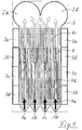
- the plate has a substantially rectangular outer contour.
- the product feed takes place in Fig. 1 via four adjacently arranged on the lower narrow side of the plate and evenly distributed over this narrow side inflow openings 1a to 1d, while the vapor product discharge via two outlet openings 2a, 2b, which are arranged on the upper narrow plate side and each extending almost over half the plate width.
- the plate On the two longitudinal sides of the plate, four approximately rectangular channels are arranged within the rectangular plate contour, which serve in the embodiment for the supply and discharge of a heating medium.
- the three upper channels 3a, 3b, 3c of each side function as vapor channels, whereas the lower channel 3d of each side serves as a condensate channel.
- the channels are arranged directly above one another.
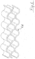
- a wave-shaped profiling 4b which in FIG. 6 is shown. It is designed and oriented in conjunction with the corresponding profiling of the neighboring plate so that a large number of small, straight-line partial flows in the longitudinal direction of the plate is created, through which the product flows upwards. A cross-flow is provided here neither for the product nor for the heating or cooling medium, but can by denting as in FIG. 5 be allowed.
- the wavy profiling 4b extends approximately over two thirds of the height of the heat transfer area.
- the remaining upper area is formed by a profiling 4c, which allows longitudinal and transverse flows of the product as well as the heating or cooling medium. This area is at the height of the upper steam channels 3a.
- the gasket 5 is placed so that the heat transfer area 4 is connected to the inlet openings 1a to 1d and to the outlet openings 2a and 2b for the product, whereas the steam and condensate channels 3a to 3d are shut off from the heat transfer area.
- the seal 5 runs approximately funnel-shaped around the inflow openings 1a to 1d, such that the flow width from the inflow opening to the heat transfer area 4 increases steadily until the seal kinks in order to bypass the next inflow opening in a funnel shape. In this way, the flows coming from the inlet openings 1a to 1d are distributed uniformly over the full width of the heat transfer area 4.
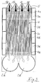
- FIG. 2 shows the back of the plate according to Fig. 1 , It can be seen that the seal 5 is laid here so that the inflow channels 1a to 1d and the product outflow passages 2a, 2b are shut off from the heat transfer face 4 and instead the upper vapor passages 3a and 3d lower passages acting as condensate passages , are connected to the heat transfer area 4.
- the upper heat transfer area 4c which allows cross flows, is important to the two sides distribute steam flowing in from the channels 3a over the width of the plate. The same applies to the lower heat transfer area 4a, because there the condensate must be directed outward again into the condensate channels 3d.
- the seal 5 blocks the steam channels 3b and 3c not only with respect to the heat transfer area 4, but also with each other and to the outside, so that these channels can optionally be used for a second heating or coolant circuit.
- the Figures 3 and 4 show the use of the plate according to the invention as a falling film evaporator. That is, the product-side inflow openings 1a to 1d are now arranged on the upper narrow plate side and the product-side outflow openings 2a and 2b on the lower narrow plate side. It is essential that the indentations for the seal 5 coincide identically with the previously described application of the film evaporator according to FIG. 1 and 2 , It is therefore possible to work with almost the same plates for both applications and only needs to rotate them 180 degrees around their transverse axis.
- This heat transfer area 4c in the upper plate area namely at the level of the steam supply channels 3a, cf. Fig. 4 , has the appropriate in FIG. 5 profiling shown, that is, that on the product side only currents in the longitudinal direction of the plate are allowed, on the other hand, both in Longitudinal as well as in the transverse direction.
- the lower heat transfer area 4a essentially retains its position, but now leads to the product-side outflow openings 2a, 2b or to the condensate channels 3d and allows both longitudinal and transverse flows to.
- the plates have top and bottom recesses for mounting in pressure racks. These recesses, which are not shown in the drawing, expediently have the same contour so that the above-described rotation of the plates about their transverse axis is easily possible.
- every other plate is rotated 180 degrees about its longitudinal axis so that the plates are back-to-back. If the seal groove is in the center plane of each plate, a seal of the same height can be used on the product and steam sides. On the other hand, if the sealing plane is in a zero plane, the seal of the vapor plate can be replaced by a weld, soldered connection or the like.
Landscapes
- Engineering & Computer Science (AREA)
- Physics & Mathematics (AREA)
- Thermal Sciences (AREA)
- Mechanical Engineering (AREA)
- General Engineering & Computer Science (AREA)
- Chemical & Material Sciences (AREA)
- Chemical Kinetics & Catalysis (AREA)
- Heat-Exchange Devices With Radiators And Conduit Assemblies (AREA)
Claims (17)
- Echangeur thermique à plaques qui fonctionne comme évaporateur et/ou condenseur, comprenant plusieurs plaques empilées, les plaques présentant chacune une zone de transfert de chaleur (4) et des ouvertures de passage (1, 2, 3) sur les bords pour les fluides de transfert thermique, à savoir un produit à évaporer ou à condenser au moins partiellement d'une part et un fluide de chauffage ou de refroidissement d'autre part et, à travers des joints (5) posés de façon correspondante, un groupe d'ouvertures de passage étant associé à un fluide et à un côté de la plaque respective, un autre groupe d'ouvertures de passage à l'autre fluide et à l'autre côté de la plaque respective, le groupe d'ouvertures de passage associé au produit à évaporer du côté admission de la plaque respective étant composé d'une pluralité d'ouvertures d'admission (1a à 1d) disposées les unes à côté des autres, qui débouchent, dans une direction quasi perpendiculaire au bord de plaque adjacent, directement dans la zone de transfert de chaleur (4) de la plaque, et le groupe d'ouvertures de passage (3) associé au fluide de chauffage ou de refroidissement formant le long d'au moins un bord longitudinal de la plaque respective plusieurs canaux disposés les uns à côté des autres dans la direction longitudinale de la plaque pour le fluide de chauffage ou de refroidissement, un des canaux étant conçu comme canal de condensat (3d) et les autres canaux comme canaux de vapeur (3a à 3c) et disposés le long des bords longitudinaux des plaques,
caractérisé en ce
que les canaux de vapeur (3a à 3c) et le canal de condensat (3d) sont disposés directement les uns à côté des autres et que les joints (5) sont posés de telle sorte qu'un des canaux de vapeur (3a) et le canal de condensat (3d) soient raccordés à la zone de transfert de chaleur et les autres canaux de vapeur (3b, 3c) soient fermés non seulement par rapport à la zone de transfert de chaleur (4), mais aussi les uns par rapport aux autres et vers l'extérieur, afin que ces canaux puissent être utilisés le cas échéant pour un deuxième circuit de chauffage ou de refroidissement, et que des canaux de vapeur (3a à 3c) adjacents sur plusieurs plaques puissent être reliés entre eux de manière interne par omission de leur joint intermédiaire (5). - Echangeur thermique à plaques selon la revendication 1,
caractérisé en ce
que les ouvertures d'admission (1a à 1d) du produit à évaporer sont disposées le long d'un petit côté des plaques. - Echangeur thermique à plaques selon la revendication 1,
caractérisé en ce
que les ouvertures d'admission (1a à 1d) du produit à évaporer s'étendent quasiment sur toute la largeur de la zone de transfert de chaleur. - Echangeur thermique à plaques selon la revendication 1,
caractérisé en ce
que le joint (5) disposé extérieurement sur les ouvertures d'admission pénètre chaque fois dans l'intervalle entre des ouvertures d'admission (1a à 1d) adjacentes. - Echangeur thermique à plaques selon la revendication 4,
caractérisé en ce que ledit joint (5) pénètre plus loin dans l'intervalle que ce qui correspond au diamètre des ouvertures d'admission. - Echangeur thermique à plaques selon la revendication 4 ou 5,
caractérisé en ce que ledit joint (5) s'étend en formant des sections transversales d'écoulement s'élargissant chaque fois en direction de la zone de transfert de chaleur (4). - Echangeur thermique à plaques selon la revendication 1,
caractérisé en ce
que la zone de transfert de chaleur (4) présente au moins dans la moitié de plaque associée aux ouvertures d'admission un profilage (4b) qui, en combinaison avec le profilage de la plaque voisine, produit une pluralité de canaux individuels quasiment rectilignes. - Echangeur thermique à plaques selon la revendication 7,
caractérisé en ce
que lesdits canaux individuels s'étendent dans la direction longitudinale des plaques. - Echangeur thermique à plaques selon la revendication 1,
caractérisé en ce
que la zone de transfert de chaleur (4c) présente un profilage autorisant un écoulement aussi bien transversal que longitudinal en direction de la ou des ouvertures d'admission (3a) du fluide de chauffage. - Echangeur thermique à plaques selon la revendication 1,
caractérisé en ce
qu'au moins un des deux bords longitudinaux des plaques est formé quasiment sur toute la longueur par des canaux de vapeur et de condensat (3a à 3c). - Echangeur thermique à plaques selon la revendication 1,
caractérisé en ce
que le canal de condensat (3d) est entouré par un joint (5) qui enclos une surface qui est égale à au moins 50 %, de préférence au moins 75 % de la surface qui est enclose par le joint (5) du canal de vapeur (3a) le plus éloigné du canal de condensat. - Echangeur thermique à plaques selon la revendication 11,
caractérisé en ce
que le canal de condensat (3d) est à former dans la taille souhaitée à partir de la surface enclose par le joint (5). - Echangeur thermique à plaques selon la revendication 11,
caractérisé en ce
qu'un canal (3d') protégé par rapport à la zone de transfert de chaleur (4) est formé à l'intérieur du canal de condensat (3d), dans la zone supérieure, par une portion de joint (5a), pour la purge d'air du condensat. - Echangeur thermique à plaques selon la revendication 1,
caractérisé en ce
que des moyens de serrage pour presser plusieurs plaques les unes contre les autres sont posés à l'intérieur d'un canal de vapeur (3a à 3c) inutilisé. - Echangeur thermique à plaques selon la revendication 1,
caractérisé en ce
que les plaques présentent, au moins sur un côté, un joint à peu près central s'étendant de façon continue dans la direction longitudinale pour former deux sections transversales d'écoulement disposées l'une à côté de l'autre. - Echangeur thermique à plaques selon la revendication 1,
caractérisé en ce
que les plaques sont chaque fois divisées dans la direction longitudinale médiane en deux moitiés de plaque séparées qui s'adaptent en association avec des plaques divisées ou non divisées. - Echangeur thermique à plaques selon la revendication 16,
caractérisé en ce
que des moyens de serrage pour presser l'un contre l'autre les deux paquets de plaques adjacents sont posés entre les moitiés de plaque.
Applications Claiming Priority (2)
| Application Number | Priority Date | Filing Date | Title |
|---|---|---|---|
| DE10322406 | 2003-05-16 | ||
| DE10322406A DE10322406A1 (de) | 2003-05-16 | 2003-05-16 | Platten-Wärmeübertrager |
Publications (3)
| Publication Number | Publication Date |
|---|---|
| EP1477761A2 EP1477761A2 (fr) | 2004-11-17 |
| EP1477761A3 EP1477761A3 (fr) | 2007-07-25 |
| EP1477761B1 true EP1477761B1 (fr) | 2016-11-02 |
Family
ID=33016440
Family Applications (1)
| Application Number | Title | Priority Date | Filing Date |
|---|---|---|---|
| EP04007595.4A Expired - Lifetime EP1477761B1 (fr) | 2003-05-16 | 2004-03-30 | Échangeur de chaleur à plaques |
Country Status (8)
| Country | Link |
|---|---|
| US (1) | US7055588B2 (fr) |
| EP (1) | EP1477761B1 (fr) |
| JP (1) | JP2004340569A (fr) |
| CA (1) | CA2465599C (fr) |
| DE (1) | DE10322406A1 (fr) |
| DK (1) | DK1477761T3 (fr) |
| PL (1) | PL1477761T3 (fr) |
| PT (1) | PT1477761T (fr) |
Families Citing this family (12)
| Publication number | Priority date | Publication date | Assignee | Title |
|---|---|---|---|---|
| US7820725B2 (en) * | 2006-09-05 | 2010-10-26 | Velocys, Inc. | Integrated microchannel synthesis and separation |
| DE102007015171A1 (de) * | 2007-03-27 | 2008-10-02 | Rwth Aachen | Membranvorrichtung und Verfahren zur Herstellung einer Membranvorrichtung |
| GB0715979D0 (en) * | 2007-08-15 | 2007-09-26 | Rolls Royce Plc | Heat exchanger |
| DE102008029096B4 (de) * | 2008-06-20 | 2010-04-15 | Voith Patent Gmbh | Verdampfer für ein Abwärmenutzungssystem |
| US8011191B2 (en) | 2009-09-30 | 2011-09-06 | Thermo Fisher Scientific (Asheville) Llc | Refrigeration system having a variable speed compressor |
| US8011201B2 (en) * | 2009-09-30 | 2011-09-06 | Thermo Fisher Scientific (Asheville) Llc | Refrigeration system mounted within a deck |
| ITMI20110465A1 (it) * | 2011-03-24 | 2012-09-25 | Rosella Rizzonelli | Dispositivo scambiatore di calore. |
| CN104067081B (zh) | 2012-01-27 | 2017-04-05 | 开利公司 | 蒸发器和液体分布器 |
| DE102013019478B3 (de) * | 2013-11-20 | 2015-01-22 | Modine Manufacturing Company | Wärmetauscheranordnung |
| DE102014001499A1 (de) * | 2014-02-06 | 2015-08-06 | Api Schmidt-Bretten Gmbh & Co. Kg | Zum Wärme- und/oder Stoffaustausch geeigneter Plattenapparat |
| EP3150952A1 (fr) | 2015-10-02 | 2017-04-05 | Alfa Laval Corporate AB | Plaque de transfert de chaleur et échangeur de chaleur à plaques |
| CN110566925B (zh) * | 2019-08-29 | 2023-10-31 | 浙江镭弘激光科技有限公司 | 一种蒸汽发生器 |
Citations (1)
| Publication number | Priority date | Publication date | Assignee | Title |
|---|---|---|---|---|
| GB584772A (en) * | 1944-12-18 | 1947-01-22 | R A Lister And Company Ltd | Improvements in or relating to heat-exchangers |
Family Cites Families (20)
| Publication number | Priority date | Publication date | Assignee | Title |
|---|---|---|---|---|
| US2248933A (en) | 1937-03-29 | 1941-07-15 | Astle William | Plate heat exchanger |
| FR834829A (fr) | 1937-08-20 | 1938-12-02 | Breil & Martel | échangeur de température présentant des perfectionnements à ces appareils et aux éléments ou plaques composant ceux-ci |
| GB961419A (en) * | 1960-11-10 | 1964-06-24 | Separator Ab | Plate heat exchanger |
| JPS56993A (en) * | 1979-06-13 | 1981-01-08 | Hisaka Works Ltd | Plate-type heat exchanger |
| JPS6048202B2 (ja) * | 1982-02-04 | 1985-10-25 | 株式会社日阪製作所 | 液流下型プレ−ト式蒸発器 |
| DE3220774C2 (de) | 1982-06-02 | 1986-09-25 | W. Schmidt GmbH & Co KG, 7518 Bretten | Plattenverdampfer oder -kondensator |
| DE3244547A1 (de) * | 1982-12-02 | 1984-06-07 | Gea Ahlborn Gmbh & Co Kg, 3203 Sarstedt | Waermeaustauscher |
| DE3641458A1 (de) * | 1986-12-04 | 1988-06-09 | Funke Waerme Apparate Kg | Plattenwaermeaustauscher |
| GB8811539D0 (en) * | 1988-05-16 | 1988-06-22 | Atomic Energy Authority Uk | Heat exchanger |
| DE3905066A1 (de) * | 1989-02-18 | 1990-08-23 | Behringwerke Ag | Waermetauschermodul |
| JPH07280472A (ja) * | 1994-04-12 | 1995-10-27 | Mitsubishi Heavy Ind Ltd | プレート式流下薄膜蒸発装置 |
| FI100209B (fi) * | 1994-09-27 | 1997-10-15 | Hadwaco Tech Oy | Lämmönvaihdin |
| DE19617396C2 (de) * | 1996-05-02 | 1998-03-26 | Dornier Gmbh | Strömungsmodul |
| JPH1054679A (ja) * | 1996-08-12 | 1998-02-24 | Hisaka Works Ltd | 自己循環式蒸発装置用プレート |
| DE19719257C2 (de) * | 1997-05-07 | 2002-09-19 | Valeo Klimatech Gmbh & Co Kg | Sammelkasten eines Verdampfers in Flachrohr- oder Plattenbauweise für eine Kraftfahrzeugklimaanlage und Herstellungsverfahren |
| SE516178C2 (sv) * | 2000-03-07 | 2001-11-26 | Alfa Laval Ab | Värmeöverföringsplatta, plattpaket, plattvärmväxlare samt användning av platta respektive plattpaket för framställning av plattvärmeväxlare |
| SE516416C2 (sv) | 2000-05-19 | 2002-01-15 | Alfa Laval Ab | Plattpaket, värmeöverföringsplatta, plattvärmeväxlaresamt anv ändning av värmeöverföringsplatta |
| SE518256C2 (sv) * | 2001-01-04 | 2002-09-17 | Alfa Laval Ab | Värmeöverföringsplatta, plattpaket samt plattvärmeväxlare |
| US20030111814A1 (en) | 2001-12-19 | 2003-06-19 | Sutton Craig V. | Automotive independent suspension system using beam spring |
| US7650935B2 (en) * | 2001-12-21 | 2010-01-26 | Behr Gmbh & Co. Kg | Heat exchanger, particularly for a motor vehicle |
-
2003
- 2003-05-16 DE DE10322406A patent/DE10322406A1/de not_active Withdrawn
-
2004
- 2004-03-30 EP EP04007595.4A patent/EP1477761B1/fr not_active Expired - Lifetime
- 2004-03-30 PT PT40075954T patent/PT1477761T/pt unknown
- 2004-03-30 DK DK04007595.4T patent/DK1477761T3/en active
- 2004-03-30 PL PL04007595T patent/PL1477761T3/pl unknown
- 2004-04-29 CA CA2465599A patent/CA2465599C/fr not_active Expired - Lifetime
- 2004-05-14 US US10/846,397 patent/US7055588B2/en not_active Expired - Lifetime
- 2004-05-17 JP JP2004146232A patent/JP2004340569A/ja active Pending
Patent Citations (1)
| Publication number | Priority date | Publication date | Assignee | Title |
|---|---|---|---|---|
| GB584772A (en) * | 1944-12-18 | 1947-01-22 | R A Lister And Company Ltd | Improvements in or relating to heat-exchangers |
Also Published As
| Publication number | Publication date |
|---|---|
| CA2465599A1 (fr) | 2004-11-16 |
| US7055588B2 (en) | 2006-06-06 |
| PT1477761T (pt) | 2016-12-16 |
| EP1477761A3 (fr) | 2007-07-25 |
| DK1477761T3 (en) | 2017-01-09 |
| EP1477761A2 (fr) | 2004-11-17 |
| CA2465599C (fr) | 2012-02-07 |
| DE10322406A1 (de) | 2004-12-02 |
| PL1477761T3 (pl) | 2017-09-29 |
| US20040251003A1 (en) | 2004-12-16 |
| JP2004340569A (ja) | 2004-12-02 |
Similar Documents
| Publication | Publication Date | Title |
|---|---|---|
| DE69626295T2 (de) | Plattenwärmetauscher | |
| EP1400772B1 (fr) | Echangeur de chaleur à plaques | |
| DE69106291T2 (de) | Plattenverdampfer. | |
| DE69513824T2 (de) | Plattenwärmetauscher mit drei kreisläufen | |
| DE3856032T3 (de) | Wärmetauscher mit verbesserter Kondensatsammlung | |
| DE69316121T2 (de) | Plattenwärmetauscher | |
| DE60130274T2 (de) | Wärmetauscher mit paralleler Fluidströmung | |
| DE3877215T2 (de) | Plattenwaermetauscher mit fest verbundenen platten. | |
| DE19802012C2 (de) | Gehäuseloser Plattenwärmetauscher | |
| WO1998050740A1 (fr) | Bac distributeur et collecteur de l'evaporateur a au moins deux flux du systeme de climatisation d'un vehicule a moteur | |
| DE112012004508T5 (de) | Flacher Ladeluftkühler mit geteilter Strömung und mit Austrittsverteiler mit gleichförmiger Strömung | |
| DE102004036951A1 (de) | Wärmeübertrager sowie Verfahren zu dessen Herstellung | |
| DE60310992T2 (de) | Hochdruckwärmetauscher | |
| DE3220774A1 (de) | Plattenverdampfer oder -kondensator | |
| DE10314782A1 (de) | Wärmetauscher für den Wärmeaustausch zwischen einem inneren und einem äußeren Fluid und Verfahren zur Herstellung desselben | |
| DE10118625A1 (de) | Wellenförmige Lamelle mit teilweisem Versatz für Plattenwärmetauscher | |
| DE202009015586U1 (de) | Wärmeaustauschernetz | |
| DE112018004787T5 (de) | Multi-fluid wärmetauscher | |
| DE102006057585A1 (de) | Wärmetauscher und Kältemittelverdampfer | |
| EP1477761B1 (fr) | Échangeur de chaleur à plaques | |
| EP1856734A1 (fr) | Micro-echangeur de chaleur | |
| DE69125819T2 (de) | Laminatwärmetauscher | |
| EP2798297B1 (fr) | Méthode de fabrication d'au moins deux échangeurs de chaleur différents | |
| DE2007033C3 (de) | Plattenwärmetauscher aus Polytetrafluorethylen | |
| DE3239004A1 (de) | Packungsnut in plattenelement fuer plattenwaermetauscher |
Legal Events
| Date | Code | Title | Description |
|---|---|---|---|
| PUAI | Public reference made under article 153(3) epc to a published international application that has entered the european phase |
Free format text: ORIGINAL CODE: 0009012 |
|
| AK | Designated contracting states |
Kind code of ref document: A2 Designated state(s): AT BE BG CH CY CZ DE DK EE ES FI FR GB GR HU IE IT LI LU MC NL PL PT RO SE SI SK TR |
|
| AX | Request for extension of the european patent |
Extension state: AL LT LV MK |
|
| PUAL | Search report despatched |
Free format text: ORIGINAL CODE: 0009013 |
|
| AK | Designated contracting states |
Kind code of ref document: A3 Designated state(s): AT BE BG CH CY CZ DE DK EE ES FI FR GB GR HU IE IT LI LU MC NL PL PT RO SE SI SK TR |
|
| AX | Request for extension of the european patent |
Extension state: AL LT LV MK |
|
| 17P | Request for examination filed |
Effective date: 20070912 |
|
| AKX | Designation fees paid |
Designated state(s): AT BE BG CH CY CZ DE DK EE ES FI FR GB GR HU IE IT LI LU MC NL PL PT RO SE SI SK TR |
|
| AXX | Extension fees paid |
Extension state: LV Payment date: 20070912 Extension state: LT Payment date: 20070912 |
|
| 17Q | First examination report despatched |
Effective date: 20090323 |
|
| GRAP | Despatch of communication of intention to grant a patent |
Free format text: ORIGINAL CODE: EPIDOSNIGR1 |
|
| INTG | Intention to grant announced |
Effective date: 20160512 |
|
| GRAS | Grant fee paid |
Free format text: ORIGINAL CODE: EPIDOSNIGR3 |
|
| GRAA | (expected) grant |
Free format text: ORIGINAL CODE: 0009210 |
|
| AK | Designated contracting states |
Kind code of ref document: B1 Designated state(s): AT BE BG CH CY CZ DE DK EE ES FI FR GB GR HU IE IT LI LU MC NL PL PT RO SE SI SK TR |
|
| AX | Request for extension of the european patent |
Extension state: LT LV |
|
| REG | Reference to a national code |
Ref country code: GB Ref legal event code: FG4D Free format text: NOT ENGLISH |
|
| REG | Reference to a national code |
Ref country code: AT Ref legal event code: REF Ref document number: 842278 Country of ref document: AT Kind code of ref document: T Effective date: 20161115 Ref country code: CH Ref legal event code: EP |
|
| REG | Reference to a national code |
Ref country code: IE Ref legal event code: FG4D Free format text: LANGUAGE OF EP DOCUMENT: GERMAN |
|
| REG | Reference to a national code |
Ref country code: DE Ref legal event code: R096 Ref document number: 502004015356 Country of ref document: DE |
|
| REG | Reference to a national code |
Ref country code: PT Ref legal event code: SC4A Ref document number: 1477761 Country of ref document: PT Date of ref document: 20161216 Kind code of ref document: T Free format text: AVAILABILITY OF NATIONAL TRANSLATION Effective date: 20161209 |
|
| REG | Reference to a national code |
Ref country code: SE Ref legal event code: TRGR |
|
| REG | Reference to a national code |
Ref country code: DK Ref legal event code: T3 Effective date: 20170102 |
|
| REG | Reference to a national code |
Ref country code: NL Ref legal event code: MP Effective date: 20161102 |
|
| REG | Reference to a national code |
Ref country code: LT Ref legal event code: MG9D |
|
| REG | Reference to a national code |
Ref country code: FR Ref legal event code: PLFP Year of fee payment: 14 |
|
| PG25 | Lapsed in a contracting state [announced via postgrant information from national office to epo] |
Ref country code: GR Free format text: LAPSE BECAUSE OF FAILURE TO SUBMIT A TRANSLATION OF THE DESCRIPTION OR TO PAY THE FEE WITHIN THE PRESCRIBED TIME-LIMIT Effective date: 20170203 Ref country code: NL Free format text: LAPSE BECAUSE OF FAILURE TO SUBMIT A TRANSLATION OF THE DESCRIPTION OR TO PAY THE FEE WITHIN THE PRESCRIBED TIME-LIMIT Effective date: 20161102 |
|
| PG25 | Lapsed in a contracting state [announced via postgrant information from national office to epo] |
Ref country code: ES Free format text: LAPSE BECAUSE OF FAILURE TO SUBMIT A TRANSLATION OF THE DESCRIPTION OR TO PAY THE FEE WITHIN THE PRESCRIBED TIME-LIMIT Effective date: 20161102 |
|
| PG25 | Lapsed in a contracting state [announced via postgrant information from national office to epo] |
Ref country code: SK Free format text: LAPSE BECAUSE OF FAILURE TO SUBMIT A TRANSLATION OF THE DESCRIPTION OR TO PAY THE FEE WITHIN THE PRESCRIBED TIME-LIMIT Effective date: 20161102 Ref country code: RO Free format text: LAPSE BECAUSE OF FAILURE TO SUBMIT A TRANSLATION OF THE DESCRIPTION OR TO PAY THE FEE WITHIN THE PRESCRIBED TIME-LIMIT Effective date: 20161102 Ref country code: EE Free format text: LAPSE BECAUSE OF FAILURE TO SUBMIT A TRANSLATION OF THE DESCRIPTION OR TO PAY THE FEE WITHIN THE PRESCRIBED TIME-LIMIT Effective date: 20161102 Ref country code: CZ Free format text: LAPSE BECAUSE OF FAILURE TO SUBMIT A TRANSLATION OF THE DESCRIPTION OR TO PAY THE FEE WITHIN THE PRESCRIBED TIME-LIMIT Effective date: 20161102 |
|
| REG | Reference to a national code |
Ref country code: DE Ref legal event code: R097 Ref document number: 502004015356 Country of ref document: DE |
|
| PG25 | Lapsed in a contracting state [announced via postgrant information from national office to epo] |
Ref country code: BG Free format text: LAPSE BECAUSE OF FAILURE TO SUBMIT A TRANSLATION OF THE DESCRIPTION OR TO PAY THE FEE WITHIN THE PRESCRIBED TIME-LIMIT Effective date: 20170202 |
|
| PLBE | No opposition filed within time limit |
Free format text: ORIGINAL CODE: 0009261 |
|
| STAA | Information on the status of an ep patent application or granted ep patent |
Free format text: STATUS: NO OPPOSITION FILED WITHIN TIME LIMIT |
|
| 26N | No opposition filed |
Effective date: 20170803 |
|
| REG | Reference to a national code |
Ref country code: CH Ref legal event code: PL |
|
| GBPC | Gb: european patent ceased through non-payment of renewal fee |
Effective date: 20170330 |
|
| PG25 | Lapsed in a contracting state [announced via postgrant information from national office to epo] |
Ref country code: SI Free format text: LAPSE BECAUSE OF FAILURE TO SUBMIT A TRANSLATION OF THE DESCRIPTION OR TO PAY THE FEE WITHIN THE PRESCRIBED TIME-LIMIT Effective date: 20161102 Ref country code: MC Free format text: LAPSE BECAUSE OF FAILURE TO SUBMIT A TRANSLATION OF THE DESCRIPTION OR TO PAY THE FEE WITHIN THE PRESCRIBED TIME-LIMIT Effective date: 20161102 |
|
| REG | Reference to a national code |
Ref country code: IE Ref legal event code: MM4A |
|
| PG25 | Lapsed in a contracting state [announced via postgrant information from national office to epo] |
Ref country code: LU Free format text: LAPSE BECAUSE OF NON-PAYMENT OF DUE FEES Effective date: 20170330 |
|
| PG25 | Lapsed in a contracting state [announced via postgrant information from national office to epo] |
Ref country code: IE Free format text: LAPSE BECAUSE OF NON-PAYMENT OF DUE FEES Effective date: 20170330 Ref country code: LI Free format text: LAPSE BECAUSE OF NON-PAYMENT OF DUE FEES Effective date: 20170331 Ref country code: GB Free format text: LAPSE BECAUSE OF NON-PAYMENT OF DUE FEES Effective date: 20170330 Ref country code: CH Free format text: LAPSE BECAUSE OF NON-PAYMENT OF DUE FEES Effective date: 20170331 |
|
| REG | Reference to a national code |
Ref country code: BE Ref legal event code: MM Effective date: 20170331 |
|
| REG | Reference to a national code |
Ref country code: FR Ref legal event code: PLFP Year of fee payment: 15 |
|
| PG25 | Lapsed in a contracting state [announced via postgrant information from national office to epo] |
Ref country code: BE Free format text: LAPSE BECAUSE OF NON-PAYMENT OF DUE FEES Effective date: 20170331 |
|
| PG25 | Lapsed in a contracting state [announced via postgrant information from national office to epo] |
Ref country code: HU Free format text: LAPSE BECAUSE OF FAILURE TO SUBMIT A TRANSLATION OF THE DESCRIPTION OR TO PAY THE FEE WITHIN THE PRESCRIBED TIME-LIMIT; INVALID AB INITIO Effective date: 20040330 |
|
| PG25 | Lapsed in a contracting state [announced via postgrant information from national office to epo] |
Ref country code: CY Free format text: LAPSE BECAUSE OF NON-PAYMENT OF DUE FEES Effective date: 20161102 |
|
| PG25 | Lapsed in a contracting state [announced via postgrant information from national office to epo] |
Ref country code: TR Free format text: LAPSE BECAUSE OF FAILURE TO SUBMIT A TRANSLATION OF THE DESCRIPTION OR TO PAY THE FEE WITHIN THE PRESCRIBED TIME-LIMIT Effective date: 20161102 |
|
| PGFP | Annual fee paid to national office [announced via postgrant information from national office to epo] |
Ref country code: FR Payment date: 20230320 Year of fee payment: 20 Ref country code: FI Payment date: 20230320 Year of fee payment: 20 Ref country code: DK Payment date: 20230323 Year of fee payment: 20 Ref country code: AT Payment date: 20230317 Year of fee payment: 20 |
|
| PGFP | Annual fee paid to national office [announced via postgrant information from national office to epo] |
Ref country code: SE Payment date: 20230315 Year of fee payment: 20 Ref country code: PT Payment date: 20230324 Year of fee payment: 20 Ref country code: PL Payment date: 20230320 Year of fee payment: 20 Ref country code: DE Payment date: 20230310 Year of fee payment: 20 |
|
| PGFP | Annual fee paid to national office [announced via postgrant information from national office to epo] |
Ref country code: IT Payment date: 20230331 Year of fee payment: 20 |
|
| REG | Reference to a national code |
Ref country code: DE Ref legal event code: R071 Ref document number: 502004015356 Country of ref document: DE |
|
| REG | Reference to a national code |
Ref country code: DK Ref legal event code: EUP Expiry date: 20240330 |
|
| REG | Reference to a national code |
Ref country code: SE Ref legal event code: EUG |
|
| REG | Reference to a national code |
Ref country code: AT Ref legal event code: MK07 Ref document number: 842278 Country of ref document: AT Kind code of ref document: T Effective date: 20240330 |
|
| PG25 | Lapsed in a contracting state [announced via postgrant information from national office to epo] |
Ref country code: PT Free format text: LAPSE BECAUSE OF EXPIRATION OF PROTECTION Effective date: 20240410 |
|
| PG25 | Lapsed in a contracting state [announced via postgrant information from national office to epo] |
Ref country code: PT Free format text: LAPSE BECAUSE OF EXPIRATION OF PROTECTION Effective date: 20240410 |