EP1304274A1 - Vorrichtung zur Überwachung und/oder Regelung von schienengebundenen Verkehr - Google Patents
Vorrichtung zur Überwachung und/oder Regelung von schienengebundenen Verkehr Download PDFInfo
- Publication number
- EP1304274A1 EP1304274A1 EP01124191A EP01124191A EP1304274A1 EP 1304274 A1 EP1304274 A1 EP 1304274A1 EP 01124191 A EP01124191 A EP 01124191A EP 01124191 A EP01124191 A EP 01124191A EP 1304274 A1 EP1304274 A1 EP 1304274A1
- Authority
- EP
- European Patent Office
- Prior art keywords
- circuit
- current
- signal
- operational amplifier
- monitoring
- Prior art date
- Legal status (The legal status is an assumption and is not a legal conclusion. Google has not performed a legal analysis and makes no representation as to the accuracy of the status listed.)
- Granted
Links
- 238000012544 monitoring process Methods 0.000 title claims abstract description 34
- 230000001105 regulatory effect Effects 0.000 title claims description 4
- 238000004804 winding Methods 0.000 claims abstract description 22
- 230000008878 coupling Effects 0.000 claims abstract description 8
- 238000010168 coupling process Methods 0.000 claims abstract description 8
- 238000005859 coupling reaction Methods 0.000 claims abstract description 8
- 238000002955 isolation Methods 0.000 claims abstract description 4
- 238000010586 diagram Methods 0.000 description 6
- 230000003137 locomotive effect Effects 0.000 description 4
- 101100112673 Rattus norvegicus Ccnd2 gene Proteins 0.000 description 3
- 230000033228 biological regulation Effects 0.000 description 2
- 230000001419 dependent effect Effects 0.000 description 2
- 238000011156 evaluation Methods 0.000 description 2
- 229910000859 α-Fe Inorganic materials 0.000 description 2
- 101100489713 Saccharomyces cerevisiae (strain ATCC 204508 / S288c) GND1 gene Proteins 0.000 description 1
- 101000879675 Streptomyces lavendulae Subtilisin inhibitor-like protein 4 Proteins 0.000 description 1
- 230000003321 amplification Effects 0.000 description 1
- 230000002238 attenuated effect Effects 0.000 description 1
- 230000005540 biological transmission Effects 0.000 description 1
- 238000006243 chemical reaction Methods 0.000 description 1
- 239000004020 conductor Substances 0.000 description 1
- 230000000694 effects Effects 0.000 description 1
- 230000004907 flux Effects 0.000 description 1
- 230000006698 induction Effects 0.000 description 1
- 238000005259 measurement Methods 0.000 description 1
- 238000000691 measurement method Methods 0.000 description 1
- 238000003199 nucleic acid amplification method Methods 0.000 description 1
- 230000003287 optical effect Effects 0.000 description 1
- 230000002787 reinforcement Effects 0.000 description 1
- 238000010079 rubber tapping Methods 0.000 description 1
- 230000011664 signaling Effects 0.000 description 1
- 230000001502 supplementing effect Effects 0.000 description 1
- 238000012360 testing method Methods 0.000 description 1
Images

Classifications
-
- B—PERFORMING OPERATIONS; TRANSPORTING
- B61—RAILWAYS
- B61L—GUIDING RAILWAY TRAFFIC; ENSURING THE SAFETY OF RAILWAY TRAFFIC
- B61L5/00—Local operating mechanisms for points or track-mounted scotch-blocks; Visible or audible signals; Local operating mechanisms for visible or audible signals
- B61L5/12—Visible signals
- B61L5/18—Light signals; Mechanisms associated therewith, e.g. blinders
- B61L5/1809—Daylight signals
- B61L5/1881—Wiring diagrams for power supply, control or testing
-
- H—ELECTRICITY
- H05—ELECTRIC TECHNIQUES NOT OTHERWISE PROVIDED FOR
- H05B—ELECTRIC HEATING; ELECTRIC LIGHT SOURCES NOT OTHERWISE PROVIDED FOR; CIRCUIT ARRANGEMENTS FOR ELECTRIC LIGHT SOURCES, IN GENERAL
- H05B47/00—Circuit arrangements for operating light sources in general, i.e. where the type of light source is not relevant
- H05B47/20—Responsive to malfunctions or to light source life; for protection
Definitions
- the invention relates to a device for Monitoring and / or regulation of rail-bound traffic.
- the rail-bound traffic makes high Requirements for the safety of the persons carried and Goods.
- These security requirements are in the European Standard EN 50 129 defined with levels SILO to SIL4. It therefore requires one on a high safety standard based system for the supervision and / or regulation of the various trains frequenting a railway network.
- the signal term to be set is from a Signaling device to the signal, i. usually to one beside the Track arranged signal control unit (LEU), reported and switched to the signal accordingly.
- the adjoining Signal concept corresponding signal illuminants are thereupon switched on.
- a signal illuminant are usually Used incandescent or LED lights, in which Supply circuit of the signal illuminant AC currents With rms values up to about 4 amps flow and AC voltages with rms values of up to 400 volts, in usually 12 to 300 volts, typical for railway operations Frequencies (16 2/3 Hz, 50 Hz, 60 Hz) are present.
- the voltage drop Measure over the bulb This basically on the Signal circuit largely non-reactive measurement method
- the Resistance values for the bulb can vary and so on to distort the statement about the condition of the light source can.
- a corroded contact can Result of the voltage measurement can quickly high impedance and thus a completely wrong state of the bulb report or even the current flow in the circuit of the Reduce the light source so that the luminance in unduly diminishes.
- the invention is therefore based on the object, a Device for monitoring and / or regulating the specify rail-bound traffic that allows the Function of the bulb without feedback on the Check circuit of the bulb and at the same time a reliable statement about the height of the circuit of the Illuminant flowing current allows.
- a device for monitoring and / or regulating rail-bound traffic in which a transformer coupling and at the same time a galvanic isolation between a signal circuit, in particular a circuit of a signal illuminant, and a monitoring circuit are realized the number of turns N 1 of the primary winding of the signal circuit is smaller than the number of turns N 2 of the secondary winding of the monitoring circuit and the secondary winding is connected to a means that at least approximately short-circuited the secondary winding and provides an output signal corresponding to the current flow in the signal circuit.
- a particularly advantageous embodiment of the invention provides that the agent is a current-controlled Voltage source is, in the one in the monitoring circuit flowing current via a negative feedback resistor flows away.
- the agent is a current-controlled Voltage source is, in the one in the monitoring circuit flowing current via a negative feedback resistor flows away.
- the decoupled power Output voltage of the voltage source provides the height of the Tension therefore a direct measure of the height of the Signal circuit flowing current.
- this preceding feature when the secondary winding to the input of a Operational amplifier is connected and the output of the Operational amplifier via a feedback resistor a branch of the input of the operational amplifier switched is.
- the device is typically located in the near-rail area, it is also exposed to significant alternating magnetic fields due to the high traction currents flowing in locomotives, which induce AC voltages in conductor loops penetrated by them that are proportional to the effective area penetrated by the magnetic flux change , Thus, it is particularly important for ensuring the monitoring function when the surface area of the monitoring circuit is less than 2 cm 2 , preferably less than 1 cm 2 .
- the monitoring circuit formed at least two channels.
- FIG. 1 shows a schematic diagram of a current tap on a lamp circuit 20 for a railway signal lamp 22.
- the railway signal lamp 22 is supplied by a supply voltage U P with 100 volts, 50 Hz, with a current I P of 0.2 amps in the lamp circuit 20 flows.
- U P supply voltage
- I P current of 0.2 amps in the lamp circuit 20 flows.
- two redundantly executed monitoring circuits 24, 26 are coupled to the lamp circuit 20 for tapping the current I P flowing in the lamp circuit 20.
- this coupling K is between the lamp circuit 20 and the monitoring circuits 24, 26 at the same time achieved a galvanic isolation of 4 kV, the two monitoring circuits 24, 26 are mutually galvanically separated with 3 kV.
- primary-side winding number N1 1
- a secondary-side winding number N2 of 150 windings is provided on this ferrite core for each monitoring circuit 24, 26. Therefore, assuming an ideal transformer, only about 1/150 of the current I p flowing on the primary side K p is injected as current I in1 , I in 2 into the monitoring circuits 24, 26. This "current leakage" can therefore be regarded as completely free of interference with the lamp circuit 20, ie in particular the luminance achieved with the signal lamp 22 is attenuated only negligibly.
- the safety-relevant but relevant non-reaction is achieved by the induced by the currents I ein1 , I ein2 caused voltages U in1 , U in2 are applied to the input of each one operating as an inverting current amplifier operational amplifier OP1, OP2.
- the currents I in1, cause I in2
- the differential inputs of the operational amplifiers OP1, OP2 the voltages Vin1, Vin2, but as far as disqualify the outputs of the operational amplifiers OP1, OP2 output voltages U out1, U out2 that the currents I in1, I in2 flow off via feedback resistors R3, R13.
- This OP2 in2 go the voltage differences Vin1, U to the differential inputs of the operational amplifier OP1, as far as possible to zero, ie suitable great reinforcement of the operational amplifiers OP1, OP2 vary the voltage differences Vin1, Vin2 few millivolts to zero volts.
- the secondary sides K S1 , K S2 therefore "electrically" see a short circuit. In this way, no disturbances caused by mutual induction occur in the lamp circuit 20.
- the level of the output voltages U out1 , U out2 by means of downstream logic units (not shown here) evaluated and transmitted to a signal box and / or wireless transmission of the result on a locomotive and / or a control car in a balise and / or be prepared a leak cable.
- the monitoring of the lamp circuit 20 carried out in this manner is therefore based on the level of the current I P actually flowing in the lamp circuit 20, so that even a current which is no longer sufficient for the desired luminous efficacy can be registered as an urgent error to be checked.
- a test of the monitoring circuits 24, 26 for correct function can be carried out at any time.
- the monitoring circuits 24, 26 for correct function on the one hand as a high-pass with serially connected resistor R1, R21 and capacitance C1, C21 designed Stromeinkoppelpfade 28, 30 and the other analog switches AS1, AS2 are provided.
- the Stromeinkoppelpfade 28, 30 can be tested by the coupling of an alternating current, the active current gain through the operational amplifier OP1, OP2. Opening the analog switches AS1, AS2 switches off the current amplification of the operational amplifiers OP1, OP2.
- the currents I in1 , I in2 can thus no longer produce voltage differences at the operational amplifier input because the two inputs (+ and -) of the two operational amplifiers OP1, OP2 are coupled via resistors R2 and R12, respectively.
- the operational amplifiers OP1 and OP2 thus only work as voltage followers (impedance converters).
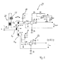
- FIG. 2 shows the circuit diagram according to FIG. 1 with a additional circuit for compensation of Offset output voltage of the operational amplifiers OP1, OP2. Out For reasons of clarity, the additional circuit only for the upper one Monitoring circuit 24 in the template according to FIG. 1 located. However, a similar circuit is also for the lower one in the graphic representation Monitoring circuit 26 is provided.
Landscapes
- Engineering & Computer Science (AREA)
- Mechanical Engineering (AREA)
- Train Traffic Observation, Control, And Security (AREA)
- Traffic Control Systems (AREA)
- Dc Digital Transmission (AREA)
Abstract
Description
- Figur 1
- ein Prinzipschaltbild eines Stromabgriffs an einem Lampenstromkreis eines Eisenbahnsignals; und
- Figur 2
- das Prinzipschaltbild gemäss Figur 1 mit einer zusätzlichen Schaltung zur Kompensation der Offsetausgangsspannung.
- 20
- Lampenstromkreis
- 22
- Signallampe
- 24, 26
- Überwachungsstromkreis
- 28, 30
- Stromeinkoppelpfade
- AS1, AS2
- Analog-Switches
- C1 bis C3
- Kapazitäten
- IP
- primärseitiger Strom
- Iein1, Iein2
- Eingangsstrom
- IR3, IR13
- Gegenkoppelstrom
- K
- transformatorische Kopplung
- KP
- Primärseite
- KS1, KS2
- Sekundärseite
- N1, N2, N3
- Windungszahl
- OP1 bis OP3
- Operationsverstärker
- R1 bis R13
- Widerstände
- Uein1, Uein2
- Eingangsspannung
- Uout1, Uout2
- Ausgangsspannung
- UP
- Versorgungsspannung
Claims (11)
- Vorrichtung zur Überwachung und/oder Regelung von schienengebundenem Verkehr, bei der eine transformatorische Kopplung (K) und zugleich eine galvanische Trennung zwischen einem Signalstromkreis (20), insbesondere einem Stromkreis (20) eines Signalleuchtmittels (22), und einem Überwachungsstromkreis (24, 26) vorgesehen sind, wobei die Windungszahl N1 der Primärwicklung (KP) des Signalstromkreises (20) kleiner als die Windungszahl N2 der Sekundärwicklung (KS1, KS2) des Überwachungsstromkreises (24, 26) ist und die Sekundärwicklung (KS1, KS2) an ein Mittel (OP1, OP2) angeschlossen ist, das die Sekundärwicklung (KS1, KS2) zumindest annähernd kurzschlussbeschaltet und ein dem Stromfluss (IP) im Signalstromkreis (20) entsprechendes Ausgangssignal (Uout1, Uout2) liefert.
- Vorrichtung nach Anspruch 1,
dadurch gekennzeichnet, dass
die Windungszahl N1 der Primärwicklung (KP) nicht grösser als 5 ist und die Windungszahl N2 der Sekundärwicklung (KS1, KS2) 50 nicht unterschreitet. - Vorrichtung nach Anspruch 2,
dadurch gekennzeichnet, dass
N1 = 1 un N2 = 150 sind. - Vorrichtung nach einem der Ansprüche 1 bis 3,
dadurch gekennzeichnet, dass
das Mittel eine stromgesteuerte Spannungsquelle ist, bei der ein im Überwachungsstromkreis (24, 26) fliessender Strom (Iein1, Iein2) über einen Gegenkopplungswiderstand (R3, R13) abfliesst. - Vorrichtung nach Anspruch 4,
dadurch gekennzeichnet, dass
die Sekundärwicklung (KS1, KS2) an den Eingang eines Operationsverstärkers (OP1, OP2) angeschlossen ist und der Ausgang des Operationsverstärkers (OP1, OP2) über den Rückkopplungswiderstand (R3, R13) auf einen Ast des Eingangs des Operationsverstärkers (OP1, OP2) geschaltet ist. - Vorrichtung nach einem der Ansprüche 1 bis 5,
dadurch gekennzeichnet, dass
am Überwachungsstromkreis (24, 26) eine Spannung (Uout1, Uout2) abgreifbar ist, die proportional zu dem im Signalstromkreis (20) fliessenden Strom (Ip) ist. - Vorrichtung nach Anspruch 6,
dadurch gekennzeichnet, dass
die Spannung (Uout1, Uout2) am Ausgang eines invertierten Operationsverstärkers (OP1, OP2) abnehmbar ist. - Vorrichtung nach Anspruch 6 oder 7,
dadurch gekennzeichnet, dass
Mittel (OP3) vorgesehen sind, die zur Begrenzung des Eingangsoffsetstroms am Eingang des Operationsverstärkers (OP1, OP2) angeschlossen sind. - Vorrichtung nach Anspruch 8,
dadurch gekennzeichnet, dass
die Mittel eine aktive Eingangsoffsetstromkompensation mit einem weiteren Operationsverstärker (OP3) sind. - Vorrichtung nach einem der Ansprüche 1 bis 9,
dadurch gekennzeichnet, dass
der Flächeninhalt des Überwachungsstromkreises (24, 26) weniger als 2 cm2, vorzugsweise weniger als 1 cm2, beträgt. - Vorrichtung nach einem der Ansprüche 1 bis 10,
dadurch gekennzeichnet, dass
der Überwachungsstromkreis (24, 26) zweikanalig ausgebildet ist.
Priority Applications (6)
| Application Number | Priority Date | Filing Date | Title |
|---|---|---|---|
| DE50109448T DE50109448D1 (de) | 2001-10-11 | 2001-10-11 | Vorrichtung zur Überwachung und/oder Regelung von schienengebundenen Verkehr |
| AT01124191T ATE322415T1 (de) | 2001-10-11 | 2001-10-11 | Vorrichtung zur überwachung und/oder regelung von schienengebundenen verkehr |
| PT01124191T PT1304274E (pt) | 2001-10-11 | 2001-10-11 | Dispositivo de monitorizacao e/ou de regulacao do trafego ferroviario |
| ES01124191T ES2261315T3 (es) | 2001-10-11 | 2001-10-11 | Dispositivo para la vigilancia y/o regulacion del trafico sobre carriles. |
| EP01124191A EP1304274B1 (de) | 2001-10-11 | 2001-10-11 | Vorrichtung zur Überwachung und/oder Regelung von schienengebundenen Verkehr |
| DK01124191T DK1304274T3 (da) | 2001-10-11 | 2001-10-11 | Indretning til overvågning og/eller regulering af jernbanetrafik |
Applications Claiming Priority (1)
| Application Number | Priority Date | Filing Date | Title |
|---|---|---|---|
| EP01124191A EP1304274B1 (de) | 2001-10-11 | 2001-10-11 | Vorrichtung zur Überwachung und/oder Regelung von schienengebundenen Verkehr |
Publications (2)
| Publication Number | Publication Date |
|---|---|
| EP1304274A1 true EP1304274A1 (de) | 2003-04-23 |
| EP1304274B1 EP1304274B1 (de) | 2006-04-05 |
Family
ID=8178915
Family Applications (1)
| Application Number | Title | Priority Date | Filing Date |
|---|---|---|---|
| EP01124191A Expired - Lifetime EP1304274B1 (de) | 2001-10-11 | 2001-10-11 | Vorrichtung zur Überwachung und/oder Regelung von schienengebundenen Verkehr |
Country Status (6)
| Country | Link |
|---|---|
| EP (1) | EP1304274B1 (de) |
| AT (1) | ATE322415T1 (de) |
| DE (1) | DE50109448D1 (de) |
| DK (1) | DK1304274T3 (de) |
| ES (1) | ES2261315T3 (de) |
| PT (1) | PT1304274E (de) |
Cited By (2)
| Publication number | Priority date | Publication date | Assignee | Title |
|---|---|---|---|---|
| DE102004057449B3 (de) * | 2004-11-24 | 2006-07-20 | Siemens Ag | Schaltung zur Ansteuerung und Überwachung einer Mehrzahl von Signallampen |
| EP1721805A1 (de) * | 2005-04-11 | 2006-11-15 | Alcatel | Schaltungsanordnung zur Stromschwellwerterkennung |
Citations (3)
| Publication number | Priority date | Publication date | Assignee | Title |
|---|---|---|---|---|
| GB2029616A (en) * | 1978-09-04 | 1980-03-19 | Philips Nv | Electrical load monitoring arrangement |
| DE3145744C1 (de) * | 1981-11-19 | 1983-04-07 | Standard Elektrik Lorenz Ag, 7000 Stuttgart | Schaltungsanordnung zur Überwachung von Wechselstromverbrauchern, insbesondere Signallampen |
| DE3140559A1 (de) * | 1981-10-13 | 1983-04-28 | Standard Elektrik Lorenz Ag, 7000 Stuttgart | Schaltungsanordnung zum signaltechnisch sicheren betrieb von signallampen |
-
2001
- 2001-10-11 ES ES01124191T patent/ES2261315T3/es not_active Expired - Lifetime
- 2001-10-11 DK DK01124191T patent/DK1304274T3/da active
- 2001-10-11 PT PT01124191T patent/PT1304274E/pt unknown
- 2001-10-11 DE DE50109448T patent/DE50109448D1/de not_active Expired - Lifetime
- 2001-10-11 EP EP01124191A patent/EP1304274B1/de not_active Expired - Lifetime
- 2001-10-11 AT AT01124191T patent/ATE322415T1/de active
Patent Citations (3)
| Publication number | Priority date | Publication date | Assignee | Title |
|---|---|---|---|---|
| GB2029616A (en) * | 1978-09-04 | 1980-03-19 | Philips Nv | Electrical load monitoring arrangement |
| DE3140559A1 (de) * | 1981-10-13 | 1983-04-28 | Standard Elektrik Lorenz Ag, 7000 Stuttgart | Schaltungsanordnung zum signaltechnisch sicheren betrieb von signallampen |
| DE3145744C1 (de) * | 1981-11-19 | 1983-04-07 | Standard Elektrik Lorenz Ag, 7000 Stuttgart | Schaltungsanordnung zur Überwachung von Wechselstromverbrauchern, insbesondere Signallampen |
Cited By (2)
| Publication number | Priority date | Publication date | Assignee | Title |
|---|---|---|---|---|
| DE102004057449B3 (de) * | 2004-11-24 | 2006-07-20 | Siemens Ag | Schaltung zur Ansteuerung und Überwachung einer Mehrzahl von Signallampen |
| EP1721805A1 (de) * | 2005-04-11 | 2006-11-15 | Alcatel | Schaltungsanordnung zur Stromschwellwerterkennung |
Also Published As
| Publication number | Publication date |
|---|---|
| PT1304274E (pt) | 2006-06-30 |
| DE50109448D1 (de) | 2006-05-18 |
| ES2261315T3 (es) | 2006-11-16 |
| ATE322415T1 (de) | 2006-04-15 |
| DK1304274T3 (da) | 2006-08-14 |
| EP1304274B1 (de) | 2006-04-05 |
Similar Documents
| Publication | Publication Date | Title |
|---|---|---|
| DE29506883U1 (de) | Stromsensor nach dem Kompensationsprinzip | |
| DE112007001098T5 (de) | Datensignal-Isolationsvorrichtung | |
| DE3334548C2 (de) | ||
| EP2868548B1 (de) | Verfahren zur Überwachung eines Schaltungszustandes eines Schalters eines Zugsicherungssystem, sowie Zugsicherungssystem | |
| DE19709840C2 (de) | Einrichtung für die Achszählung zum Unterscheiden von Radbeeinflussungen und Nicht-Radbeeinflussungen | |
| DE202007019127U1 (de) | Vorrichtung zur Messung eines von einem Wechselstromanteil überlagerten Gleichstromanteils eines in Leitern von Wechselstrombahnen fließenden Stroms | |
| DE1605427C3 (de) | Schaltungsanordnung zum Erzeugen und Übertragen von Achszählimpulsen in Achszählanlagen | |
| EP1304274B1 (de) | Vorrichtung zur Überwachung und/oder Regelung von schienengebundenen Verkehr | |
| DE19957621C2 (de) | Anordnung zur Übertragung elektrischer Signale zwischen bewegten Teilen mit verringerter Wegezahl | |
| DE3046103C2 (de) | ||
| DE102017212730A1 (de) | Verfahren und Einrichtung zur Fehlerortung entlang einer Energieversorgungsstrecke bei Gleichstromsystemen | |
| DE2042573C3 (de) | Überwachungseinrichtung für ohmsche Verbraucher an Wechselspannung, vorzugsweise Signallampen für den Straßenverkehr | |
| DE2842966C2 (de) | Schaltung zur Überwachung der Steuerausgänge einer weiteren Schaltung | |
| DE3145744C1 (de) | Schaltungsanordnung zur Überwachung von Wechselstromverbrauchern, insbesondere Signallampen | |
| DE469386C (de) | Schaltung fuer selbsttaetige Streckenblockung | |
| DE19958080C1 (de) | Steuerbarer Bahnrückstromleiter | |
| DE2755046C2 (de) | Schaltungsanordnung für durch Gleisstromkreise überwachte Gleisabschnitte im Eisenbahnsicherungswesen | |
| DE4110990A1 (de) | Einrichtung zur pruefung von signallampen in eisenbahnanlagen | |
| DE3140559A1 (de) | Schaltungsanordnung zum signaltechnisch sicheren betrieb von signallampen | |
| DE1958922C3 (de) | Schaltungsanordnung für Achszählanlagen des Eisenbahnsicherungswesens | |
| DE10111156C1 (de) | Verfahren zur Reduktion von Gleis-und Erdströmen längs elektrisch betriebener Bahnstrecken | |
| DE1134103B (de) | Anordnung zum Vermeiden gegenseitiger stoerender Beeinflussung mehrerer elektromagnetischer Gleisgeraete im Eisenbahnsicherungswesen | |
| DE1119901B (de) | Einrichtung zur Anzeige des Fuellzustandes eines Gleises | |
| DE730680C (de) | Anordnung zur Fernuebertragung einer Mehrzahl von Kommandos | |
| DE3240516C2 (de) |
Legal Events
| Date | Code | Title | Description |
|---|---|---|---|
| PUAI | Public reference made under article 153(3) epc to a published international application that has entered the european phase |
Free format text: ORIGINAL CODE: 0009012 |
|
| AK | Designated contracting states |
Designated state(s): AT BE CH CY DE DK ES FI FR GB GR IE IT LI LU MC NL PT SE TR |
|
| AX | Request for extension of the european patent |
Extension state: AL LT LV MK RO SI |
|
| 17P | Request for examination filed |
Effective date: 20030602 |
|
| AKX | Designation fees paid |
Designated state(s): AT BE CH CY DE DK ES FI FR GB GR IE IT LI LU MC NL PT SE TR |
|
| GRAP | Despatch of communication of intention to grant a patent |
Free format text: ORIGINAL CODE: EPIDOSNIGR1 |
|
| GRAS | Grant fee paid |
Free format text: ORIGINAL CODE: EPIDOSNIGR3 |
|
| GRAA | (expected) grant |
Free format text: ORIGINAL CODE: 0009210 |
|
| AK | Designated contracting states |
Kind code of ref document: B1 Designated state(s): AT BE CH CY DE DK ES FI FR GB GR IE IT LI LU MC NL PT SE TR |
|
| PG25 | Lapsed in a contracting state [announced via postgrant information from national office to epo] |
Ref country code: IT Free format text: LAPSE BECAUSE OF FAILURE TO SUBMIT A TRANSLATION OF THE DESCRIPTION OR TO PAY THE FEE WITHIN THE PRESCRIBED TIME-LIMIT;WARNING: LAPSES OF ITALIAN PATENTS WITH EFFECTIVE DATE BEFORE 2007 MAY HAVE OCCURRED AT ANY TIME BEFORE 2007. THE CORRECT EFFECTIVE DATE MAY BE DIFFERENT FROM THE ONE RECORDED. Effective date: 20060405 |
|
| REG | Reference to a national code |
Ref country code: GB Ref legal event code: FG4D Free format text: NOT ENGLISH |
|
| REG | Reference to a national code |
Ref country code: CH Ref legal event code: EP |
|
| REG | Reference to a national code |
Ref country code: IE Ref legal event code: FG4D Free format text: LANGUAGE OF EP DOCUMENT: GERMAN |
|
| REF | Corresponds to: |
Ref document number: 50109448 Country of ref document: DE Date of ref document: 20060518 Kind code of ref document: P |
|
| GBT | Gb: translation of ep patent filed (gb section 77(6)(a)/1977) |
Effective date: 20060503 |
|
| REG | Reference to a national code |
Ref country code: PT Ref legal event code: SC4A Effective date: 20060421 |
|
| REG | Reference to a national code |
Ref country code: SE Ref legal event code: TRGR |
|
| REG | Reference to a national code |
Ref country code: DK Ref legal event code: T3 |
|
| PG25 | Lapsed in a contracting state [announced via postgrant information from national office to epo] |
Ref country code: MC Free format text: LAPSE BECAUSE OF NON-PAYMENT OF DUE FEES Effective date: 20061031 |
|
| ET | Fr: translation filed | ||
| REG | Reference to a national code |
Ref country code: ES Ref legal event code: FG2A Ref document number: 2261315 Country of ref document: ES Kind code of ref document: T3 |
|
| PLBE | No opposition filed within time limit |
Free format text: ORIGINAL CODE: 0009261 |
|
| STAA | Information on the status of an ep patent application or granted ep patent |
Free format text: STATUS: NO OPPOSITION FILED WITHIN TIME LIMIT |
|
| 26N | No opposition filed |
Effective date: 20070108 |
|
| PG25 | Lapsed in a contracting state [announced via postgrant information from national office to epo] |
Ref country code: GR Free format text: LAPSE BECAUSE OF FAILURE TO SUBMIT A TRANSLATION OF THE DESCRIPTION OR TO PAY THE FEE WITHIN THE PRESCRIBED TIME-LIMIT Effective date: 20060706 |
|
| PG25 | Lapsed in a contracting state [announced via postgrant information from national office to epo] |
Ref country code: TR Free format text: LAPSE BECAUSE OF FAILURE TO SUBMIT A TRANSLATION OF THE DESCRIPTION OR TO PAY THE FEE WITHIN THE PRESCRIBED TIME-LIMIT Effective date: 20060405 Ref country code: LU Free format text: LAPSE BECAUSE OF NON-PAYMENT OF DUE FEES Effective date: 20061011 |
|
| PG25 | Lapsed in a contracting state [announced via postgrant information from national office to epo] |
Ref country code: CY Free format text: LAPSE BECAUSE OF FAILURE TO SUBMIT A TRANSLATION OF THE DESCRIPTION OR TO PAY THE FEE WITHIN THE PRESCRIBED TIME-LIMIT Effective date: 20060405 |
|
| REG | Reference to a national code |
Ref country code: CH Ref legal event code: PCOW Free format text: SIEMENS SCHWEIZ AG;FREILAGERSTRASSE 40;8047 ZUERICH (CH) |
|
| PGFP | Annual fee paid to national office [announced via postgrant information from national office to epo] |
Ref country code: PT Payment date: 20100923 Year of fee payment: 10 Ref country code: IE Payment date: 20101021 Year of fee payment: 10 |
|
| PGFP | Annual fee paid to national office [announced via postgrant information from national office to epo] |
Ref country code: SE Payment date: 20101014 Year of fee payment: 10 |
|
| REG | Reference to a national code |
Ref country code: PT Ref legal event code: MM4A Free format text: LAPSE DUE TO NON-PAYMENT OF FEES Effective date: 20120411 |
|
| REG | Reference to a national code |
Ref country code: SE Ref legal event code: EUG |
|
| REG | Reference to a national code |
Ref country code: IE Ref legal event code: MM4A |
|
| PG25 | Lapsed in a contracting state [announced via postgrant information from national office to epo] |
Ref country code: PT Free format text: LAPSE BECAUSE OF NON-PAYMENT OF DUE FEES Effective date: 20120411 |
|
| PG25 | Lapsed in a contracting state [announced via postgrant information from national office to epo] |
Ref country code: IE Free format text: LAPSE BECAUSE OF NON-PAYMENT OF DUE FEES Effective date: 20111011 Ref country code: SE Free format text: LAPSE BECAUSE OF NON-PAYMENT OF DUE FEES Effective date: 20111012 |
|
| PGFP | Annual fee paid to national office [announced via postgrant information from national office to epo] |
Ref country code: FR Payment date: 20131015 Year of fee payment: 13 Ref country code: GB Payment date: 20131014 Year of fee payment: 13 |
|
| PGFP | Annual fee paid to national office [announced via postgrant information from national office to epo] |
Ref country code: FI Payment date: 20131011 Year of fee payment: 13 Ref country code: IT Payment date: 20131029 Year of fee payment: 13 |
|
| GBPC | Gb: european patent ceased through non-payment of renewal fee |
Effective date: 20141011 |
|
| PG25 | Lapsed in a contracting state [announced via postgrant information from national office to epo] |
Ref country code: FI Free format text: LAPSE BECAUSE OF NON-PAYMENT OF DUE FEES Effective date: 20141011 Ref country code: GB Free format text: LAPSE BECAUSE OF NON-PAYMENT OF DUE FEES Effective date: 20141011 |
|
| REG | Reference to a national code |
Ref country code: FR Ref legal event code: ST Effective date: 20150630 |
|
| PG25 | Lapsed in a contracting state [announced via postgrant information from national office to epo] |
Ref country code: IT Free format text: LAPSE BECAUSE OF NON-PAYMENT OF DUE FEES Effective date: 20141011 Ref country code: FR Free format text: LAPSE BECAUSE OF NON-PAYMENT OF DUE FEES Effective date: 20141031 |
|
| PGFP | Annual fee paid to national office [announced via postgrant information from national office to epo] |
Ref country code: DK Payment date: 20151021 Year of fee payment: 15 |
|
| REG | Reference to a national code |
Ref country code: DK Ref legal event code: EBP Effective date: 20161031 |
|
| PG25 | Lapsed in a contracting state [announced via postgrant information from national office to epo] |
Ref country code: DK Free format text: LAPSE BECAUSE OF NON-PAYMENT OF DUE FEES Effective date: 20161031 |
|
| PGFP | Annual fee paid to national office [announced via postgrant information from national office to epo] |
Ref country code: DE Payment date: 20171219 Year of fee payment: 17 |
|
| PGFP | Annual fee paid to national office [announced via postgrant information from national office to epo] |
Ref country code: BE Payment date: 20171019 Year of fee payment: 17 Ref country code: NL Payment date: 20171019 Year of fee payment: 17 Ref country code: AT Payment date: 20170907 Year of fee payment: 17 |
|
| PGFP | Annual fee paid to national office [announced via postgrant information from national office to epo] |
Ref country code: ES Payment date: 20180125 Year of fee payment: 17 Ref country code: CH Payment date: 20180103 Year of fee payment: 17 |
|
| REG | Reference to a national code |
Ref country code: DE Ref legal event code: R119 Ref document number: 50109448 Country of ref document: DE |
|
| REG | Reference to a national code |
Ref country code: CH Ref legal event code: PL |
|
| REG | Reference to a national code |
Ref country code: NL Ref legal event code: MM Effective date: 20181101 |
|
| REG | Reference to a national code |
Ref country code: AT Ref legal event code: MM01 Ref document number: 322415 Country of ref document: AT Kind code of ref document: T Effective date: 20181011 |
|
| REG | Reference to a national code |
Ref country code: BE Ref legal event code: MM Effective date: 20181031 |
|
| PG25 | Lapsed in a contracting state [announced via postgrant information from national office to epo] |
Ref country code: NL Free format text: LAPSE BECAUSE OF NON-PAYMENT OF DUE FEES Effective date: 20181101 Ref country code: DE Free format text: LAPSE BECAUSE OF NON-PAYMENT OF DUE FEES Effective date: 20190501 |
|
| PG25 | Lapsed in a contracting state [announced via postgrant information from national office to epo] |
Ref country code: LI Free format text: LAPSE BECAUSE OF NON-PAYMENT OF DUE FEES Effective date: 20181031 Ref country code: BE Free format text: LAPSE BECAUSE OF NON-PAYMENT OF DUE FEES Effective date: 20181031 Ref country code: CH Free format text: LAPSE BECAUSE OF NON-PAYMENT OF DUE FEES Effective date: 20181031 |
|
| PG25 | Lapsed in a contracting state [announced via postgrant information from national office to epo] |
Ref country code: AT Free format text: LAPSE BECAUSE OF NON-PAYMENT OF DUE FEES Effective date: 20181011 |
|
| REG | Reference to a national code |
Ref country code: ES Ref legal event code: FD2A Effective date: 20191129 |
|
| PG25 | Lapsed in a contracting state [announced via postgrant information from national office to epo] |
Ref country code: ES Free format text: LAPSE BECAUSE OF NON-PAYMENT OF DUE FEES Effective date: 20181012 |