EP1304183A1 - Mecanisme de refroidissement de moule pour moulage sous pression - Google Patents
Mecanisme de refroidissement de moule pour moulage sous pression Download PDFInfo
- Publication number
- EP1304183A1 EP1304183A1 EP01947790A EP01947790A EP1304183A1 EP 1304183 A1 EP1304183 A1 EP 1304183A1 EP 01947790 A EP01947790 A EP 01947790A EP 01947790 A EP01947790 A EP 01947790A EP 1304183 A1 EP1304183 A1 EP 1304183A1
- Authority
- EP
- European Patent Office
- Prior art keywords
- coolant
- cooling
- die
- passages
- metal mold
- Prior art date
- Legal status (The legal status is an assumption and is not a legal conclusion. Google has not performed a legal analysis and makes no representation as to the accuracy of the status listed.)
- Withdrawn
Links
- 238000001816 cooling Methods 0.000 title claims abstract description 82
- 239000002826 coolant Substances 0.000 claims abstract description 152
- 239000002184 metal Substances 0.000 claims abstract description 34
- 238000004512 die casting Methods 0.000 claims abstract description 21
- 238000000638 solvent extraction Methods 0.000 claims description 31
- 238000004891 communication Methods 0.000 description 10
- 239000000498 cooling water Substances 0.000 description 9
- 238000012856 packing Methods 0.000 description 8
- 238000010276 construction Methods 0.000 description 4
- 230000015572 biosynthetic process Effects 0.000 description 3
- 238000000034 method Methods 0.000 description 3
- 238000009835 boiling Methods 0.000 description 2
- 239000012530 fluid Substances 0.000 description 2
- 238000003754 machining Methods 0.000 description 2
- 230000002093 peripheral effect Effects 0.000 description 2
- XLYOFNOQVPJJNP-UHFFFAOYSA-N water Substances O XLYOFNOQVPJJNP-UHFFFAOYSA-N 0.000 description 2
- 238000003466 welding Methods 0.000 description 2
- 238000009825 accumulation Methods 0.000 description 1
- 230000007812 deficiency Effects 0.000 description 1
- 230000008021 deposition Effects 0.000 description 1
- 238000005553 drilling Methods 0.000 description 1
- 238000010892 electric spark Methods 0.000 description 1
- 238000012986 modification Methods 0.000 description 1
- 230000004048 modification Effects 0.000 description 1
- 238000010791 quenching Methods 0.000 description 1
- 230000000171 quenching effect Effects 0.000 description 1
- 238000007789 sealing Methods 0.000 description 1
- 230000000153 supplemental effect Effects 0.000 description 1
Images


Classifications
-
- B—PERFORMING OPERATIONS; TRANSPORTING
- B22—CASTING; POWDER METALLURGY
- B22D—CASTING OF METALS; CASTING OF OTHER SUBSTANCES BY THE SAME PROCESSES OR DEVICES
- B22D17/00—Pressure die casting or injection die casting, i.e. casting in which the metal is forced into a mould under high pressure
- B22D17/20—Accessories: Details
- B22D17/22—Dies; Die plates; Die supports; Cooling equipment for dies; Accessories for loosening and ejecting castings from dies
- B22D17/2218—Cooling or heating equipment for dies
-
- B—PERFORMING OPERATIONS; TRANSPORTING
- B22—CASTING; POWDER METALLURGY
- B22C—FOUNDRY MOULDING
- B22C9/00—Moulds or cores; Moulding processes
- B22C9/06—Permanent moulds for shaped castings
- B22C9/065—Cooling or heating equipment for moulds
Definitions
- the present invention relates to a cooling arrangement for a die-casting metal mold, and more particularly, to such a cooling arrangement capable of uniformly cooling the entirety of the die-casting metal mold.
- a conventional cooling arrangement for a die-casting metal mold is described in Laid-open Japanese Patent application Publication No.Sho-58-211405.
- a coolant passage is penetratingly formed in the metal mold.
- the passage has one open end connected to a coolant accumulation tank through a coolant inlet pipe, and has another open end connected to the tank through a coolant outlet pipe.
- a pump is provided at the coolant outlet pipe.
- the coolant in the tank is introduced into the coolant passage in the metal mold through the coolant inlet pipe, and is then circulated to the tank through the coolant outlet pipe.
- a temperature of the coolant in the tank is controlled by a tank temperature controller for supplying the coolant at its optimum temperature to the die-casting metal mold.
- Laid-open Japanese Patent Application Publication No. Hei-6-71408 discloses a method for forming a coolant passage in a die-casting metal mold. According to the disclosed method, a continuous deep groove is formed by a cut machining at a surface opposite to a mold cavity, and a lid is covered over the formed groove to provide a coolant passage. This method is designed to overcome the deficiency in a conventional drilling where a desirable configuration and orientation of the passage cannot be provided.
- a linear cooing bore 130 is bored from a surface opposite to a mold cavity 125 to a position adjacent to the mold cavity 125, and a coolant supply pipe 105 extends through and generally concentrically with the cooling bore 130.
- a coolant is supplied through the coolant supply pipe 105 in a direction indicated by an arrow in Fig. 7.
- the supplied coolant passes through a space defined between an inner peripheral surface of the cooling bore 130 and an outer peripheral surface of the coolant supply pipe 105, and is then discharged through a coolant discharge pipe 107.
- the metal mold can be locally cooled by a linear coolant passage extending in a depthwise direction (thickness direction) of the metal mold.
- a coolant adjacent to the coolant inlet has a low temperature
- a coolant adjacent to the coolant outlet has a high temperature, which cannot uniformly cool the entirety of the mold cavity at an even temperature.
- a region of the mold cavity and ambient region thereof cannot be uniformly cooled with the only one coolant passage. That is, it would be difficult to uniformly distribute the passage along the mold cavity due to a three dimensional construction of the mold cavity.
- the present invention provides a cooling arrangement 1 for cooling a die-casting metal mold 2 having a stationary die 24 and a movable die 22 defining a mold cavity 25 in combination with the stationary die 24, the cooling arrangement including coolant passage means formed in an interior of the die-casting metal mold 2 for allowing a coolant to pass therethrough for cooling the die-casing metal mold 2, the improvement wherein the coolant is made from an oil, and the coolant passage means comprises a plurality of coolant passages A,B,C,D,E,F,G formed at least in the movable die 22, and each of the coolant passages A,B,C,D,E,F,G is defined by a deep and wide groove 30,32,34,36,38 and a partitioning plate 31,33,35,37,39 disposed in the groove 30,32,34,36,38, each groove 30,32,34, 36,38 and each partitioning plate 31,33,35,37,39 having shapes in conformance with a shape of the mold cavity 25 and being
- the cooling arrangement for cooling the die-casting metal mold With the cooling arrangement for cooling the die-casting metal mold, clogging of the coolant passage with the fur can be prevented, and excessive lowering of the cooling performance due to boiling of the coolant can be avoided, since oil is used as the coolant. Further, an entire die-casting product can be uniformly cooled, since the coolant passage can be positioned close to the mold cavity and since the mold cavity surface can be uniformly cooled by supplying the coolant in an extensive region. As a result, shot cycle can be remarkably shortened. Further, difference in a temperature at or around the coolant supply circuit and a temperature at or around the coolant discharge circuit can be severely taken into consideration for attaining more uniform cooling to the mold product because of the formation of the plurality of coolant passages.
- the plurality of coolant passages A,B,C,D,E are grouped into a plurality of groups (A,B,C, D) and (E,F,G), and necessary numbers of the temperature controllers 9,10 are provided in accordance with the numbers of the groups to provide, for each group, a coolant circulation circuit 3,4 including a coolant supply circuit 5,6 and a coolant discharge circuit 7,8 with the associated temperature controller 9,10, whereby cooling control is performed independent of each group (A,B,C,D) and (E,F,G).
- the plurality of the coolant passages are grouped into a plurality of groups, and the temperature controllers are provided in correspondence to the groups, and the coolant circulation circuit constituted by the coolant supply circuit and the coolant discharge circuit is provided in association with the temperature controller for controlling cooling independent of each group. Therefore, a desired portion of the metal mold can be cooled, and control to the temperature of the coolant and control to the supply of the coolant can be performed independently of each group. Consequently, more precise cooling control can be achieved.
- the partitioning plate 31,33,35 37,39 has an outer surface formed with at least one auxiliary path 31e, 31f, 31g, 33e, 33f at a position adjacent to the mold cavity 25 to provide a branch flow of the coolant in the coolant passage A,B,C,D,E,F,G.
- the cooling oil can be distributed to wider area by the formation of the auxiliary path to further promote uniform cooling.
- the auxiliary path can be easily provided by forming a groove at the outer surface of the partitioning plate.
- FIG. 1 is a schematic view showing the cooling arrangement according to the embodiment.
- a die-casting metal mold 2 includes a movable die 22 fixed to a movable holder 21, and a stationary die 24 fixed to a stationary holder 23.
- a mold cavity 25 is defined at confronting surfaces of the movable die 22 and the stationary die 24.
- ejection pins 26a, 26b, 26c, 26d, 26e, 26f, 26g, 26h, 26i are provided at the movable die 22 for ejecting a mold product from the metal mold 2.
- a set of a plurality of coolant passages A, B, C, D are formed in the movable die 22, and another set of a plurality of coolant passages E, F, G are formed in the stationary die 24.
- oil is introduced as a coolant for cooling the metal mold 2. Electric spark machining oil, quenching oil, and temperature control oil are preferable as cooling oil.
- the coolant passages A, B, C, D at the movable die 22 have inlet side passages a1, b1, c1, d1 and outlet side passages a2, b2, c2, d2.
- the inlet side passages a1, b1, c1, d1 are connected to an inlet side manifold 5B formed with a plurality of inlet holes.
- the inlet side manifold 5B is connected to a temperature controller 9 through a supply pipe 5A.
- the supply pipe 5A and the inlet side manifold 5B constitute a coolant supply circuit 5.
- the outlet side passages a2, b2, c2, d2 are connected to a discharge side manifold 7B formed with a plurality of discharge holes.
- the discharge side manifold 7B is connected to the temperature controller 9 through a discharge pipe 7A.
- the discharge manifold 7B and the discharge pipe 7A constitute a coolant discharge circuit 7.
- the coolant supply circuit 5 and the coolant discharge circuit 7 constitute a coolant circulation circuit 3.
- the temperature controller 9 is provided with ON/OFF switch 9a for turning ON and OFF an electric power, a temperature control dial 9b for setting a temperature of the cooling oil, and a temperature display 9c for displaying a temperature of the cooling oil.
- a cooling device 11 is connected to the temperature controller 9.
- the cooling device 10 includes a cooling water supply tube 11a, a cooling water discharge tube 11b, and a stop valve 11c disposed at the cooling water supply tube 11a. In the cooling device 10, the cooling water is supplied to the temperature controller 9 through the cooling water supply tube 11a for cooling the cooling oil accumulated in an oil tank (not shown) disposed interior of the temperature controller 9. Then, the cooling water is discharged outside through the discharge tube 11b.
- the stop valve 11c controls flow rate of the cooling water to be supplied to the temperature controller 9 by controlling opening degree of the valve.
- the cooling oil is cooled to a temperature set by the temperature control dial 9b. In the illustrated embodiment, the cooling oil is cooled to about 20 centigrades.
- the coolant passages E, F, G at the stationary die 24 have inlet side passages e1, f1, g1 and outlet side passages e2, f2, g2.
- the inlet side passages e1, f1, g1 are connected to an inlet side manifold 6B formed with a plurality of inlet holes.
- the inlet side manifold 6B is connected to a temperature controller 10 through a supply pipe 6A.
- the temperature controller 10 is exclusively used for the coolant passages E, F, G.
- the supply pipe 6A and the inlet side manifold 6B constitute a coolant supply circuit 6.
- the outlet side passages e2, f2, g2 are connected to a discharge side manifold 8B formed with a plurality of discharge holes.
- the discharge side manifold 8B is connected to the temperature controller 10 through a discharge pipe 8A.
- the discharge manifold 8B and the discharge pipe 8A constitute a coolant discharge circuit 8.
- the coolant supply circuit 6 and the coolant discharge circuit 8 constitute a coolant circulation circuit 4.
- An arrangement of the temperature controller 10 is the same as that of the temperature controller 9.
- An ON/OFF switch 10a, a temperature control dial 10b, and a temperature display 10c are similarly provided.
- a cooling device 12 similar to the cooling device 11 is provided.
- a cooling water supply tube 12a, a cooling water discharge tube 12b and a stop valve 12c are similarly provided.
- pumps (not shown) are provided at the respective coolant circulation circuits.
- the coolant passages A through G are grouped into two groups, and temperature controllers and coolant circulation circuits 3, 4 are also grouped into the equal number of groups, so that supply control and temperature control of the coolant is performed independently of each group.
- the cooling oil passes through the temperature controllers 9, 10 and the coolant supply circuit 5, 6 in which the cooling oil is flowed into a plurality of separate passages at the inlet side manifold 5B, 6B, and are supplied to the respective coolant passages A through G. Accordingly, predetermined portions of the metal mold 2 are cooled. Then, the cooling oil discharged from the respective coolant passages A through G is directed to the temperature controller 9, 10 through the coolant discharge circuits 7, 8, and is cooled by the cooling device 11, 12. Thereafter, the cooled coolant is again supplied to the coolant supply circuits 5, 6.
- Fig. 2 is a front view of the movable die 22 of the metal mold 2 according to the present embodiment.
- broken lines indicate the coolant passages A through D formed in the movable die 22.
- coolant paths B1 and B2 are in fluid communication with each other to provide the coolant passage B.
- Each of the cooling passages A through D is defined by a deep groove having a sufficient width and a partitioning plate disposed within the groove. The groove and the partitioning plate have their shapes in conformance with the cavity shape and are positioned adjacent thereto.
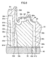
- Fig. 3 is a cross-sectional view taken along the line III-III of Fig. 2.
- the deep groove 30 is formed from a surface of the movable die 22 opposite to the surface at which the mold cavity 25 is provided.
- a cross-sectional shape of the deep groove 30 is defined by a vertical wall portions 30a, 30b extending generally in parallel with each other and a bottom wall portion 30c.
- a distance W between the vertical wall portions 30a and 30b is relatively large such as from 30 to 80 mm to render the groove 30 to be wide.
- the bottom wall portion 30c has a configuration in conformance with the contour of the mold cavity 25 such that a thickness t of the movable die 22 is approximately uniform along the bottom wall portion 30c to 3 mm. In other words, a distance between the mold cavity 25 and the bottom wall portion 30c is approximately 3 mm.
- the partitioning plate 31 is disposed in the deep groove 30.
- the partitioning plate 31 is welded to the movable die 22 such that the plate 31 is set from the surface of the movable die opposite to the surface of the mold cavity 25 as if a lid is covered over the groove 30.
- a cross-sectional shape of the partitioning plate 31 is in conformance with the shape of the vertical wall portions 30a, 30b and the bottom wall portion 30c of the groove 30. More specifically, the partitioning plate 31 has vertical wall portions 31a, 31b extending approximately in parallel with the vertical wall portions 30a, 30b of the groove 30, and has a tip end portion 31c extending approximately in parallel with the bottom wall portion 30c of the groove 30.
- a coolant path is defined at a space provided between the partitioning plate 31 and the groove 30.
- a space between the vertical walls 30a and 31a serves as a supply path A1
- a space between the bottom walls 30c and 31c serves as a main coolant path A3 for cooling a metal mold part adjacent to the mold cavity 25, and the space between the vertical walls 30b and 31b serves as discharge path A2.
- a pair of contact surfaces 31d, 31d defining a major outer contour of the partitioning plate 31 are in close contact with the vertical wall 30a, 30b of the groove 30.
- the contact surfaces 31d extend in the extending direction of the vertical walls 31a, 31b and are oriented approximately perpendicular to the vertical walls 31a, 31b for defining the supply path A1 and the discharge path A2.
- the contact surfaces 31d, 31d are formed with auxiliary paths 31e, 31f, 31g communicating the supply path A1 with the discharge path A2.
- These auxiliary paths 31e, 31f, 31g can be provided by forming three grooves at the respective contacting surfaces 31d, 31d of the partitioning plate 31 as shown in Figs. 3 and 4.
- a loop like fluid paths surrounding the partitioning plate 31 can be provided by the supply path A1, the discharge path A2 and the auxiliary paths 31e, 31f, 31g.
- these auxiliary paths 31e, 31f, 31g are positioned only adjacent to the surface of the cavity 25.
- the coolant passage A is branched into a plurality of paths adjacent to the mold cavity 25. Therefore, the portion in the vicinity of the surface of the cavity 25 can be more uniformly cooled, because coolant also passes through the auxiliary paths 31e, 31f, 31g.
- a heat resistant packing 41 and a packing holder 40 are disposed at the surface of the movable die 22 opposite to the mold cavity 25 for hermetically sealing the coolant passage A.
- the packing 41 is formed with holes 41a, 41b at positions corresponding to open ends of the supply path A1 and the discharge path A2.
- the packing holder 40 is formed with connection bores 40a, 40b each formed with a female thread at positions in alignment with the holes 41a, 41b, respectively.
- a combination of the supply path A1, the hole 41a and the connection bore 40a corresponds to the inlet side passage a1 shown in Fig. 1, and a combination of the discharge path A2, the hole 41b and the connection bores 40b corresponds to the outlet side passage a2 shown in Fig. 1.
- connection bore 40a is connected to the inlet side manifold 5B, and the connection bore 40b is connected to the outlet side manifold 7B.
- the welding portion of the partitioning plate 31 to the movable die 22 cannot be shown because the cross-sectional plane contains the connections bores 40a, 40b.
- the coolant passage B includes the coolant paths B1 and B2 as shown in Fig. 1.
- the coolant path B1 is defined by a deep groove 32 and a partitioning plate 33 disposed therein as shown in Fig. 5.
- the groove 32 has a bottom portion 32c whose shape is in conformance with the shape of the cavity 25, and the partitioning plate 33 has a tip end portion 33c whose shape is in conformance with the bottom portion 32c.
- a supply path B1a, a discharge path B1b and a main coolant path B1c are provided.
- the groove 32 has vertical wall portions 32a, 32b
- the partitioning plate 33 has vertical wall portions 33a, 33b.
- the partitioning plate 33 has contact surfaces 33d in close contact with the vertical wall portion of the groove 32, and auxiliary paths 33e, 33f are formed on the contact surfaces 33d similar to the auxiliary paths 31e, 31f, 31g.
- a communication path B1d in communication with the coolant path B2 is connected to the discharge path Bib of the coolant path B1.
- the communication path B1d is positioned near the surface opposite to the surface of the mold cavity 25, and is in the form of a shallow groove 32d independent of the shape of the mold cavity.
- a hole 41c in communication with the supply path B1a is formed in the packing 41, and a connection bore 40c formed with a female thread and in communication with the hole 41c is formed in the packing holder 40.
- a combination of the supply path B1a, the hole 41c and the connection bore 40c constitute the inlet side passage b1 shown in Fig. 1.
- the connection bore 40c is connected to the inlet side manifold 5B.
- the coolant path B2 is defined by a deep groove 34 and a partitioning plate 35 disposed therein.
- the groove 34 has a bottom portion 34c whose shape is in conformance with the shape of the cavity 25, and the partitioning plate 35 has a tip end portion 35c whose shape is in conformance with the bottom portion 34c.
- a supply path B2a, a discharge path B2b and a main coolant path B2c are provided.
- the supply path B2a is in communication with the communication path B1d, so that the coolant in the coolant path B1 is introduced into the coolant path B2.
- the groove 34 Similar to the coolant path B1, the groove 34 has vertical wall portions 34a, 34b, and the partitioning plate 35 has vertical wall portions 35a, 35b.
- the coolant path B2 has a supplemental cooling bore 34d along the surface of the cavity 25. Similar to the first coolant passage A, a hole 41d in communication with the discharge path B2b is formed in the packing 41, and a connection bore 40d formed with a female thread and in communication with the hole 41d is formed in the packing holder 40. A combination of the discharge path B2a, the hole 41d and the connection bore 40d constitute the outlet side passage b2 shown in Fig. 1. The connection bore 40d is connected to the outlet side manifold 7B.
- the coolant passages C and D are defined by deep grooves 36, 38 at which a thickness of the movable die 22 is about 3 mm, and partitioning plates 37, 39 disposed in the deep grooves 36, 38, respectively. With the grooves and the partitioning plates, supply paths C1, D1, discharge paths C2, D2 and main coolant paths (not shown) are provided. Further, the coolant passages E, F, G are defined in the stationary die 24 in arrangements similar to the cooling passage A formed in the movable die 22.
- the movable die 22 has four coolant passages A through D and the stationary die 24 has three coolant passages E through G.
- the numbers of the passages are not limited to these numbers, but optimum numbers and shape can be determined in accordance with the shape of the mold cavity.
- a group of the plurality of coolant passages A through D are formed in the movable die 22, and another group of the plurality of coolant passages E through G are formed in the stationary die 24.
- the coolant passage should at least be formed in the movable die. That is, the movable die generally has a complicated construction with a plurality of protrusions, whereas the stationary die generally has a plane like simple construction. If the stationary die has a plane like simple construction, the cooling to the portion of the mold cavity can be achieved by forming the coolant passage in the movable die only.
- a plurality of coolant passages are grouped into a plurality of groups, and a plurality of temperature controllers with the numbers equal to the numbers of the groups are provided.
- a circulation circuit including a coolant supply circuit 5 and a coolant discharge circuit 7 can be provided in connection with an associated temperature controller for each group.
- coolant temperature control and coolant supply control can be made in each group.
- the partitioning plates 31, 33, 35, 37, 39 disposed in the deep grooves 30, 32, 36, 38 are fixed to the die by welding.
- any fixing arrangement such as fixing with bolts and force-fitting are available.
- auxiliary paths 31e, 31f, 31g are formed in the partitioning plate 31, and two auxiliary path 33d, 33e are formed in the partitioning plate 33.
- the numbers of the auxiliary paths is not limited to these numbers, but at least one auxiliary path should be formed in the partitioning plate in order to enhance cooling performance.
- a cooling arrangement for cooling a die-casting metal mold according to the present invention is widely available in a case where uniform cooling to the entirety of the die-casting metal mold is required, or in a case where different cooling temperatures are required for different local parts of the metal mold.
Landscapes
- Engineering & Computer Science (AREA)
- Mechanical Engineering (AREA)
- Molds, Cores, And Manufacturing Methods Thereof (AREA)
- Moulds For Moulding Plastics Or The Like (AREA)
Applications Claiming Priority (3)
| Application Number | Priority Date | Filing Date | Title |
|---|---|---|---|
| JP2000195717 | 2000-06-29 | ||
| JP2000195717 | 2000-06-29 | ||
| PCT/JP2001/005611 WO2002000375A1 (fr) | 2000-06-29 | 2001-06-29 | Mecanisme de refroidissement de moule pour moulage sous pression |
Publications (2)
| Publication Number | Publication Date |
|---|---|
| EP1304183A1 true EP1304183A1 (fr) | 2003-04-23 |
| EP1304183A4 EP1304183A4 (fr) | 2005-12-21 |
Family
ID=18694332
Family Applications (1)
| Application Number | Title | Priority Date | Filing Date |
|---|---|---|---|
| EP01947790A Withdrawn EP1304183A4 (fr) | 2000-06-29 | 2001-06-29 | Mecanisme de refroidissement de moule pour moulage sous pression |
Country Status (5)
| Country | Link |
|---|---|
| US (1) | US6698496B2 (fr) |
| EP (1) | EP1304183A4 (fr) |
| JP (1) | JP3802873B2 (fr) |
| AU (1) | AU2001269427A1 (fr) |
| WO (1) | WO2002000375A1 (fr) |
Families Citing this family (22)
| Publication number | Priority date | Publication date | Assignee | Title |
|---|---|---|---|---|
| US7290587B2 (en) * | 2004-08-30 | 2007-11-06 | General Motors Corporation | Die thermal management through coolant flow control |
| JP2006198656A (ja) * | 2005-01-20 | 2006-08-03 | Hitachi Ltd | 金型冷却用マニホールド及びそれを用いた成形用金型装置 |
| JP5117077B2 (ja) * | 2006-03-17 | 2013-01-09 | 株式会社小出製作所 | 調温型 |
| US7421310B2 (en) * | 2006-06-12 | 2008-09-02 | Husky Injection Molding Systems Ltd. | Method and apparatus for controlling cooling rates during post-mold cooling of a molded article |
| JP5172131B2 (ja) * | 2006-11-01 | 2013-03-27 | Sabicイノベーティブプラスチックスジャパン合同会社 | 射出成形金型及び射出成形金型の製造方法並びに成形方法 |
| DE102007017690A1 (de) * | 2007-04-14 | 2008-10-16 | Siempelkamp Giesserei Gmbh | Verfahren und Vorrichtung zur Herstellung eines Gussteils |
| US7886807B2 (en) * | 2007-06-15 | 2011-02-15 | Die Therm Engineering L.L.C. | Die casting control method |
| US20090065170A1 (en) * | 2007-09-11 | 2009-03-12 | Honda Motor Co., Ltd. | Die cooling apparatus and method thereof |
| JP2009214166A (ja) * | 2008-03-12 | 2009-09-24 | Honda Motor Co Ltd | 多数個取り金型 |
| JP2012121245A (ja) * | 2010-12-09 | 2012-06-28 | Matsui Mfg Co | 金型冷却装置及びこれを備えた金型冷却システム |
| DE102011101957A1 (de) * | 2011-05-19 | 2012-11-22 | Audi Ag | Gussform zum Druckgießen eines Bauteils |
| TW201321157A (zh) * | 2011-11-17 | 2013-06-01 | Metal Ind Res Anddevelopment Ct | 模具及分區段調整模具冷卻效率的方法 |
| DE102014001563B4 (de) * | 2014-02-05 | 2015-08-20 | Universität Kassel | Gussform |
| US9744590B2 (en) | 2014-05-08 | 2017-08-29 | Honda Motor Co., Ltd. | Apparatus for injecting molten metal into a die cast machine and methods and control systems for cooling the same |
| CN106604791A (zh) * | 2014-09-08 | 2017-04-26 | 西门子公司 | 用于形成可用于燃气涡轮发动机中的部件的混合压铸系统 |
| CN105108111B (zh) * | 2015-08-27 | 2017-05-17 | 内蒙古兰太实业股份有限公司 | 铸钠成型设备 |
| EP3344408B1 (fr) * | 2015-09-02 | 2020-05-27 | Alfi S.R.L. | Système de refroidissement de moules pour métaux ou alliages métalliques, et ensemble de moulage comprenant ledit système de refroidissement et au moins un moule |
| WO2018148806A1 (fr) * | 2017-02-16 | 2018-08-23 | Billio Pty Ltd | Système de refroidissement pour moules |
| CN108262459A (zh) * | 2018-01-24 | 2018-07-10 | 宁波隆源精密机械有限公司 | 一种压铸模具的热节快速冷却结构 |
| CN110154348A (zh) * | 2019-06-10 | 2019-08-23 | 江苏民扬塑胶科技有限公司 | 一种节能降耗模温机 |
| CN110421139B (zh) * | 2019-08-30 | 2024-04-02 | 南通华东油压科技有限公司 | 一种后盖铸件定位成型模具及成型加工方法 |
| CN114871406B (zh) * | 2022-04-27 | 2024-09-17 | 广东鸿图科技股份有限公司 | 一种大型压铸模具温度精准控制方法 |
Citations (2)
| Publication number | Priority date | Publication date | Assignee | Title |
|---|---|---|---|---|
| JPH01143750A (ja) * | 1987-11-26 | 1989-06-06 | Ube Ind Ltd | 金型の温度制御方法 |
| JPH09155529A (ja) * | 1995-12-06 | 1997-06-17 | Toyota Motor Corp | 金型冷却構造 |
Family Cites Families (4)
| Publication number | Priority date | Publication date | Assignee | Title |
|---|---|---|---|---|
| US3973617A (en) * | 1975-04-28 | 1976-08-10 | Curtiss-Wright Corporation | Method and apparatus for cooling diecasting mold |
| JPS6427920A (en) | 1987-07-24 | 1989-01-30 | Mitsubishi Heavy Ind Ltd | Mold |
| JPH07185769A (ja) | 1993-12-28 | 1995-07-25 | Toyota Motor Corp | 金型装置 |
| US6312628B1 (en) * | 1998-12-28 | 2001-11-06 | Cito Products, Inc. | Mold temperature control |
-
2001
- 2001-06-29 AU AU2001269427A patent/AU2001269427A1/en not_active Abandoned
- 2001-06-29 WO PCT/JP2001/005611 patent/WO2002000375A1/fr not_active Application Discontinuation
- 2001-06-29 JP JP2002505145A patent/JP3802873B2/ja not_active Expired - Fee Related
- 2001-06-29 US US10/311,635 patent/US6698496B2/en not_active Expired - Fee Related
- 2001-06-29 EP EP01947790A patent/EP1304183A4/fr not_active Withdrawn
Patent Citations (2)
| Publication number | Priority date | Publication date | Assignee | Title |
|---|---|---|---|---|
| JPH01143750A (ja) * | 1987-11-26 | 1989-06-06 | Ube Ind Ltd | 金型の温度制御方法 |
| JPH09155529A (ja) * | 1995-12-06 | 1997-06-17 | Toyota Motor Corp | 金型冷却構造 |
Non-Patent Citations (3)
| Title |
|---|
| PATENT ABSTRACTS OF JAPAN vol. 013, no. 400 (M-867), 6 September 1989 (1989-09-06) & JP 01 143750 A (UBE IND LTD), 6 June 1989 (1989-06-06) * |
| PATENT ABSTRACTS OF JAPAN vol. 1997, no. 10, 31 October 1997 (1997-10-31) & JP 09 155529 A (TOYOTA MOTOR CORP; GIFU SEIKI KOGYO KK), 17 June 1997 (1997-06-17) * |
| See also references of WO0200375A1 * |
Also Published As
| Publication number | Publication date |
|---|---|
| US20030168199A1 (en) | 2003-09-11 |
| US6698496B2 (en) | 2004-03-02 |
| WO2002000375A1 (fr) | 2002-01-03 |
| JP3802873B2 (ja) | 2006-07-26 |
| AU2001269427A1 (en) | 2002-01-08 |
| EP1304183A4 (fr) | 2005-12-21 |
Similar Documents
| Publication | Publication Date | Title |
|---|---|---|
| EP1304183A1 (fr) | Mecanisme de refroidissement de moule pour moulage sous pression | |
| JP6445007B2 (ja) | 操作性を向上するための非メルト内部チャンネルを有するホットランナマニホルドを備えた射出成形システム | |
| CN104105843B (zh) | 在高热应力构件中产生近表面冷却通道的方法和有此通道的构件 | |
| CZ286349B6 (cs) | Způsob výroby temperovaných nástrojů, případně forem pro výrobu součástí z plastické hmoty a tímto způsobem vyrobené temperované nástroje, případně formy | |
| JP2007125894A (ja) | ブロー成形用金型装置 | |
| US6598451B2 (en) | Internally cooled tool pack | |
| US6742571B2 (en) | Build-up mold for continuous casting | |
| US11311928B2 (en) | Hot press machine | |
| US20130160966A1 (en) | Die cast part of a die casting mold and corresponding die casting device | |
| JP7095546B2 (ja) | 成形装置 | |
| JP4177219B2 (ja) | 冷却機能付き金型 | |
| WO1997015434A1 (fr) | Systeme de moulage de produits en materiau thermoplastique et utilisation de ce systeme dans un appareil d'extrusion-soufflage | |
| TWI831812B (zh) | 用於豎爐的冷卻盒 | |
| US20080041552A1 (en) | Single-piece cooling blocks for casting and molding | |
| US9248496B2 (en) | Die cast part of a die casting mold and corresponding die casting device | |
| EP1234624A2 (fr) | Ensemble distributeur pour le moulage de noyaux | |
| JPH11211023A (ja) | ノズルマニホールド | |
| US20200238362A1 (en) | Hot press machine | |
| JP2000042712A (ja) | 内冷構造付き金型 | |
| US11897175B2 (en) | Mold plate cooling arrangement | |
| CN219096451U (zh) | 一种流体控制组件 | |
| WO2014133702A1 (fr) | Canal chauffant et éléments de celui-ci comprenant une zone de conditionnement de matière fondue | |
| KR20230112169A (ko) | 조립식 냉각 채널을 가지는 금형 제조방법 및 조립식 냉각 채널을 가지는 금형 | |
| JP7147586B2 (ja) | 熱間プレス加工装置 | |
| KR100450641B1 (ko) | 마이크로 금형용 공정온도 제어시스템이 구비된 금형장치 |
Legal Events
| Date | Code | Title | Description |
|---|---|---|---|
| PUAI | Public reference made under article 153(3) epc to a published international application that has entered the european phase |
Free format text: ORIGINAL CODE: 0009012 |
|
| 17P | Request for examination filed |
Effective date: 20030122 |
|
| AK | Designated contracting states |
Designated state(s): AT BE CH CY DE DK ES FI FR GB GR IE IT LI LU MC NL PT SE TR |
|
| AX | Request for extension of the european patent |
Extension state: AL LT LV MK RO SI |
|
| A4 | Supplementary search report drawn up and despatched |
Effective date: 20051107 |
|
| GRAP | Despatch of communication of intention to grant a patent |
Free format text: ORIGINAL CODE: EPIDOSNIGR1 |
|
| STAA | Information on the status of an ep patent application or granted ep patent |
Free format text: STATUS: THE APPLICATION IS DEEMED TO BE WITHDRAWN |
|
| 18D | Application deemed to be withdrawn |
Effective date: 20070323 |