TECHNICAL FIELD
-
The present invention relates to a cooling arrangement
for a die-casting metal mold, and more particularly, to such
a cooling arrangement capable of uniformly cooling the entirety
of the die-casting metal mold.
BACKGROUND ART
-
A conventional cooling arrangement for a die-casting
metal mold is described in Laid-open Japanese Patent application
Publication No.Sho-58-211405. In the disclosed arrangement,
a coolant passage is penetratingly formed in the
metal mold. The passage has one open end connected to a
coolant accumulation tank through a coolant inlet pipe, and
has another open end connected to the tank through a coolant
outlet pipe. A pump is provided at the coolant outlet pipe.
Upon actuation of the pump, the coolant in the tank is introduced
into the coolant passage in the metal mold through
the coolant inlet pipe, and is then circulated to the tank
through the coolant outlet pipe. A temperature of the coolant
in the tank is controlled by a tank temperature controller
for supplying the coolant at its optimum temperature to
the die-casting metal mold.
-
Laid-open Japanese Patent Application Publication No.
Hei-6-71408 discloses a method for forming a coolant passage
in a die-casting metal mold. According to the disclosed
method, a continuous deep groove is formed by a cut machining
at a surface opposite to a mold cavity, and a lid is
covered over the formed groove to provide a coolant passage.
This method is designed to overcome the deficiency in a conventional
drilling where a desirable configuration and orientation
of the passage cannot be provided.
-
Further, still another conventional cooling arrangement
is shown in Fig. 7 in which a linear cooing bore 130 is
bored from a surface opposite to a mold cavity 125 to a position
adjacent to the mold cavity 125, and a coolant supply
pipe 105 extends through and generally concentrically with
the cooling bore 130. A coolant is supplied through the
coolant supply pipe 105 in a direction indicated by an arrow
in Fig. 7. The supplied coolant passes through a space defined
between an inner peripheral surface of the cooling
bore 130 and an outer peripheral surface of the coolant supply
pipe 105, and is then discharged through a coolant discharge
pipe 107. Thus, the metal mold can be locally cooled
by a linear coolant passage extending in a depthwise direction
(thickness direction) of the metal mold.
-
However, in these conventional cooling arrangements,
water is generally employed as the coolant. In such a case,
clogging of the coolant passage may occur due to deposition
of fur on the coolant passage or cooling efficiency may be
excessively lowered due to boiling of the water, if the
coolant passage is located adjacent to the mold cavity. In
view of this reason, the coolant passage must be positioned
away from the mold cavity by a predetermined distance.
-
Further, if a cross-sectional area of the coolant passage
is insufficiently small, it would be impossible to cool
a wide range of the mold cavity simultaneously, and therefore,
it would be difficult to uniformly cool the entirety
of the mold cavity.
-
Furthermore, in a conventional cooling arrangement,
only one coolant passage is formed in the mold cavity. In
this connection, a coolant adjacent to the coolant inlet has
a low temperature, whereas a coolant adjacent to the coolant
outlet has a high temperature, which cannot uniformly cool
the entirety of the mold cavity at an even temperature.
Moreover, a region of the mold cavity and ambient region
thereof cannot be uniformly cooled with the only one coolant
passage. That is, it would be difficult to uniformly distribute
the passage along the mold cavity due to a three dimensional
construction of the mold cavity.
-
Therefore, it is an object of the present invention to
provide a cooling arrangement capable of uniformly cooling
an entire region of the die-casting metal mold.
DISCLOSURE OF INVENTION
-
In order to attain the object, the present invention
provides a cooling arrangement 1 for cooling a die-casting
metal mold 2 having a stationary die 24 and a movable die 22
defining a mold cavity 25 in combination with the stationary
die 24, the cooling arrangement including coolant passage
means formed in an interior of the die-casting metal mold 2
for allowing a coolant to pass therethrough for cooling the
die-casing metal mold 2, the improvement wherein the coolant
is made from an oil, and the coolant passage means comprises
a plurality of coolant passages A,B,C,D,E,F,G formed at
least in the movable die 22, and each of the coolant passages
A,B,C,D,E,F,G is defined by a deep and wide groove
30,32,34,36,38 and a partitioning plate 31,33,35,37,39 disposed
in the groove 30,32,34,36,38, each groove 30,32,34,
36,38 and each partitioning plate 31,33,35,37,39 having
shapes in conformance with a shape of the mold cavity 25 and
being positioned adjacent thereto, and a temperature controller
9,10 with a cooling device 11,12 is connected to
each coolant passage A,B,C,D,E,F,G.
-
With the cooling arrangement for cooling the die-casting
metal mold, clogging of the coolant passage with the
fur can be prevented, and excessive lowering of the cooling
performance due to boiling of the coolant can be avoided,
since oil is used as the coolant. Further, an entire die-casting
product can be uniformly cooled, since the coolant
passage can be positioned close to the mold cavity and since
the mold cavity surface can be uniformly cooled by supplying
the coolant in an extensive region. As a result, shot cycle
can be remarkably shortened. Further, difference in a temperature
at or around the coolant supply circuit and a temperature
at or around the coolant discharge circuit can be
severely taken into consideration for attaining more uniform
cooling to the mold product because of the formation of the
plurality of coolant passages.
-
Preferably, the plurality of coolant passages
A,B,C,D,E are grouped into a plurality of groups (A,B,C, D)
and (E,F,G), and necessary numbers of the temperature controllers
9,10 are provided in accordance with the numbers of
the groups to provide, for each group, a coolant circulation
circuit 3,4 including a coolant supply circuit 5,6 and a
coolant discharge circuit 7,8 with the associated temperature
controller 9,10, whereby cooling control is performed
independent of each group (A,B,C,D) and (E,F,G).
-
With the cooling arrangement for cooling the die-casting
metal mold, the plurality of the coolant passages
are grouped into a plurality of groups, and the temperature
controllers are provided in correspondence to the groups,
and the coolant circulation circuit constituted by the coolant
supply circuit and the coolant discharge circuit is provided
in association with the temperature controller for
controlling cooling independent of each group. Therefore, a
desired portion of the metal mold can be cooled, and control
to the temperature of the coolant and control to the supply
of the coolant can be performed independently of each group.
Consequently, more precise cooling control can be achieved.
-
Further, preferably, the partitioning plate 31,33,35
37,39 has an outer surface formed with at least one auxiliary
path 31e, 31f, 31g, 33e, 33f at a position adjacent to the
mold cavity 25 to provide a branch flow of the coolant in
the coolant passage A,B,C,D,E,F,G.
-
With the cooling arrangement for cooling the die-casting
metal mold, the cooling oil can be distributed to
wider area by the formation of the auxiliary path to further
promote uniform cooling. The auxiliary path can be easily
provided by forming a groove at the outer surface of the
partitioning plate.
BRIEF DESCRIPTION OF DRAWINGS
-
- Fig. 1 is a schematic view showing a cooling arrangement
for cooling a die-casting metal mold according to one
embodiment of the present invention;
- Fig. 2 is a front view showing a movable die provided
with the cooling arrangement according to the embodiment of
the present invention;
- Fig. 3 is a cross-sectional view taken along the line
III-III of Fig. 2;
- Fig. 4 is a cross-sectional view taken along the line
IV-IV of Fig. 1;
- Fig. 5 is a cross-sectional view taken along the line
V-V of Fig. 2;
- Fig. 6 is a cross-sectional view taken along the line
VI-VI of Fig. 2; and
- Fig. 7 is a cross-sectional view showing a conventional
cooling arrangement for cooling a die-casting metal
mold.
-
BEST MODE FOR CARRYING OUT THE INVENTION
-
A cooling arrangement for cooling a die-casting metal
mold according to one embodiment of the present invention
will be described with reference to Figs. 1 through 6. Fig.
1 is a schematic view showing the cooling arrangement according
to the embodiment.
-
A die-casting metal mold 2 includes a movable die 22
fixed to a movable holder 21, and a stationary die 24 fixed
to a stationary holder 23. A mold cavity 25 is defined at
confronting surfaces of the movable die 22 and the stationary
die 24. As shown in Fig. 2, ejection pins 26a, 26b, 26c,
26d, 26e, 26f, 26g, 26h, 26i are provided at the movable die
22 for ejecting a mold product from the metal mold 2. As described
later, a set of a plurality of coolant passages A, B,
C, D are formed in the movable die 22, and another set of a
plurality of coolant passages E, F, G are formed in the stationary
die 24. To these coolant passages A through G, oil
is introduced as a coolant for cooling the metal mold 2.
Electric spark machining oil, quenching oil, and temperature
control oil are preferable as cooling oil.
-
The coolant passages A, B, C, D at the movable die 22
have inlet side passages a1, b1, c1, d1 and outlet side passages
a2, b2, c2, d2. The inlet side passages a1, b1, c1, d1
are connected to an inlet side manifold 5B formed with a
plurality of inlet holes. The inlet side manifold 5B is connected
to a temperature controller 9 through a supply pipe
5A. The supply pipe 5A and the inlet side manifold 5B constitute
a coolant supply circuit 5. The outlet side passages
a2, b2, c2, d2 are connected to a discharge side manifold 7B
formed with a plurality of discharge holes. The discharge
side manifold 7B is connected to the temperature controller
9 through a discharge pipe 7A. The discharge manifold 7B and
the discharge pipe 7A constitute a coolant discharge circuit
7. The coolant supply circuit 5 and the coolant discharge
circuit 7 constitute a coolant circulation circuit 3.
-
The temperature controller 9 is provided with ON/OFF
switch 9a for turning ON and OFF an electric power, a temperature
control dial 9b for setting a temperature of the
cooling oil, and a temperature display 9c for displaying a
temperature of the cooling oil. Further, a cooling device 11
is connected to the temperature controller 9. The cooling
device 10 includes a cooling water supply tube 11a, a cooling
water discharge tube 11b, and a stop valve 11c disposed
at the cooling water supply tube 11a. In the cooling device
10, the cooling water is supplied to the temperature controller
9 through the cooling water supply tube 11a for
cooling the cooling oil accumulated in an oil tank (not
shown) disposed interior of the temperature controller 9.
Then, the cooling water is discharged outside through the
discharge tube 11b. The stop valve 11c controls flow rate of
the cooling water to be supplied to the temperature controller
9 by controlling opening degree of the valve. The cooling
oil is cooled to a temperature set by the temperature
control dial 9b. In the illustrated embodiment, the cooling
oil is cooled to about 20 centigrades.
-
The coolant passages E, F, G at the stationary die 24
have inlet side passages e1, f1, g1 and outlet side passages
e2, f2, g2. The inlet side passages e1, f1, g1 are connected
to an inlet side manifold 6B formed with a plurality of
inlet holes. The inlet side manifold 6B is connected to a
temperature controller 10 through a supply pipe 6A. The temperature
controller 10 is exclusively used for the coolant
passages E, F, G. The supply pipe 6A and the inlet side
manifold 6B constitute a coolant supply circuit 6. The outlet
side passages e2, f2, g2 are connected to a discharge
side manifold 8B formed with a plurality of discharge holes.
The discharge side manifold 8B is connected to the temperature
controller 10 through a discharge pipe 8A. The discharge
manifold 8B and the discharge pipe 8A constitute a
coolant discharge circuit 8. The coolant supply circuit 6
and the coolant discharge circuit 8 constitute a coolant
circulation circuit 4. An arrangement of the temperature
controller 10 is the same as that of the temperature controller
9. An ON/OFF switch 10a, a temperature control dial
10b, and a temperature display 10c are similarly provided.
Further, a cooling device 12 similar to the cooling device
11 is provided. A cooling water supply tube 12a, a cooling
water discharge tube 12b and a stop valve 12c are similarly
provided. For circulating the coolant through the coolant
circulation circuits 3 and 4, pumps (not shown) are provided
at the respective coolant circulation circuits.
-
In this way, in the depicted embodiment, the coolant
passages A through G are grouped into two groups, and temperature
controllers and coolant circulation circuits 3, 4
are also grouped into the equal number of groups, so that
supply control and temperature control of the coolant is
performed independently of each group.
-
Upon actuation of the pump (not shown) the cooling oil
passes through the temperature controllers 9, 10 and the
coolant supply circuit 5, 6 in which the cooling oil is
flowed into a plurality of separate passages at the inlet
side manifold 5B, 6B, and are supplied to the respective
coolant passages A through G. Accordingly, predetermined
portions of the metal mold 2 are cooled. Then, the cooling
oil discharged from the respective coolant passages A
through G is directed to the temperature controller 9, 10
through the coolant discharge circuits 7, 8, and is cooled
by the cooling device 11, 12. Thereafter, the cooled coolant
is again supplied to the coolant supply circuits 5, 6.
-
Next, the coolant passages A through D in the movable
die 22 will be described. Fig. 2 is a front view of the movable
die 22 of the metal mold 2 according to the present embodiment.
In Fig. 2, broken lines indicate the coolant passages
A through D formed in the movable die 22. Incidentally,
coolant paths B1 and B2 are in fluid communication with each
other to provide the coolant passage B. Each of the cooling
passages A through D is defined by a deep groove having a
sufficient width and a partitioning plate disposed within
the groove. The groove and the partitioning plate have their
shapes in conformance with the cavity shape and are positioned
adjacent thereto.
-
The coolant passage A will be described. Fig. 3 is a
cross-sectional view taken along the line III-III of Fig. 2.
The deep groove 30 is formed from a surface of the movable
die 22 opposite to the surface at which the mold cavity 25
is provided. In Fig. 3, a cross-sectional shape of the deep
groove 30 is defined by a vertical wall portions 30a, 30b
extending generally in parallel with each other and a bottom
wall portion 30c. A distance W between the vertical wall
portions 30a and 30b is relatively large such as from 30 to
80 mm to render the groove 30 to be wide. Further, the bottom
wall portion 30c has a configuration in conformance with
the contour of the mold cavity 25 such that a thickness t of
the movable die 22 is approximately uniform along the bottom
wall portion 30c to 3 mm. In other words, a distance between
the mold cavity 25 and the bottom wall portion 30c is approximately
3 mm.
-
The partitioning plate 31 is disposed in the deep
groove 30. The partitioning plate 31 is welded to the movable
die 22 such that the plate 31 is set from the surface
of the movable die opposite to the surface of the mold cavity
25 as if a lid is covered over the groove 30. A cross-sectional
shape of the partitioning plate 31 is in conformance
with the shape of the vertical wall portions 30a, 30b
and the bottom wall portion 30c of the groove 30. More specifically,
the partitioning plate 31 has vertical wall portions
31a, 31b extending approximately in parallel with the
vertical wall portions 30a, 30b of the groove 30, and has a
tip end portion 31c extending approximately in parallel with
the bottom wall portion 30c of the groove 30. As a result, a
coolant path is defined at a space provided between the partitioning
plate 31 and the groove 30. To be more specific, a
space between the vertical walls 30a and 31a serves as a
supply path A1, a space between the bottom walls 30c and 31c
serves as a main coolant path A3 for cooling a metal mold
part adjacent to the mold cavity 25, and the space between
the vertical walls 30b and 31b serves as discharge path A2.
-
As shown in Fig. 4, a pair of contact surfaces 31d,
31d defining a major outer contour of the partitioning plate
31 are in close contact with the vertical wall 30a, 30b of
the groove 30. The contact surfaces 31d extend in the extending
direction of the vertical walls 31a, 31b and are
oriented approximately perpendicular to the vertical walls
31a, 31b for defining the supply path A1 and the discharge
path A2. The contact surfaces 31d, 31d are formed with auxiliary
paths 31e, 31f, 31g communicating the supply path A1
with the discharge path A2. These auxiliary paths 31e, 31f,
31g can be provided by forming three grooves at the respective
contacting surfaces 31d, 31d of the partitioning plate
31 as shown in Figs. 3 and 4. Thus, a loop like fluid paths
surrounding the partitioning plate 31 can be provided by the
supply path A1, the discharge path A2 and the auxiliary
paths 31e, 31f, 31g. As shown in Fig. 3, these auxiliary
paths 31e, 31f, 31g are positioned only adjacent to the surface
of the cavity 25. With the formation of the auxiliary
paths 31e, 31f, 31g, the coolant passage A is branched into
a plurality of paths adjacent to the mold cavity 25. Therefore,
the portion in the vicinity of the surface of the cavity
25 can be more uniformly cooled, because coolant also
passes through the auxiliary paths 31e, 31f, 31g.
-
A heat resistant packing 41 and a packing holder 40
are disposed at the surface of the movable die 22 opposite
to the mold cavity 25 for hermetically sealing the coolant
passage A. The packing 41 is formed with holes 41a, 41b at
positions corresponding to open ends of the supply path A1
and the discharge path A2. The packing holder 40 is formed
with connection bores 40a, 40b each formed with a female
thread at positions in alignment with the holes 41a, 41b,
respectively. A combination of the supply path A1, the hole
41a and the connection bore 40a corresponds to the inlet
side passage a1 shown in Fig. 1, and a combination of the
discharge path A2, the hole 41b and the connection bores 40b
corresponds to the outlet side passage a2 shown in Fig. 1.
The connection bore 40a is connected to the inlet side manifold
5B, and the connection bore 40b is connected to the
outlet side manifold 7B. Incidentally, in Fig. 3, the welding
portion of the partitioning plate 31 to the movable die
22 cannot be shown because the cross-sectional plane contains
the connections bores 40a, 40b.
-
The coolant passage B will next be described. The
coolant passage B includes the coolant paths B1 and B2 as
shown in Fig. 1. The coolant path B1 is defined by a deep
groove 32 and a partitioning plate 33 disposed therein as
shown in Fig. 5. The groove 32 has a bottom portion 32c
whose shape is in conformance with the shape of the cavity
25, and the partitioning plate 33 has a tip end portion 33c
whose shape is in conformance with the bottom portion 32c.
Thus, a supply path B1a, a discharge path B1b and a main
coolant path B1c are provided. Similar to the coolant passage
A, the groove 32 has vertical wall portions 32a, 32b,
and the partitioning plate 33 has vertical wall portions 33a,
33b. The partitioning plate 33 has contact surfaces 33d in
close contact with the vertical wall portion of the groove
32, and auxiliary paths 33e, 33f are formed on the contact
surfaces 33d similar to the auxiliary paths 31e, 31f, 31g.
A communication path B1d in communication with the coolant
path B2 is connected to the discharge path Bib of the coolant
path B1. The communication path B1d is positioned near
the surface opposite to the surface of the mold cavity 25,
and is in the form of a shallow groove 32d independent of
the shape of the mold cavity. Similar to the first coolant
passage A, a hole 41c in communication with the supply path
B1a is formed in the packing 41, and a connection bore 40c
formed with a female thread and in communication with the
hole 41c is formed in the packing holder 40. A combination
of the supply path B1a, the hole 41c and the connection bore
40c constitute the inlet side passage b1 shown in Fig. 1.
The connection bore 40c is connected to the inlet side manifold
5B.
-
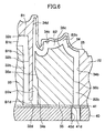
As shown in Fig. 6, the coolant path B2 is defined by
a deep groove 34 and a partitioning plate 35 disposed
therein. The groove 34 has a bottom portion 34c whose shape
is in conformance with the shape of the cavity 25, and the
partitioning plate 35 has a tip end portion 35c whose shape
is in conformance with the bottom portion 34c. Thus, a supply
path B2a, a discharge path B2b and a main coolant path
B2c are provided. The supply path B2a is in communication
with the communication path B1d, so that the coolant in the
coolant path B1 is introduced into the coolant path B2.
Similar to the coolant path B1, the groove 34 has vertical
wall portions 34a, 34b, and the partitioning plate 35 has
vertical wall portions 35a, 35b. In order to promote uniform
cooling, the coolant path B2 has a supplemental cooling bore
34d along the surface of the cavity 25. Similar to the first
coolant passage A, a hole 41d in communication with the discharge
path B2b is formed in the packing 41, and a connection
bore 40d formed with a female thread and in communication
with the hole 41d is formed in the packing holder 40. A
combination of the discharge path B2a, the hole 41d and the
connection bore 40d constitute the outlet side passage b2
shown in Fig. 1. The connection bore 40d is connected to the
outlet side manifold 7B.
-
As shown in Fig. 4, similar to the coolant passage A,
the coolant passages C and D are defined by deep grooves 36,
38 at which a thickness of the movable die 22 is about 3 mm,
and partitioning plates 37, 39 disposed in the deep grooves
36, 38, respectively. With the grooves and the partitioning
plates, supply paths C1, D1, discharge paths C2, D2 and main
coolant paths (not shown) are provided. Further, the coolant
passages E, F, G are defined in the stationary die 24 in
arrangements similar to the cooling passage A formed in the
movable die 22.
-
While the invention has been described in detail and
with reference to the specific embodiments thereof, it would
be apparent to those skilled in the art that various changes
and modifications may be made therein without departing from
the scope of the invention. For example, in the depicted embodiment,
the movable die 22 has four coolant passages A
through D and the stationary die 24 has three coolant passages
E through G. However, the numbers of the passages are
not limited to these numbers, but optimum numbers and shape
can be determined in accordance with the shape of the mold
cavity.
-
Further, in the depicted embodiment, a group of the
plurality of coolant passages A through D are formed in the
movable die 22, and another group of the plurality of coolant
passages E through G are formed in the stationary die 24.
However, the coolant passage should at least be formed in
the movable die. That is, the movable die generally has a
complicated construction with a plurality of protrusions,
whereas the stationary die generally has a plane like simple
construction. If the stationary die has a plane like simple
construction, the cooling to the portion of the mold cavity
can be achieved by forming the coolant passage in the movable
die only. In the latter case, a plurality of coolant
passages are grouped into a plurality of groups, and a plurality
of temperature controllers with the numbers equal to
the numbers of the groups are provided. Thus, a circulation
circuit including a coolant supply circuit 5 and a coolant
discharge circuit 7 can be provided in connection with an
associated temperature controller for each group. Thus,
coolant temperature control and coolant supply control can
be made in each group.
-
Further, in the depicted embodiment, the partitioning
plates 31, 33, 35, 37, 39 disposed in the deep grooves 30,
32, 36, 38 are fixed to the die by welding. However, any
fixing arrangement such as fixing with bolts and force-fitting
are available.
-
Further, in the depicted embodiment, three auxiliary
paths 31e, 31f, 31g are formed in the partitioning plate 31,
and two auxiliary path 33d, 33e are formed in the partitioning
plate 33. However, the numbers of the auxiliary paths is
not limited to these numbers, but at least one auxiliary
path should be formed in the partitioning plate in order to
enhance cooling performance.
INDUSTRIAL APPLIABILITY
-
A cooling arrangement for cooling a die-casting metal
mold according to the present invention is widely available
in a case where uniform cooling to the entirety of the die-casting
metal mold is required, or in a case where different
cooling temperatures are required for different local parts
of the metal mold.