EP1303885B1 - Leitfähiges verbundmaterial und aus diesem material mittels thermo-kompression geformte brennstoffzellenelektrode - Google Patents
Leitfähiges verbundmaterial und aus diesem material mittels thermo-kompression geformte brennstoffzellenelektrode Download PDFInfo
- Publication number
- EP1303885B1 EP1303885B1 EP01958157.8A EP01958157A EP1303885B1 EP 1303885 B1 EP1303885 B1 EP 1303885B1 EP 01958157 A EP01958157 A EP 01958157A EP 1303885 B1 EP1303885 B1 EP 1303885B1
- Authority
- EP
- European Patent Office
- Prior art keywords
- graphite
- clusters
- mixture
- electrode
- fuel cell
- Prior art date
- Legal status (The legal status is an assumption and is not a legal conclusion. Google has not performed a legal analysis and makes no representation as to the accuracy of the status listed.)
- Expired - Lifetime
Links
Images
Classifications
-
- H—ELECTRICITY
- H01—ELECTRIC ELEMENTS
- H01M—PROCESSES OR MEANS, e.g. BATTERIES, FOR THE DIRECT CONVERSION OF CHEMICAL ENERGY INTO ELECTRICAL ENERGY
- H01M4/00—Electrodes
- H01M4/86—Inert electrodes with catalytic activity, e.g. for fuel cells
- H01M4/96—Carbon-based electrodes
-
- H—ELECTRICITY
- H01—ELECTRIC ELEMENTS
- H01B—CABLES; CONDUCTORS; INSULATORS; SELECTION OF MATERIALS FOR THEIR CONDUCTIVE, INSULATING OR DIELECTRIC PROPERTIES
- H01B1/00—Conductors or conductive bodies characterised by the conductive materials; Selection of materials as conductors
- H01B1/20—Conductive material dispersed in non-conductive organic material
- H01B1/24—Conductive material dispersed in non-conductive organic material the conductive material comprising carbon-silicon compounds, carbon or silicon
-
- H—ELECTRICITY
- H01—ELECTRIC ELEMENTS
- H01M—PROCESSES OR MEANS, e.g. BATTERIES, FOR THE DIRECT CONVERSION OF CHEMICAL ENERGY INTO ELECTRICAL ENERGY
- H01M8/00—Fuel cells; Manufacture thereof
- H01M8/02—Details
- H01M8/0202—Collectors; Separators, e.g. bipolar separators; Interconnectors
- H01M8/023—Porous and characterised by the material
- H01M8/0234—Carbonaceous material
-
- H—ELECTRICITY
- H01—ELECTRIC ELEMENTS
- H01M—PROCESSES OR MEANS, e.g. BATTERIES, FOR THE DIRECT CONVERSION OF CHEMICAL ENERGY INTO ELECTRICAL ENERGY
- H01M8/00—Fuel cells; Manufacture thereof
- H01M8/02—Details
- H01M8/0202—Collectors; Separators, e.g. bipolar separators; Interconnectors
- H01M8/023—Porous and characterised by the material
- H01M8/0239—Organic resins; Organic polymers
-
- H—ELECTRICITY
- H01—ELECTRIC ELEMENTS
- H01M—PROCESSES OR MEANS, e.g. BATTERIES, FOR THE DIRECT CONVERSION OF CHEMICAL ENERGY INTO ELECTRICAL ENERGY
- H01M8/00—Fuel cells; Manufacture thereof
- H01M8/02—Details
- H01M8/0202—Collectors; Separators, e.g. bipolar separators; Interconnectors
- H01M8/023—Porous and characterised by the material
- H01M8/0241—Composites
- H01M8/0243—Composites in the form of mixtures
-
- Y—GENERAL TAGGING OF NEW TECHNOLOGICAL DEVELOPMENTS; GENERAL TAGGING OF CROSS-SECTIONAL TECHNOLOGIES SPANNING OVER SEVERAL SECTIONS OF THE IPC; TECHNICAL SUBJECTS COVERED BY FORMER USPC CROSS-REFERENCE ART COLLECTIONS [XRACs] AND DIGESTS
- Y02—TECHNOLOGIES OR APPLICATIONS FOR MITIGATION OR ADAPTATION AGAINST CLIMATE CHANGE
- Y02E—REDUCTION OF GREENHOUSE GAS [GHG] EMISSIONS, RELATED TO ENERGY GENERATION, TRANSMISSION OR DISTRIBUTION
- Y02E60/00—Enabling technologies; Technologies with a potential or indirect contribution to GHG emissions mitigation
- Y02E60/30—Hydrogen technology
- Y02E60/50—Fuel cells
-
- Y—GENERAL TAGGING OF NEW TECHNOLOGICAL DEVELOPMENTS; GENERAL TAGGING OF CROSS-SECTIONAL TECHNOLOGIES SPANNING OVER SEVERAL SECTIONS OF THE IPC; TECHNICAL SUBJECTS COVERED BY FORMER USPC CROSS-REFERENCE ART COLLECTIONS [XRACs] AND DIGESTS
- Y02—TECHNOLOGIES OR APPLICATIONS FOR MITIGATION OR ADAPTATION AGAINST CLIMATE CHANGE
- Y02P—CLIMATE CHANGE MITIGATION TECHNOLOGIES IN THE PRODUCTION OR PROCESSING OF GOODS
- Y02P70/00—Climate change mitigation technologies in the production process for final industrial or consumer products
- Y02P70/50—Manufacturing or production processes characterised by the final manufactured product
-
- Y—GENERAL TAGGING OF NEW TECHNOLOGICAL DEVELOPMENTS; GENERAL TAGGING OF CROSS-SECTIONAL TECHNOLOGIES SPANNING OVER SEVERAL SECTIONS OF THE IPC; TECHNICAL SUBJECTS COVERED BY FORMER USPC CROSS-REFERENCE ART COLLECTIONS [XRACs] AND DIGESTS
- Y10—TECHNICAL SUBJECTS COVERED BY FORMER USPC
- Y10T—TECHNICAL SUBJECTS COVERED BY FORMER US CLASSIFICATION
- Y10T428/00—Stock material or miscellaneous articles
- Y10T428/30—Self-sustaining carbon mass or layer with impregnant or other layer
Definitions
- the present invention relates to a conductive composite material and its method of manufacture. It also relates to a fuel cell electrode and a method of manufacturing such an electrode.
- the electrically conductive composite materials consist of conductive particles dispersed in an organic matrix.
- the electrical conduction threshold, or percolation threshold is reached when the conductive particles form a network of conductive paths connected over the entire volume of the composite material.
- the conductive particles may be metallic, which has the advantage of good electrical conductivity. However, they have the disadvantage of having a high density and being sensitive to the chemical environment of the battery. Non-metallic conductive particles are particularly interesting for their low density and for their chemical resistance.
- the most commonly used non-metallic conductive fillers are carbon-based powder products, such as carbon black or graphite powders and carbon fibers.
- the percolation threshold is reached for charge rates of a few% by volume for fibers and from 20% to 30% by volume for spheres. These charges typically make it possible to obtain conductivities in the volume of the material of the order of 10 -5 to 10 -1 S / cm. It can thus be seen that the conductivity of the composite materials is much lower than that of the feedstocks used (of the order of 1000 S / cm for graphite), even though the feed rates are higher than the percolation threshold. This effect is explained by the high contact resistance between adjacent particles.
- the covering surface of the charges is controlled by their geometry as well as their viscoelastic properties, that is to say their ability to deform under stress.
- the tunnel resistance is associated with any insulating film that can cover the surface of the particles. It may be adsorbed surfactants or more simply the organic matrix which coats the charges once they are dispersed therein. In this configuration, the conduction mechanism between conductive grains is no longer ohmic but is made by electronic jumps between isolated particles. Due to the low electron transport properties of polymers, the local electrical field between grains The conductors necessary to achieve the circulation of an electric current in all the conducting clusters constituted by the charges must be very important. Practically, the local electric field is never sufficient to allow an electronic jump between each particle connected but isolated by a polymer film. Only a small part of the conductive paths is solicited and actually participates in the flow of the current. Macroscopic conductivity is greatly reduced.
- the resistance at the interface between two particles is the sum of the constriction and tunneling resistances.
- tunnel resistance governs the macroscopic conductivity of heterogeneous media. Indeed, the tunnel resistance goes from 10 -8 to 10 3 ⁇ . cm when the thickness of the insulating film covering the conductive particles in contact varies from 0.5 to 12 nm. This insulation thickness of a few nanometers corresponds conventionally to the polymeric matrix layer adsorbed on the surface of the charges during the dispersion.
- bipolar separator plates In a complete assembly consisting of a series of electrochemical cells, these bipolar plates have the function of separating the anode and cathode electrodes, to allow the distribution of the hydrogen and oxygen gases, respectively at the cathode and the cathode. the anode, to collect the electric current produced and in some cases to allow the cooling of the cell.
- bipolar plates are made from machined graphite plates or stamped and non-corrodible metal plates (stainless steel or aluminum coated with titanium). Solutions employing machined graphite prove to be expensive and difficult to reconcile with mass production. Solutions using metal particles lead to relatively heavy plates.
- EP-A-0 774 337 discloses a process for manufacturing bodies molded by plastic extrusion loaded to more than 50% by volume (preferably between 65 and 90%) in conductive elements (lamellar graphite or not, conductive fibers ). Initially, the mixture of constituents is made in a kneader and, after having been crushed and crushed, the mixture is extruded in the form of a plate or a tube. The composite materials obtained are made from any type of conductive fillers available commercially.
- the document WO-A-96/12309 discloses the production of a stack for fuel cell, using a conductive composite material obtained by thermo-compressed mixture of lamellar graphite and fluorinated resin (PTFE).
- the composite material obtained by this method is non-porous and directly moldable by compression.
- the structure of the conductive composite material and the nature of the charges are not optimized to control the impermeability to gases and the cooling of the cell. It is necessary to deposit a barrier material on the surface to seal the assembly.
- the document EP-A-0 933 825 discloses a method for manufacturing repair plates for fuel cells based on a thermosetting binder (phenolic resin and epoxy) loaded with lamellar graphite or not.
- the mixture is thermo-compressed in a mold to the geometry of the separator plates to be produced.
- the porosity, and therefore in first approximation the gas impermeability, is optimized by promoting the evacuation of water and gases formed during the crosslinking.
- an insulating layer of resin covers the surface of the plates and must be stripped off.
- the document WO-A-98/53514 discloses a method of manufacturing by thermo-compression bipolar separator plates containing from 50 to 95% conductive fillers in different thermoplastics.
- the conductive fillers may be graphite, carbon black and carbon fibers.
- the problem of gas impermeability is circumvented by the addition of a hydrophilic agent promoting the migration of water into the pores of the material. This configuration mainly favors the evacuation of the water produced in the cell and allows the cooling of the cell.
- the document EP 0 935 303 A discloses a separator plate for a fuel cell.
- the separator plate has good gas impermeability. It is made of a material comprising lamellar graphite and a polymer which can be thermoplastic.
- the present invention has been designed to overcome the aforementioned drawbacks of conductive composite materials. It provides lightweight materials, very low surface resistance and optimized thermal conductivity in the direction parallel to the surface.
- a first object of the invention consists of a conductive composite material consisting of a high-pressure sintered mixture of lamellar graphite and thermoplastic polymer powder, the mixture optionally comprising a first type of lamellar graphite consisting of lamellae of particle size between 10 and 100 ⁇ m and a second type of lamellar graphite consisting of agglomerates of graphite particles bound and superimposed between them so that their main planes are parallel to each other, these agglomerates having a planar anisotropy and having between 10 ⁇ m and 1 mm of side and between 5 and 50 ⁇ m thick, the. mixture also comprising a thermoplastic polymer powder having a particle size of between 10 and 200 ⁇ m, the lamellae and / or agglomerates having their principal planes parallel to one another.
- the first type of lamellar graphite consists of lamellae with a particle size of between 20 and 50 ⁇ m.
- the agglomerates of the second type of lamellar graphite may consist of particles of 5 to 20 ⁇ m side and 0.1 to 5 microns thick.
- thermoplastic polymer powder has a particle size of less than 50 microns.
- This polymer may be fluorinated type, such as PVDF.
- the second type of lamellar graphite can be obtained by grinding, in the solid phase or in the solvent phase, followed by sieving, of graphite sheets, a said graphite sheet consisting of graphite particles whose main planes are parallel to the plane of said sheet.
- This grinding of graphite sheets may consist of grinding graphite sheets manufactured by calendering and / or rolling of natural or expanded graphite.
- the second type of lamellar graphite can also be obtained by grinding, in solid or liquid phase, a mass of graphite obtained by compression, grinding being followed by sieving.
- the drying step can be carried out by filtration of the solvent followed by degassing in a vacuum chamber.
- the shaping of the conductive composite material is carried out in a mold.
- the sintering can be carried out at a pressure of between 0.25 and 1 ton / cm 2 .
- a third object of the invention is constituted by a fuel cell electrode, comprising means for the circulation of a gaseous fluid on the surface of at least one of its main faces, obtained by high pressure sintering.
- a mixture of lamellar graphite and thermoplastic polymer powder possibly comprising a first type of lamellar graphite consisting of lamellae with a particle size of between 10 and 100 ⁇ m and a second type of lamellar graphite consisting of agglomerates of graphite particles bound together and superimposed between them so that their main planes are parallel to each other, these agglomerates having a planar anisotropy and having between 10 ⁇ m and 1 mm of side and between 5 and 50 ⁇ m of thickness, the mixture also comprising a thermoplastic polymer powder with a particle size of between 10 and 200 ⁇ m, the lamellae and / or agglomerates having their main planes parallel to each other and parallel to the main faces of the electrode.
- the first type of lamellar graphite may consist of lamellae with a particle size of between 20 and 50 ⁇ m.
- the agglomerates of the second type of lamellar graphite advantageously consist of particles having 5 to 20 ⁇ m side and 0.1 to 5 ⁇ m thick.
- the thermoplastic polymer powder may have a particle size less than 50 microns.
- the thermoplastic polymer is advantageously fluorinated type, for example PVDF.
- the means for the circulation of a gaseous fluid comprise flutes.
- the second type of lamellar graphite is obtained by grinding, in the solid phase or in the solvent phase, followed by sieving, of graphite sheets, a said graphite sheet consisting of graphite particles of which the main planes are parallel to the plane of said sheet.
- the grinding of graphite sheets may consist of grinding graphite sheets manufactured by calendering and / or rolling of natural or expanded graphite.
- the second type of lamellar graphite is obtained by grinding, in the solid or liquid phase, a mass of graphite obtained by compression, the grinding being followed by sieving.
- the drying step can be carried out by filtration of the solvent followed by degassing in a vacuum chamber.
- the sintering of the electrode can be carried out at a pressure of between 0.25 and 1 ton / cm 2 .
- the remainder of the description will relate to the production of a fuel cell electrode from a mixture comprising a first type of lamellar graphite and a second type of lamellar graphite.
- the first type of graphite has a particle size of between 10 and 100 ⁇ m. Preferably, the average particle size is 23 microns. Its specific surface is between 6 and 25 m 2 / g and its conductivity is of the order of 1000 S / cm. This type of graphite is available commercially.
- the second type of graphite may consist of particles from graphite sheets previously made by calendering expanded graphite.
- the density of leaves is 1.1.
- the permeability to helium of such sheets is 10 5 cm 2 / s / atm.
- the graphite sheets are ground in a solvent, or in a solid phase, to obtain agglomerates of graphite lamellae, these agglomerates having between 10 ⁇ m and 1 mm of side, with a majority of agglomerates between 100 and 300 ⁇ m on one side, and between 5 and 50 ⁇ m thick.
- the second type of graphite can also be obtained from exfoliated graphite platelets dispersed in an organic solvent.
- the graphite content in the solvent is between 10 and 50% by volume according to the dimensional characteristics of graphite (low dilution ratio for high surface area graphites, high platelets of a few m 2 / g of specific surface area) in order to obtain a paste of low viscosity.
- This mixture is stirred until a homogeneous dispersion.
- the paste is then dried by filtration of the solvent and then by degassing in a vacuum chamber. These operations may advantageously make it possible to recover the solvent.
- the dry pulp obtained consists of large agglomerates of graphite platelets, the platelets being mostly superimposed. In an agglomerate, platelets are superimposed, contiguous and their main planes are mostly parallel. This paste is then crushed and screened in order to obtain graphite agglomerates with a particle size of between 100 ⁇ m and 1 mm.
- the second type of graphite can still be obtained by grinding solid graphitic materials.
- the grinding is carried out in solid or liquid phase.
- the powder obtained is sieved to the particle size specified for the second type of graphite. It is preferable to use as raw material masses of graphite made by compression in order to have an anisotropic starting structure.
- the mixture also comprises a thermo-plastic polymer powder having a particle size of between 10 and 200 ⁇ m, preferably with a particle size of less than 50 ⁇ m.
- PVDF seems to be the most interesting polymer for the invention.
- the mixture may comprise by weight as much graphite of the first type as graphite of the second type.
- the graphite charge rate can be very high, between 70 and 85% by volume.
- the constituents of the mixture are previously dried and then mixed with the turbulence.
- the formulation is homogenized on a vibrating plate.
- the shaping of the conductive composite material can be done by means of a mold in which the mixture is sintered at high pressure.
- the mixture contained in the mold is brought to a temperature slightly lower than the melting point of the polymer (for example at 20 ° C. below the melting temperature). It is then gradually compressed to a pressure of between 0.25 and 1 ton / cm 2 . The temperature of the mixture is then raised slightly above the melting point of the polymer (for example 20 ° C above) for 10 minutes. The mixture is then cooled under pressure to a temperature of 40 ° C below the melting temperature of the polymer. The sintered mixture is then gradually brought to room temperature and ambient pressure.
- the pressure exerted on the mixture is uniaxial.
- the obtained material has a very anisotropic structure, the graphite lamellae orienting in a direction perpendicular to the pressing direction and the sintering operation does not involve the transport of material in the mold.
- This method makes it possible in particular to produce gas supply channels in fuel cell electrodes.
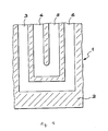
- the attached figure shows, in part, one of the main faces of a fuel cell electrode according to the present invention.
- the main face 2 of the electrode (or bipolar plate) 1 comprises splines 3, 4, 5 and 6 interconnected so as to allow the circulation of a gaseous fluid on the face 2 of the electrode.
- the conductive composite material according to the present invention has a strata structure, the lamellae or graphite agglomerates having their plane main parallel to major faces of the material formed into an electrode. This results in anisotropic electrical conductivity.
- This conductivity can vary from 1 to 30 S / cm in a direction transverse to the plane of the electrode (pressing direction) as a function of the rate of charge and the pressure during sintering. In a direction parallel to the plane of the electrode (that is to say a direction perpendicular to the pressing direction) the conductivity can vary between 50 and 200 S / cm.
- An electrode designed according to the present invention has an also anisotropic thermal conductivity. It is significantly greater in a direction parallel to the surface than in a transverse direction. In the case of a fuel cell electrode, this optimizes the cooling of the battery.
- the first type of graphite and the second type of graphite provide good surface conductivity and promote the cooling of an electrode.
- the second type of graphite makes it possible to obtain a very good impermeability to gases, especially helium and hydrogen.
- the gas permeability of the second type of graphite is lower than that of the graphite particles of the prior art.
- the large dimensions of the agglomerates constituting the second type of graphite (several hundred ⁇ m side) increase the tortuosity of the composite material.
Landscapes
- Chemical & Material Sciences (AREA)
- General Chemical & Material Sciences (AREA)
- Electrochemistry (AREA)
- Chemical Kinetics & Catalysis (AREA)
- Sustainable Energy (AREA)
- Life Sciences & Earth Sciences (AREA)
- Sustainable Development (AREA)
- Manufacturing & Machinery (AREA)
- Engineering & Computer Science (AREA)
- Physics & Mathematics (AREA)
- Dispersion Chemistry (AREA)
- Spectroscopy & Molecular Physics (AREA)
- Composite Materials (AREA)
- Fuel Cell (AREA)
- Compositions Of Macromolecular Compounds (AREA)
- Ceramic Products (AREA)
Claims (34)
- Leitfähiges Verbundmaterial aus einem mit hohem Druck gesinterten Gemisch von blättchenförmigem Graphit und einem Pulver eines thermoplastischen Polymers, dadurch gekennzeichnet, dass das Gemisch eine Art eines blättchenförmigen Graphits umfasst, die aus Agglomeraten von Graphitteilchen, die untereinander derart verbunden und überlagert sind, dass ihre Hauptflächen zueinander parallel sind, besteht, wobei diese Agglomerate eine Planaranisotropie aufweisen und eine Seitenlänge zwischen 10 µm und 1 mm und eine Dicke zwischen 5 und 50 µm aufweisen, wobei das Gemisch auch ein Pulver eines thermoplastischen Polymers einer Korngrößenverteilung zwischen 10 und 200 µm umfasst.
- Leitfähiges Verbundmaterial nach Anspruch 1, dadurch gekennzeichnet, dass das Gemisch ferner eine andere Art eines blättchenförmigen Graphits aufweist, die aus Blättchen einer Korngrößenverteilung zwischen 10 und 100 µm besteht, wobei die Blättchen und die Agglomerate zueinander parallele Hauptflächen aufweisen.
- Leitfähiges Verbundmaterial nach Anspruch 2, dadurch gekennzeichnet, dass die andere Art eines blättchenförmigen Graphits aus Blättchen einer Korngrößenverteilung zwischen 20 und 50 µm besteht.
- Leitfähiges Verbundmaterial nach einem der Ansprüche 1 bis 3, dadurch gekennzeichnet, dass die Agglomerate aus Teilchen einer Seitenlänge von 5 bis 20 µm und einer Dicke von 0,1 bis 5 µm bestehen.
- Leitfähiges Verbundmaterial nach einem der Ansprüche 1 bis 4, dadurch gekennzeichnet, dass das Pulver eines thermoplastischen Polymers eine geringere Korngrößenverteilung als 50 µm aufweist.
- Leitfähiges Verbundmaterial nach einem der Ansprüche 1 bis 5, dadurch gekennzeichnet, dass das thermoplastische Polymer ein fluoriertes ist.
- Leitfähiges Verbundmaterial nach Anspruch 6, dadurch gekennzeichnet, dass das thermoplastische Polymer ein PVDF ist.
- Verfahren zur Herstellung eines leitfähigen Verbundmaterials, dadurch gekennzeichnet, dass es umfasst:- Bereitstellen eines Gemischs, das ein Pulver eines thermoplastischen Polymers einer Korngrößenverteilung zwischen 10 und 200 µm, eine Art eines blättchenförmigen Graphits, die aus Agglomeraten von Graphitteilchen, die untereinander derart verbunden und überlagert sind, dass ihre Hauptflächen zueinander parallel sind, besteht, umfasst, wobei diese Agglomerate eine Planaranisotropie aufweisen und eine Seitenlänge zwischen 10 µm und 1 mm und eine Dicke zwischen 5 und 50 µm aufweisen,- Formen des leitfähigen Verbundmaterials durch Sintern des Gemischs unter hohem Druck, so dass die Hauptflächen der Agglomerate zueinander parallel sind.
- Verfahren nach Anspruch 8, dadurch gekennzeichnet, dass das Gemisch ferner eine andere Art eines blättchenförmigen Graphits, die aus Blättchen einer Korngrößenverteilung zwischen 10 und 100 µm besteht, umfasst, wobei die Stufe des Formens die Hauptflächen der Blättchen und der Agglomerate zueinander parallel anordnet.
- Verfahren nach Anspruch 9, dadurch gekennzeichnet, dass die Agglomerate durch Zerkleinern in einer Feststoffphase oder einer Lösemittelphase und ein nachfolgendes Sieben von Graphitblättern erhalten werden, wobei ein sogenanntes Graphitblatt aus Graphitteilchen besteht, deren Hauptflächen parallel zur Fläche des Blatts sind.
- Verfahren nach Anspruch 10, dadurch gekennzeichnet, dass das Zerkleinern von Graphitblättern darin besteht, Graphitblätter, die durch Kalandrieren und/oder Walzen von natürlichem oder expandiertem Graphit hergestellt wurden, zu mahlen.
- Verfahren nach Anspruch 8, dadurch gekennzeichnet, dass die Agglomerate durch Zerkleinern einer durch Kompression erhaltenen Graphitmasse im festen oder flüssigen Zustand erhalten werden, wobei auf das Zerkleinern ein Sieben folgt.
- Verfahren nach Anspruch 8, dadurch gekennzeichnet, dass die Agglomerate mittels der im Folgenden angegebenen Stufen erhalten werden:- Dispergieren von Graphitplättchen, die abgeschiefert oder durch Zerkleinern von Graphitblättern erhalten wurden, in einem organischen Lösemittel, bis eine homogene Paste erhalten wird,- Trocknen der erhaltenen homogenen Paste,- Grobzerkleinern der getrockneten Paste, um Agglomerate von Graphitteilchen zu erhalten,- Sieben der Agglomerate von Graphitteilchen.
- Verfahren nach Anspruch 13, dadurch gekennzeichnet, dass die Stufe des Trocknens durch Abfiltrieren vom Lösemittel und ein nachfolgendes Entgasen in einem Vakuumbehälter durchgeführt wird.
- Verfahren nach einem der Ansprüche 8 bis 14, dadurch gekennzeichnet, dass das Formen des leitfähigen Verbundmaterials in einer Form durchgeführt wird.
- Verfahren nach einem der Ansprüche 8 bis 15, dadurch gekennzeichnet, dass das Sintern mit einem Druck zwischen 0,25 und 1 t/cm2 durchgeführt wird.
- Verfahren nach einem der Ansprüche 8 bis 16, dadurch gekennzeichnet, dass das Sintern nach dem folgenden Zyklus durchgeführt wird:- das Gemisch wird auf eine Temperatur gebracht, die etwas unterhalb der Schmelztemperatur des thermoplastischen Polymers liegt,- das Gemisch wird schrittweise bis zu dem für das Sintern erforderlichen Druck komprimiert,- das komprimierte Gemisch wird über eine vorgegebene Zeitdauer auf eine Temperatur gebracht, die leicht oberhalb der Schmelztemperatur des thermoplastischen Polymers liegt,- das komprimierte Gemisch wird über eine vorgegebene Zeitdauer auf eine Temperatur gebracht, die unter der Schmelztemperatur des thermoplastischen Polymers liegt,- das gesinterte Gemisch wir schrittweise auf Umgebungstemperatur und Umgebungsdruck gebracht.
- Elektrode (1) für eine Brennstoffzelle, die Mittel (3, 4, 5, 6) umfasst, die die Zirkulation eines gasförmigen Fluids auf der Oberfläche von mindestens einer (2) von deren Hauptflächen ermöglichen, wobei die Elektrode durch Sintern eines Gemischs von blättchenförmigem Graphit und einem Pulver eines thermoplastischen Polymers mit hohem Druck erhalten wurde, wobei das Gemisch eine Art eines blättchenförmigen Graphits umfasst, die aus Agglomeraten von Graphitteilchen, die untereinander derart verbunden und überlagert sind, dass ihre Hauptflächen zueinander parallel sind, besteht, wobei diese Agglomerate eine Planaranisotropie aufweisen und eine Seitenlänge zwischen 10 µm und 1 mm und eine Dicke zwischen 5 und 50 µm aufweisen, wobei das Gemisch auch ein Pulver eines thermoplastischen Polymers einer Korngrößenverteilung zwischen 10 und 200 µm umfasst, wobei die Agglomerate Hauptflächen aufweisen, die untereinander und zu den Hauptflächen der Elektrode parallel sind.
- Elektrode (1) für eine Brennstoffzelle nach Anspruch 18, dadurch gekennzeichnet, dass das Gemisch ferner eine andere Art eines blättchenförmigen Graphits, die aus Blättchen einer Korngrößenverteilung zwischen 10 und 100 µm besteht, umfasst, wobei die Blättchen und die Agglomerate zueinander parallele Hauptflächen aufweisen.
- Elektrode (1) für eine Brennstoffzelle nach Anspruch 19, dadurch gekennzeichnet, dass die andere Art eines blättchenförmigen Graphits aus Blättchen einer Korngrößenverteilung zwischen 20 und 50 µm besteht.
- Elektrode (1) für eine Brennstoffzelle nach einem der Ansprüche 18 bis 20, dadurch gekennzeichnet, dass die Agglomerate aus Teilchen einer Seitenlänge von 5 bis 20 µm und einer Dicke von 0,1 bis 5 µm bestehen.
- Elektrode (1) für eine Brennstoffzelle nach einem der Ansprüche 18 bis 21, dadurch gekennzeichnet, dass das Pulver eines thermoplastischen Polymers eine geringere Korngrößenverteilung als 50 µm aufweist.
- Elektrode (1) für eine Brennstoffzelle nach einem der Ansprüche 18 bis 22, dadurch gekennzeichnet, dass das thermoplastische Polymer ein fluoriertes ist.
- Elektrode (1) für eine Brennstoffzelle nach Anspruch 23, dadurch gekennzeichnet, dass das thermoplastische Polymer ein PVDF ist.
- Elektrode (1) für eine Brennstoffzelle nach einem der Ansprüche 18 bis 24, dadurch gekennzeichnet, dass die Mittel, die die Zirkulation eines gasförmigen Fluids ermöglichen, Rillen (3, 4, 5, 6) umfassen.
- Verfahren zur Herstellung einer Elektrode (1) für eine Brennstoffzelle, die Mittel (3, 4, 5, 6) umfasst, die die Zirkulation eines gasförmigen Fluids an der Oberfläche von mindestens einer (2) von deren Hauptflächen ermöglichen, dadurch gekennzeichnet, dass das Verfahren umfasst:- Bereitstellen eines Gemischs, das ein Pulver eines thermoplastischen Polymers einer Korngrößenverteilung zwischen 10 und 200 µm und eine Art eines blättchenförmigen Graphits, die aus Agglomeraten von Graphitteilchen, die untereinander derart verbunden und überlagert sind, dass ihre Hauptflächen zueinander parallel sind, besteht, umfasst, wobei diese Agglomerate eine Planaranisotropie aufweisen und eine Seitenlänge zwischen 10 µm und 1 mm und eine Dicke zwischen 5 und 50 µm aufweisen,- Formen der Elektrode durch Sintern des Gemischs mit hohem Druck in einer Form, so dass die Hauptflächen der Agglomerate parallel zueinander und zu den Hauptflächen der Elektrode sind, wobei die Mittel, die die Zirkulation eines gasförmigen Fluids ermöglichen, während des Sinterns mit hohem Druck gebildet werden.
- Verfahren zur Herstellung einer Elektrode (1) für eine Brennstoffzelle nach Anspruch 26, dadurch gekennzeichnet, dass das Gemisch ferner eine andere Art eines blättchenförmigen Graphits, die aus Blättchen einer Korngrößenverteilung zwischen 10 und 100 µm besteht, umfasst, wobei die Blättchen und die Agglomerate ihre zueinander parallelen Hauptflächen infolge des Formens der Elektrode aufweisen.
- Verfahren zur Herstellung einer Elektrode (1) für eine Brennstoffzelle nach Anspruch 27, dadurch gekennzeichnet, dass die aus Agglomeraten bestehende Art eines blättchenförmigen Graphits durch Zerkleinern in einer Feststoffphase oder einer Lösemittelphase und nachfolgendes Sieben von Graphitblättern erhalten wird, wobei ein sogenanntes Graphitblatt aus Graphitteilchen besteht, deren Hauptflächen parallel zur Fläche des Blattes sind.
- Verfahren zur Herstellung einer Elektrode (1) für eine Brennstoffzelle nach Anspruch 28, dadurch gekennzeichnet, dass das Zerkleinern von Graphitblättern darin besteht, Graphitblätter, die durch Kalandrieren und/oder Walzen von natürlichem oder expandiertem Graphit hergestellt wurden, zu mahlen.
- Verfahren zur Herstellung einer Elektrode (1) für eine Brennstoffzelle nach Anspruch 26, dadurch gekennzeichnet, dass die aus Agglomeraten bestehende Art eines blättchenförmigen Graphits durch Zerkleinern einer durch Kompression erhaltenen Graphitmasse in flüssiger oder fester Phase erhalten wird, wobei auf das Zerkleinern ein Sieben folgt.
- Verfahren zur Herstellung einer Elektrode (1) für eine Brennstoffzelle nach Anspruch 26, dadurch gekennzeichnet, dass die aus Agglomeraten bestehende Art eines blättchenförmigen Graphits mittels der folgenden Stufen erhalten wird:- Dispergieren von Graphitplättchen, die abgeschiefert oder durch Zerkleinern von Graphitblättern erhalten wurden, in einem organischen Lösemittel, bis eine homogene Paste erhalten wird,- Trocknen der erhaltenen homogenen Paste,- Grobzerkleinern der getrockneten Paste, um Agglomerate von Graphitteilchen zu erhalten,- Sieben der Agglomerate von Graphitteilchen.
- Verfahren zur Herstellung einer Elektrode (1) für eine Brennstoffzelle nach Anspruch 31, dadurch gekennzeichnet, dass die Stufe des Trocknens durch Abfiltration vom Lösemittel und nachfolgendes Entgasen in einem Vakuumbehälter durchgeführt wird.
- Verfahren zur Herstellung einer Elektrode (1) für eine Brennstoffzelle nach einem der Ansprüche 26 bis 32, dadurch gekennzeichnet, dass das Sintern mit einem Druck zwischen 0,25 und 1 t/cm2 durchgeführt wird.
- Verfahren zur Herstellung einer Elektrode (1) für eine Brennstoffzelle nach einem der Ansprüche 26 bis 33, dadurch gekennzeichnet, dass das Sintern nach dem folgenden Zyklus durchgeführt wird:- das Gemisch wird auf eine Temperatur gebracht, die etwas unterhalb der Schmelztemperatur des thermoplastischen Polymers liegt,- das Gemisch wird schrittweise bis zu dem für das Sintern erforderlichen Druck komprimiert,- das komprimierte Gemisch wird über eine vorgegebene Zeitdauer auf eine Temperatur gebracht, die leicht oberhalb der Schmelztemperatur des thermoplastischen Polymers liegt,- das komprimierte Gemisch wird über eine vorgegebene Zeitdauer auf eine Temperatur gebracht, die unter der Schmelztemperatur des thermoplastischen Polymers liegt,- das gesinterte Gemisch wir schrittweise auf Umgebungstemperatur und Umgebungsdruck gebracht.
Applications Claiming Priority (3)
| Application Number | Priority Date | Filing Date | Title |
|---|---|---|---|
| FR0009666 | 2000-07-24 | ||
| FR0009666A FR2812119B1 (fr) | 2000-07-24 | 2000-07-24 | Materiau composite conducteur et electrode pour pile a combustible utilisant ce materiau mis en forme par thermo- compression |
| PCT/FR2001/002392 WO2002009219A1 (fr) | 2000-07-24 | 2001-07-23 | Materiau composite conducteur et electrode pour pile a combustible utilisant ce materiau mis en forme par thermo-compression |
Publications (2)
| Publication Number | Publication Date |
|---|---|
| EP1303885A1 EP1303885A1 (de) | 2003-04-23 |
| EP1303885B1 true EP1303885B1 (de) | 2014-06-11 |
Family
ID=8852836
Family Applications (1)
| Application Number | Title | Priority Date | Filing Date |
|---|---|---|---|
| EP01958157.8A Expired - Lifetime EP1303885B1 (de) | 2000-07-24 | 2001-07-23 | Leitfähiges verbundmaterial und aus diesem material mittels thermo-kompression geformte brennstoffzellenelektrode |
Country Status (8)
| Country | Link |
|---|---|
| US (1) | US7147960B2 (de) |
| EP (1) | EP1303885B1 (de) |
| JP (1) | JP4890724B2 (de) |
| CA (1) | CA2416892C (de) |
| DK (1) | DK1303885T3 (de) |
| ES (1) | ES2500290T3 (de) |
| FR (1) | FR2812119B1 (de) |
| WO (1) | WO2002009219A1 (de) |
Families Citing this family (15)
| Publication number | Priority date | Publication date | Assignee | Title |
|---|---|---|---|---|
| WO2003088395A1 (en) | 2002-04-17 | 2003-10-23 | Matsushita Electric Industrial Co., Ltd. | Polymeric electrolyte type fuel cell |
| US8501307B2 (en) * | 2007-09-04 | 2013-08-06 | Nanotek Instruments, Inc. | Recompressed exfoliated graphite articles |
| WO2009037926A1 (ja) * | 2007-09-18 | 2009-03-26 | Konica Minolta Medical & Graphic, Inc. | シンチレータパネル |
| CN103563140B (zh) | 2011-05-23 | 2015-11-25 | 株式会社Lg化学 | 具有增强的功率密度特性的高输出锂二次电池 |
| JP2014514726A (ja) * | 2011-05-23 | 2014-06-19 | エルジー ケム. エルティーディ. | エネルギー密度特性が向上した高エネルギー密度のリチウム二次電池 |
| WO2012161477A2 (ko) * | 2011-05-23 | 2012-11-29 | 주식회사 엘지화학 | 출력 밀도 특성이 향상된 고출력의 리튬 이차전지 |
| JP2014513409A (ja) * | 2011-05-23 | 2014-05-29 | エルジー ケム. エルティーディ. | 出力密度特性が向上した高出力のリチウム二次電池 |
| WO2012161474A2 (ko) | 2011-05-23 | 2012-11-29 | 주식회사 엘지화학 | 출력 밀도 특성이 향상된 고출력의 리튬 이차전지 |
| JP2014517459A (ja) * | 2011-05-23 | 2014-07-17 | エルジー ケム. エルティーディ. | エネルギー密度特性が向上した高エネルギー密度のリチウム二次電池 |
| JP2014523095A (ja) | 2011-07-13 | 2014-09-08 | エルジー・ケム・リミテッド | エネルギー密度特性が向上した高エネルギーのリチウム二次電池 |
| DE102013107514A1 (de) | 2013-07-16 | 2015-01-22 | Fraunhofer-Gesellschaft zur Förderung der angewandten Forschung e.V. | Verfahren zur Herstellung eines Verbundhalbzeugs |
| WO2015130281A1 (en) * | 2014-02-27 | 2015-09-03 | Clearedge Power, Llc | Fuel cell component including flake graphite |
| JP6741917B2 (ja) * | 2015-03-27 | 2020-08-19 | パナソニックIpマネジメント株式会社 | 燃料電池用触媒層及び燃料電池 |
| FR3100930B1 (fr) * | 2019-09-17 | 2021-09-17 | Commissariat Energie Atomique | Procédé de fabrication d’une électrode comprenant une matrice polymérique piégeant un électrolyte |
| CN114976096B (zh) * | 2022-04-20 | 2024-03-26 | 同济大学 | 一种燃料电池双极板用双树脂体系复合石墨及其制备方法和应用 |
Family Cites Families (33)
| Publication number | Priority date | Publication date | Assignee | Title |
|---|---|---|---|---|
| GB928351A (en) | 1958-07-04 | 1963-06-12 | South African Council Scientif | New or improved materials and moulded bodies of high electrical and thermal conductivity and high chemical resistance and a process for the manufacture thereof |
| GB991581A (en) * | 1962-03-21 | 1965-05-12 | High Temperature Materials Inc | Expanded pyrolytic graphite and process for producing the same |
| JPS56137503A (en) * | 1980-03-31 | 1981-10-27 | Pioneer Electronic Corp | Tone arm constituent |
| US4414142A (en) | 1980-04-18 | 1983-11-08 | Vogel F Lincoln | Organic matrix composites reinforced with intercalated graphite |
| JPS5942781A (ja) * | 1982-08-09 | 1984-03-09 | Tokai Carbon Co Ltd | 燃料電池用炭素質材の製造法 |
| US4704231A (en) * | 1984-05-21 | 1987-11-03 | Chung Deborah D L | Low-density graphite-polymer electrical conductors |
| US4680139A (en) | 1985-04-08 | 1987-07-14 | Ferro Corporation | Electrostatically conductive premold coating |
| JPH0642371B2 (ja) * | 1986-05-22 | 1994-06-01 | イビデン株式会社 | 燃料電池複合電極の製造方法 |
| US4758473A (en) * | 1986-11-20 | 1988-07-19 | Electric Power Research Institute, Inc. | Stable carbon-plastic electrodes and method of preparation thereof |
| JPH0813902B2 (ja) * | 1987-07-02 | 1996-02-14 | ライオン株式会社 | 導電性樹脂組成物 |
| US4988583A (en) * | 1989-08-30 | 1991-01-29 | Her Majesty The Queen As Represented By The Minister Of National Defence Of Her Majesty's Canadian Government | Novel fuel cell fluid flow field plate |
| US5176863A (en) * | 1991-08-06 | 1993-01-05 | Ucar Carbon Technology Corporation | Flexible graphite composite fire retardant wallpaper and method |
| US5286415A (en) * | 1992-12-28 | 1994-02-15 | Advanced Products, Inc. | Water-based polymer thick film conductive ink |
| US5558955A (en) * | 1994-10-07 | 1996-09-24 | International Fuel Cells Corporation | Cathode reactant flow field component for a fuel cell stack |
| JP4028890B2 (ja) | 1995-07-05 | 2007-12-26 | 日清紡績株式会社 | 固体高分子電解質型燃料電池用セパレータ及びその製造方法 |
| DE19542721A1 (de) | 1995-11-16 | 1997-05-22 | Sgl Technik Gmbh | Verfahren zur Herstellen von Formkörpern aus Kunststoff-Füllstoff-Mischungen mit einem hohen Gehalt an Füllstoffen |
| US5863467A (en) * | 1996-05-03 | 1999-01-26 | Advanced Ceramics Corporation | High thermal conductivity composite and method |
| JP3731255B2 (ja) * | 1996-07-18 | 2006-01-05 | トヨタ自動車株式会社 | 燃料電池用集電体の製造方法 |
| CA2266631A1 (en) * | 1997-07-28 | 1999-02-04 | Nisshinbo Industries Inc. | Separator for fuel cells |
| JP3455466B2 (ja) | 1998-04-07 | 2003-10-14 | 日立化成工業株式会社 | 燃料電池及び燃料電池用セパレータ |
| JP4707786B2 (ja) * | 1998-05-07 | 2011-06-22 | トヨタ自動車株式会社 | 燃料電池用ガスセパレータの製造方法 |
| JP2000058083A (ja) * | 1998-06-05 | 2000-02-25 | Nisshinbo Ind Inc | 燃料電池用セパレータ及びその製造方法 |
| JP3413368B2 (ja) | 1998-06-18 | 2003-06-03 | 日立化成工業株式会社 | 燃料電池、燃料電池用セパレータ及びその製造方法 |
| US6037074A (en) * | 1998-07-07 | 2000-03-14 | Ucar Carbon Technology Corporation | Flexible graphite composite for use in the form of a fuel cell flow field plate |
| JP3573444B2 (ja) * | 1998-07-24 | 2004-10-06 | 東海カーボン株式会社 | 固体高分子型燃料電池用炭素質セパレータ部材及びその製造方法 |
| JP3152226B2 (ja) | 1998-08-27 | 2001-04-03 | 日本電気株式会社 | 非水電解液二次電池、その製造法および炭素材料組成物 |
| JP4239250B2 (ja) * | 1998-09-18 | 2009-03-18 | 日立化成工業株式会社 | 黒鉛粒子の製造法、黒鉛粒子、黒鉛粒子を用いた黒鉛ペースト、リチウム二次電池用負極及びリチウム二次電池 |
| US6248467B1 (en) | 1998-10-23 | 2001-06-19 | The Regents Of The University Of California | Composite bipolar plate for electrochemical cells |
| US6180275B1 (en) | 1998-11-18 | 2001-01-30 | Energy Partners, L.C. | Fuel cell collector plate and method of fabrication |
| JP4028940B2 (ja) | 1998-12-17 | 2008-01-09 | 日清紡績株式会社 | 燃料電池セパレータ、その製造方法及び当該燃料電池セパレータを使用した固体高分子型燃料電池 |
| US6461755B1 (en) | 1999-06-09 | 2002-10-08 | Nisshinbo Industries, Inc. | Electroconductive resin composition, fuel cell separator made of said electroconductive resin composition, process for production of said fuel cell separator, and solid polymer type fuel cell using said fuel cell separator |
| US6413671B1 (en) * | 2000-04-10 | 2002-07-02 | Gaftech Inc. | Flexible graphite article and fuel cell electrode with enhanced electrical and thermal conductivity |
| FR2817076A1 (fr) * | 2000-11-20 | 2002-05-24 | Atofina | Poudre microcomposite a base d'un electroconducteur et d'un fluoropolymere et objets fabriques avec cette poudre |
-
2000
- 2000-07-24 FR FR0009666A patent/FR2812119B1/fr not_active Expired - Fee Related
-
2001
- 2001-07-23 EP EP01958157.8A patent/EP1303885B1/de not_active Expired - Lifetime
- 2001-07-23 JP JP2002514824A patent/JP4890724B2/ja not_active Expired - Fee Related
- 2001-07-23 WO PCT/FR2001/002392 patent/WO2002009219A1/fr not_active Ceased
- 2001-07-23 US US10/333,809 patent/US7147960B2/en not_active Expired - Lifetime
- 2001-07-23 DK DK01958157.8T patent/DK1303885T3/da active
- 2001-07-23 ES ES01958157.8T patent/ES2500290T3/es not_active Expired - Lifetime
- 2001-07-23 CA CA2416892A patent/CA2416892C/fr not_active Expired - Lifetime
Also Published As
| Publication number | Publication date |
|---|---|
| WO2002009219A1 (fr) | 2002-01-31 |
| US7147960B2 (en) | 2006-12-12 |
| JP4890724B2 (ja) | 2012-03-07 |
| EP1303885A1 (de) | 2003-04-23 |
| CA2416892C (fr) | 2010-04-13 |
| CA2416892A1 (fr) | 2002-01-31 |
| FR2812119B1 (fr) | 2002-12-13 |
| FR2812119A1 (fr) | 2002-01-25 |
| DK1303885T3 (da) | 2014-08-25 |
| JP2004505001A (ja) | 2004-02-19 |
| ES2500290T3 (es) | 2014-09-30 |
| US20040038116A1 (en) | 2004-02-26 |
Similar Documents
| Publication | Publication Date | Title |
|---|---|---|
| EP1303886B1 (de) | Brennstoffzellenelektrode verwendend leitfähiges verbundmaterial | |
| CA2416892C (fr) | Materiau composite conducteur et electrode pour pile a combustible utilisant ce materiau mis en forme par thermo-compression | |
| US20250300180A1 (en) | Compositions and methods for electrode fabrication | |
| EP1466372B1 (de) | Mikrozusammensetzungspulver auf der basis von flachen graphitpartikeln und eines fluorpolymers und daraus hergestellte objekte | |
| EP3108522B1 (de) | Verfahren zur herstellung einer elektrode oder zusammensetzung mit magnetischen eigenschaften und durch besagtes verfahren hergestellte mischung sowie besagte elektrode | |
| BE1008327A6 (fr) | Batterie bipolaire plomb-acide et procede de durcissement des plaques bipolaires a y utiliser. | |
| US7160615B2 (en) | Granules for formation of an electrode of an electric double layer capacitor, manufacturing method thereof, electrode sheet, polarized electrode, and electric double layer capacitor using a polarized electrode | |
| TW550615B (en) | Polarizable electrode and method for manufacturing the same and electric double layer capacitor using the same | |
| KR20210058849A (ko) | 이극성 플레이트용 조성물 및 이의 제조 방법 | |
| Sadan et al. | Solvent‐free Electrode Fabrication for Next‐generation Batteries: Inception or an Endgame? | |
| CA2949898A1 (fr) | Procede de fabrication d'une plaque bipolaire composite, plaque bipolaire composite, ses utilisations et pile a combustible comprenant une telle plaque bipolaire composite | |
| KR20070081998A (ko) | 리튬이온 2차전지용 부극재료 및 그 제조방법 | |
| JP2002231263A (ja) | 燃料電池のセパレータおよびその製造法 | |
| WO2023002109A1 (fr) | Procede de fabrication de plaques bipolaires | |
| FR3086292A1 (fr) | Compositions pour plaques bipolaires et methodes de fabrication de ces compositions | |
| EP4356453A2 (de) | Verfahren zur herstellung einer lösungsmittelfreien elektrode und durch besagtes verfahren erhältliche elektrodenformulierungen | |
| FR2765723A1 (fr) | Materiau composite conducteur, materiau obtenu par frittage de celui-ci, plaques bipolaires preparees avec ce dernier, et dispositif de pile a combustible comprenant ces plaques bipolaires | |
| WO2025224388A1 (fr) | Lame composite multicouche pour la manufacture de plaques bipolaires pour des piles a combustible | |
| FR3167759A1 (fr) | Amélioration des propriétés de mise en forme d’un électrolyte solide sulfure pour la préparation de batteries tout solide préparées en voie sèche | |
| JP2004192878A (ja) | 固体高分子型燃料電池用セパレータ材の製造方法 |
Legal Events
| Date | Code | Title | Description |
|---|---|---|---|
| PUAI | Public reference made under article 153(3) epc to a published international application that has entered the european phase |
Free format text: ORIGINAL CODE: 0009012 |
|
| 17P | Request for examination filed |
Effective date: 20030104 |
|
| AK | Designated contracting states |
Designated state(s): AT BE CH CY DE DK ES FI FR GB GR IE IT LI LU MC NL PT SE TR |
|
| RAP1 | Party data changed (applicant data changed or rights of an application transferred) |
Owner name: COMMISSARIAT A L'ENERGIE ATOMIQUE |
|
| RAP1 | Party data changed (applicant data changed or rights of an application transferred) |
Owner name: COMMISSARIAT A L'ENERGIE ATOMIQUE ET AUX ENERGIES |
|
| 17Q | First examination report despatched |
Effective date: 20100924 |
|
| GRAP | Despatch of communication of intention to grant a patent |
Free format text: ORIGINAL CODE: EPIDOSNIGR1 |
|
| INTG | Intention to grant announced |
Effective date: 20140103 |
|
| GRAS | Grant fee paid |
Free format text: ORIGINAL CODE: EPIDOSNIGR3 |
|
| GRAA | (expected) grant |
Free format text: ORIGINAL CODE: 0009210 |
|
| AK | Designated contracting states |
Kind code of ref document: B1 Designated state(s): AT BE CH CY DE DK ES FI FR GB GR IE IT LI LU MC NL PT SE TR |
|
| REG | Reference to a national code |
Ref country code: GB Ref legal event code: FG4D Free format text: NOT ENGLISH |
|
| REG | Reference to a national code |
Ref country code: CH Ref legal event code: EP |
|
| REG | Reference to a national code |
Ref country code: IE Ref legal event code: FG4D Free format text: LANGUAGE OF EP DOCUMENT: FRENCH |
|
| REG | Reference to a national code |
Ref country code: CH Ref legal event code: NV Representative=s name: BOVARD AG, CH Ref country code: AT Ref legal event code: REF Ref document number: 672621 Country of ref document: AT Kind code of ref document: T Effective date: 20140715 |
|
| REG | Reference to a national code |
Ref country code: DE Ref legal event code: R096 Ref document number: 60148845 Country of ref document: DE Effective date: 20140724 |
|
| REG | Reference to a national code |
Ref country code: DK Ref legal event code: T3 Effective date: 20140822 |
|
| REG | Reference to a national code |
Ref country code: NL Ref legal event code: T3 |
|
| REG | Reference to a national code |
Ref country code: ES Ref legal event code: FG2A Ref document number: 2500290 Country of ref document: ES Kind code of ref document: T3 Effective date: 20140930 Ref country code: SE Ref legal event code: TRGR |
|
| PG25 | Lapsed in a contracting state [announced via postgrant information from national office to epo] |
Ref country code: GR Free format text: LAPSE BECAUSE OF FAILURE TO SUBMIT A TRANSLATION OF THE DESCRIPTION OR TO PAY THE FEE WITHIN THE PRESCRIBED TIME-LIMIT Effective date: 20140912 |
|
| PG25 | Lapsed in a contracting state [announced via postgrant information from national office to epo] |
Ref country code: PT Free format text: LAPSE BECAUSE OF FAILURE TO SUBMIT A TRANSLATION OF THE DESCRIPTION OR TO PAY THE FEE WITHIN THE PRESCRIBED TIME-LIMIT Effective date: 20141013 |
|
| REG | Reference to a national code |
Ref country code: DE Ref legal event code: R097 Ref document number: 60148845 Country of ref document: DE |
|
| PG25 | Lapsed in a contracting state [announced via postgrant information from national office to epo] |
Ref country code: MC Free format text: LAPSE BECAUSE OF FAILURE TO SUBMIT A TRANSLATION OF THE DESCRIPTION OR TO PAY THE FEE WITHIN THE PRESCRIBED TIME-LIMIT Effective date: 20140611 |
|
| PLBE | No opposition filed within time limit |
Free format text: ORIGINAL CODE: 0009261 |
|
| STAA | Information on the status of an ep patent application or granted ep patent |
Free format text: STATUS: NO OPPOSITION FILED WITHIN TIME LIMIT |
|
| REG | Reference to a national code |
Ref country code: IE Ref legal event code: MM4A |
|
| 26N | No opposition filed |
Effective date: 20150312 |
|
| REG | Reference to a national code |
Ref country code: DE Ref legal event code: R097 Ref document number: 60148845 Country of ref document: DE Effective date: 20150312 |
|
| PG25 | Lapsed in a contracting state [announced via postgrant information from national office to epo] |
Ref country code: IE Free format text: LAPSE BECAUSE OF NON-PAYMENT OF DUE FEES Effective date: 20140723 |
|
| PG25 | Lapsed in a contracting state [announced via postgrant information from national office to epo] |
Ref country code: CY Free format text: LAPSE BECAUSE OF FAILURE TO SUBMIT A TRANSLATION OF THE DESCRIPTION OR TO PAY THE FEE WITHIN THE PRESCRIBED TIME-LIMIT Effective date: 20140611 |
|
| PG25 | Lapsed in a contracting state [announced via postgrant information from national office to epo] |
Ref country code: TR Free format text: LAPSE BECAUSE OF FAILURE TO SUBMIT A TRANSLATION OF THE DESCRIPTION OR TO PAY THE FEE WITHIN THE PRESCRIBED TIME-LIMIT Effective date: 20140611 Ref country code: LU Free format text: LAPSE BECAUSE OF NON-PAYMENT OF DUE FEES Effective date: 20140723 |
|
| REG | Reference to a national code |
Ref country code: FR Ref legal event code: PLFP Year of fee payment: 16 |
|
| REG | Reference to a national code |
Ref country code: FR Ref legal event code: PLFP Year of fee payment: 17 |
|
| REG | Reference to a national code |
Ref country code: FR Ref legal event code: PLFP Year of fee payment: 18 |
|
| PGFP | Annual fee paid to national office [announced via postgrant information from national office to epo] |
Ref country code: ES Payment date: 20190809 Year of fee payment: 19 Ref country code: IT Payment date: 20190723 Year of fee payment: 19 Ref country code: DE Payment date: 20190711 Year of fee payment: 19 Ref country code: SE Payment date: 20190722 Year of fee payment: 19 |
|
| PGFP | Annual fee paid to national office [announced via postgrant information from national office to epo] |
Ref country code: BE Payment date: 20190725 Year of fee payment: 19 |
|
| PGFP | Annual fee paid to national office [announced via postgrant information from national office to epo] |
Ref country code: GB Payment date: 20190719 Year of fee payment: 19 |
|
| PGFP | Annual fee paid to national office [announced via postgrant information from national office to epo] |
Ref country code: CH Payment date: 20190724 Year of fee payment: 19 |
|
| PGFP | Annual fee paid to national office [announced via postgrant information from national office to epo] |
Ref country code: DK Payment date: 20200625 Year of fee payment: 20 Ref country code: FI Payment date: 20200622 Year of fee payment: 20 |
|
| PGFP | Annual fee paid to national office [announced via postgrant information from national office to epo] |
Ref country code: NL Payment date: 20200616 Year of fee payment: 20 |
|
| PGFP | Annual fee paid to national office [announced via postgrant information from national office to epo] |
Ref country code: FR Payment date: 20200731 Year of fee payment: 20 |
|
| PGFP | Annual fee paid to national office [announced via postgrant information from national office to epo] |
Ref country code: AT Payment date: 20200622 Year of fee payment: 20 |
|
| REG | Reference to a national code |
Ref country code: DE Ref legal event code: R119 Ref document number: 60148845 Country of ref document: DE |
|
| REG | Reference to a national code |
Ref country code: CH Ref legal event code: PL |
|
| REG | Reference to a national code |
Ref country code: SE Ref legal event code: EUG |
|
| GBPC | Gb: european patent ceased through non-payment of renewal fee |
Effective date: 20200723 |
|
| REG | Reference to a national code |
Ref country code: BE Ref legal event code: MM Effective date: 20200731 |
|
| PG25 | Lapsed in a contracting state [announced via postgrant information from national office to epo] |
Ref country code: GB Free format text: LAPSE BECAUSE OF NON-PAYMENT OF DUE FEES Effective date: 20200723 Ref country code: CH Free format text: LAPSE BECAUSE OF NON-PAYMENT OF DUE FEES Effective date: 20200731 Ref country code: LI Free format text: LAPSE BECAUSE OF NON-PAYMENT OF DUE FEES Effective date: 20200731 |
|
| PG25 | Lapsed in a contracting state [announced via postgrant information from national office to epo] |
Ref country code: BE Free format text: LAPSE BECAUSE OF NON-PAYMENT OF DUE FEES Effective date: 20200731 Ref country code: DE Free format text: LAPSE BECAUSE OF NON-PAYMENT OF DUE FEES Effective date: 20210202 Ref country code: SE Free format text: LAPSE BECAUSE OF NON-PAYMENT OF DUE FEES Effective date: 20200724 |
|
| REG | Reference to a national code |
Ref country code: DK Ref legal event code: EUP Expiry date: 20210723 |
|
| REG | Reference to a national code |
Ref country code: NL Ref legal event code: MK Effective date: 20210722 |
|
| REG | Reference to a national code |
Ref country code: FI Ref legal event code: MAE |
|
| REG | Reference to a national code |
Ref country code: AT Ref legal event code: MK07 Ref document number: 672621 Country of ref document: AT Kind code of ref document: T Effective date: 20210723 |
|
| PG25 | Lapsed in a contracting state [announced via postgrant information from national office to epo] |
Ref country code: IT Free format text: LAPSE BECAUSE OF NON-PAYMENT OF DUE FEES Effective date: 20200723 |
|
| REG | Reference to a national code |
Ref country code: ES Ref legal event code: FD2A Effective date: 20211202 |
|
| PG25 | Lapsed in a contracting state [announced via postgrant information from national office to epo] |
Ref country code: ES Free format text: LAPSE BECAUSE OF NON-PAYMENT OF DUE FEES Effective date: 20200724 |