EP1303008A2 - Verbinderteil eines elektrischen Steckverbinders - Google Patents
Verbinderteil eines elektrischen Steckverbinders Download PDFInfo
- Publication number
- EP1303008A2 EP1303008A2 EP02022135A EP02022135A EP1303008A2 EP 1303008 A2 EP1303008 A2 EP 1303008A2 EP 02022135 A EP02022135 A EP 02022135A EP 02022135 A EP02022135 A EP 02022135A EP 1303008 A2 EP1303008 A2 EP 1303008A2
- Authority
- EP
- European Patent Office
- Prior art keywords
- connector
- connector part
- part according
- protective housing
- window
- Prior art date
- Legal status (The legal status is an assumption and is not a legal conclusion. Google has not performed a legal analysis and makes no representation as to the accuracy of the status listed.)
- Granted
Links
Images


Classifications
-
- H—ELECTRICITY
- H01—ELECTRIC ELEMENTS
- H01R—ELECTRICALLY-CONDUCTIVE CONNECTIONS; STRUCTURAL ASSOCIATIONS OF A PLURALITY OF MUTUALLY-INSULATED ELECTRICAL CONNECTING ELEMENTS; COUPLING DEVICES; CURRENT COLLECTORS
- H01R13/00—Details of coupling devices of the kinds covered by groups H01R12/70 or H01R24/00 - H01R33/00
- H01R13/02—Contact members
- H01R13/10—Sockets for co-operation with pins or blades
- H01R13/11—Resilient sockets
-
- H—ELECTRICITY
- H01—ELECTRIC ELEMENTS
- H01R—ELECTRICALLY-CONDUCTIVE CONNECTIONS; STRUCTURAL ASSOCIATIONS OF A PLURALITY OF MUTUALLY-INSULATED ELECTRICAL CONNECTING ELEMENTS; COUPLING DEVICES; CURRENT COLLECTORS
- H01R13/00—Details of coupling devices of the kinds covered by groups H01R12/70 or H01R24/00 - H01R33/00
- H01R13/40—Securing contact members in or to a base or case; Insulating of contact members
- H01R13/42—Securing in a demountable manner
- H01R13/422—Securing in resilient one-piece base or case, e.g. by friction; One-piece base or case formed with resilient locking means
- H01R13/4223—Securing in resilient one-piece base or case, e.g. by friction; One-piece base or case formed with resilient locking means comprising integral flexible contact retaining fingers
Definitions
- the invention relates to a connector part of an electrical connector, with an electrical contact part that is at least partially in one Protective housing is housed, the one in the longitudinal and plug-in direction extending, in particular vaulted or raised lid comprises, in which a window is recessed, which at one end by a Limited locking element and in which a cooperating with this locking element a latch arm assigned to a connector housing can be latched.
- Such a connector part is with a second connector part of the electrical Connector pluggable to the relevant connections manufacture.
- the connector parts can, for example, in Motor vehicles serve a plug connection between two electrical Creating lines.
- the aim of the invention is to provide an improved connector part of the entry to create the type mentioned, in which the aforementioned disadvantages are eliminated are.
- a connector part electrical connector with an electrical contact part that is at least partially housed in a protective housing that one extending in the longitudinal and insertion direction, in particular vaulted or raised lid in which a window is recessed, which is delimited at one end by a locking element and into the one with this locking element cooperating, assigned to a connector housing Locking arm can be snapped in, with the window also the side walls the vaulted or raised lid in particular are.
- the locking arm of the connector housing can be without these side walls be made wider, resulting in a more reliable locking results.
- a connector housing with another locking arm can be easier to manufacture, so that correspondingly simpler plastic injection molds or the like can be used, whereby the Tool costs and maintenance costs reduced accordingly become.
- the locking element interacting with the locking arm can be made stronger or reinforced. With a wider locking arm, a reinforced locking element and an adjustable, i.e. for example correspondingly lower protective surface to protect the electrical Contact part before touching by the locking arm can be ensured be that the contact part or the protective housing only with expenditure a high force from what is generally made of plastic Connector housing can be pulled out.
- the locking element interacting with the locking arm of the connector housing can in particular be designed like a bow.
- the locking element can be made reinforced.
- the locking element can So in particular be designed so that a larger with the Interlocking arm cooperating locking surface results.
- Connector part of the locking arm is at least essentially so wide as the window.
- the locking arm can in particular be a locking lug entering the window have.
- at least the latch is expedient initially essentially as wide as the window.
- the protective housing is in the area of the window has a protective surface to prevent contact with the electrical To prevent contact part by the latch arm or its latch.
- This protective surface is preferably adjustable or so in height positioned that the desired depth of penetration for the locking arm or whose locking nose results.
- the locking arm or its locking lug can, after it has snapped into place Lay the window on the protective surface.
- the protective housing is preferably made of spring steel.
- the connector housing is advantageously made of plastic.
- the electrical contact part preferably consists of a highly conductive Material such as copper or a copper alloy in particular.
- the electrical contact part can, for example, at least one in Protect housing housed socket section. moreover can the electrical contact part at least one outside of the protective housing include lying connection section.
- Such a connection section can, for example, as a crimp area or the like be trained. In principle, however, there are also other connection sections conceivable.
- the protective housing is sleeve-shaped and on the electrical contact part or its socket section attachable.
- the protective housing can be provided with guide straps at one end be, which form a guide channel for a plug contact, the one Insertion opening of the electrical contact part or the socket section is upstream. On the one hand, this results in the insertion of a plug contact facilitated. On the other hand, the electrical contact part is in front protected from damage by an incorrectly inserted plug contact.
- the protective housing is preferably a one-piece stamped / bent part trained what a particularly simple and economical manufacture this protective housing enables.
- the electrical contact part is also expediently in one piece Stamped / bent part designed.
- Figures 1 and 2 show in different perspective views the electrical part housed in a protective housing 10 Contact part 12 of a connector part 14 (see also FIG. 5) of an electrical Connector.
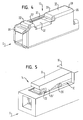
- FIG. 3 and 4 show in different perspective representations the protective housing 10, which in a connector housing 16 (see also Figure 5) of the connector part 14 can be used.
- a modified embodiment the protective housing is shown in FIG.
- the connector part 14 is with a second connector part of the electrical Connector pluggable together, for example, a connector to create between two electrical lines.
- the protective housing 10 comprises one in the longitudinal and plug-in direction S. extending, in particular vaulted or raised lid 18.
- This cover 18 has a window 20 cut out at one end a latching element 22 delimits and into the one with this latching element 22nd interacting locking arm 24 assigned to the connector housing 16 can be snapped into place (cf. in particular FIG. 5).
- the cover 18 for example curved side walls 26 and a flat top wall 28 full. H. in particular vaulted or raised his.
- the window 20 is now not just the upper flat wall 28 but also recessed the side walls 26 of the lid 18.
- Locking arm 24 of the connector housing 16 can be made correspondingly wider, which results in a more reliable locking.
- the wider one Locking arm 24 is also the manufacture of the relevant plastic injection mold simplified, reducing tool and service costs be reduced accordingly.
- the locking element 22 can now also be made correspondingly stronger, in particular a larger one with the locking arm 24 cooperating locking surface 22 '(cf. in particular Fig. 4) results.
- the latch arm 24 can be at least essentially as wide as the window Be 20. In the present case, it has a window 20 with the locking surface 22 'of the locking element 22 cooperating locking lug 24 '.
- the protective housing 10 can have a protective surface 32 (cf. in particular FIG. 4 again) in order to touch the electrical contact part 12 through the locking arm 24 or its locking lug 24 'to prevent.
- a protective surface 32 (cf. in particular FIG. 4 again) in order to touch the electrical contact part 12 through the locking arm 24 or its locking lug 24 'to prevent.
- the reinforced executed locking element 22 and the adjustable, d. H. in particular is optionally correspondingly lower positionable protective surface 32 ensures that pulling out of the electrical contact part 12 or the protective housing 10 from the connector housing 16 only under Application of a high force is possible.
- the protective housing 10 can in particular be made of spring steel and the connector housing 16 consist in particular of plastic.
- the electrical contact part 12 consists of a highly conductive material, which is in particular copper or a copper alloy can.
- connection section 36 is as Crimp area formed.
- the sleeve-shaped protective housing 10 is on the socket section 34 of the electrical contact part 12 can be plugged on.
- the protective housing can 10 at its end facing away from the connecting section 36
- Guide tabs 38 may be provided, which is a guide channel for one Form the relevant plug contact that an insertion opening 40 (see also Figure 1) of the electrical contact part 12 and the socket section 34th is upstream.
- the protective housing 10 can be formed as a one-piece stamped / bent part his.
- the electrical contact part 12 is also preferably in one piece Stamped / bent part executed.
- the cover 18 of the connector housing which is preferably made of plastic 16 can in principle also be other than vaulted or raised be executed.
- those with window 20 must be left out
- Side walls 26 must not necessarily be curved or curved.
- the top wall 28 of the cover 18 does not have to either inevitably be flat.
- Figure 6 shows a somewhat modified perspective view Embodiment of the protective housing 10. So in Figure 6 is an inner Reinforcement 42 for the locking element 22 can be seen, which from the lower Part of the protective housing is generally bent upwards.
- the cover 18 is provided with a connecting web 44, which Locking element 22 connects to the rest of the cover 18, whereby the risk of twisting or turning away the locking element 22 a minimum is reduced.
- the protective housing 10 can at least essentially again the same structure as the protective housing 10 described above (cf. in particular FIG. 4), with mutually corresponding ones Parts are assigned the same reference numerals.
Landscapes
- Details Of Connecting Devices For Male And Female Coupling (AREA)
- Connector Housings Or Holding Contact Members (AREA)
Abstract
Description
- Figur 1
- eine schematische perspektivische Darstellung eines elektrischen Kontaktteils sowie eines auf dieses aufgesteckten Schutzgehäuses eines Verbinderteils eines elektrischen Steckverbinders,
- Figur 2
- eine schematische perspektivische Darstellung des elektrischen Kontaktteils und des Schutzgehäuses gemäß Figur 1 aus einer anderen Blickrichtung,
- Figur 3
- eine schematische perspektivische Darstellung des Schutzgehäuses,
- Figur 4
- eine schematische perspektivische Darstellung des Schutzgehäuses aus einer anderen Blickrichtung,
- Figur 5
- eine schematische perspektivische Teildarstellung des Verbinderteils mit in ein Steckergehäuse eingesetztem Schutzgehäuse, in dessen Fenster der dem Steckergehäuse zugeordnete Rastarm eingerastet ist, und
- Figur 6
- eine schematische perspektivische Darstellung einer weiteren Ausführungsform des Schutzgehäuses.
- 10
- Schutzgehäuse
- 12
- elektrisches Kontaktteil
- 14
- Verbinderteil
- 16
- Steckergehäuse
- 18
- Deckel
- 20
- Fenster
- 22
- Rastelement
- 22'
- Rastfläche
- 24
- Rastarm
- 24'
- Rastnase
- 26
- Seitenwände des Deckels
- 28
- obere Wand des Deckels
- 32
- Schutzfläche
- 34
- Buchsenabschnitt
- 36
- Anschlussabschnitt
- 38
- Führungslasche
- 40
- Einführöffnung
- 42
- innere Verstärkung
- 44
- Verbindungssteg
- S
- Längs- oder Steckrichtung
Claims (17)
- Verbinderteil (14) eines elektrischen Steckverbinders, mit einem elektrischen Kontaktteil (12), das zumindest teilweise in einem Schutzgehäuse (10) untergebracht ist, das einen sich in Längs- und Steckrichtung (S) erstreckenden, insbesondere gewölbeartigen oder erhabenen Deckel (18) umfasst, in dem ein Fenster (20) ausgespart ist, das an einem Ende durch ein Rastelement (22) begrenzt und in das ein mit diesem Rastelement zusammenwirkender, einem Steckergehäuse (16) zugeordneter Rastarm (24) einrastbar ist, wobei mit dem Fenster (20) auch die Seitenwände (26) des insbesondere gewölbeartigen oder erhabenen Deckels (18) ausgespart sind.
- Verbinderteil nach Anspruch 1,
dadurch gekennzeichnet, dass im Bereich des Fensters (20) zumindest teilweise auch die an den Deckel (18) angrenzenden Seitenwände (26) des Schutzgehäuses (10) ausgespart sind. - Verbinderteil nach Anspruch 1 oder 2,
dadurch gekennzeichnet, dass das Rastelement (22) bügelartig ausgeführt ist. - Verbinderteil nach einem der vorhergehenden Ansprüche,
dadurch gekennzeichnet, dass das Rastelement (22) verstärkt ausgeführt ist. - Verbinderteil nach einem der vorhergehenden Ansprüche,
dadurch gekennzeichnet, dass der Rastarm (24) zumindest im Wesentlichen so breit wie das Fenster (20) ist. - Verbinderteil nach einem der vorhergehenden Ansprüche,
dadurch gekennzeichnet, dass der Rastarm (24) eine in das Fenster (20) eintretende Rastnase (24') besitzt. - Verbinderteil nach einem der vorhergehenden Ansprüche,
dadurch gekennzeichnet, dass das Schutzgehäuse (10) im Bereich des Fensters (20) eine Schutzfläche (32) aufweist, um eine Berührung des elektrischen Kontaktteils (12) durch den Rastarm (24) bzw. dessen Rastnase (24') zu verhindern. - Verbinderteil nach Anspruch 7,
dadurch gekennzeichnet, dass der Rastarm (24) bzw. dessen Rastnase (24') nach erfolgtem Einrasten in das Fenster (20) auf der Schutzfläche (32) aufliegt. - Verbinderteil nach einem der vorhergehenden Ansprüche,
dadurch gekennzeichnet, dass das Schutzgehäuse (10) aus Federstahl besteht. - Verbinderteil nach einem der vorhergehenden Ansprüche,
dadurch gekennzeichnet, dass das Steckergehäuse (16) aus Kunststoff besteht. - Verbinderteil nach einem der vorhergehenden Ansprüche,
dadurch gekennzeichnet, dass das elektrische Kontaktteil (12) aus Kupfer oder einer Kupferlegierung besteht. - Verbinderteil nach einem der vorhergehenden Ansprüche,
dadurch gekennzeichnet, dass das elektrische Kontaktteil (12) wenigstens einen im Schutzgehäuse (10) untergebrachten Buchsenabschnitt (34) umfasst. - Verbinderteil nach einem der vorhergehenden Ansprüche,
dadurch gekennzeichnet, dass das elektrische Kontaktteil (12) wenigstens einen außerhalb des Schutzgehäuses (10) liegenden Anschlußabschnitt umfasst. - Verbinderteil nach einem der vorhergehenden Ansprüche,
dadurch gekennzeichnet, dass das Schutzgehäuse (10) hülsenförmig ausgebildet und auf das elektrische Kontaktteil (12) bzw. dessen Buchsenabschnitt (34) aufsteckbar ist. - Verbinderteil nach einem der vorhergehenden Ansprüche,
dadurch gekennzeichnet, dass das Schutzgehäuse (10) an einem Ende mit Führungslaschen (38) versehen ist, die einen Führungskanal für einen Steckkontakt bilden, der einer Einführöffnung (40) des elektrischen Kontaktteils (12) bzw. des Buchsenabschnittes (34) vorgelagert ist. - Verbinderteil nach einem der vorhergehenden Ansprüche,
dadurch gekennzeichnet, dass das Schutzgehäuse (10) als einstückiges Stanz-/Biegeteil ausgebildet ist. - Verbinderteil nach einem der vorhergehenden Ansprüche,
dadurch gekennzeichnet, dass das elektrische Kontaktteil (12) als einstückiges Stanz-/Biegeteil ausgebildet ist.
Applications Claiming Priority (2)
| Application Number | Priority Date | Filing Date | Title |
|---|---|---|---|
| DE10150438 | 2001-10-12 | ||
| DE2001150438 DE10150438A1 (de) | 2001-10-12 | 2001-10-12 | Verbinderteil |
Publications (3)
| Publication Number | Publication Date |
|---|---|
| EP1303008A2 true EP1303008A2 (de) | 2003-04-16 |
| EP1303008A3 EP1303008A3 (de) | 2006-03-22 |
| EP1303008B1 EP1303008B1 (de) | 2007-08-08 |
Family
ID=7702310
Family Applications (1)
| Application Number | Title | Priority Date | Filing Date |
|---|---|---|---|
| EP20020022135 Expired - Lifetime EP1303008B1 (de) | 2001-10-12 | 2002-10-02 | Verbinderteil eines elektrischen Steckverbinders |
Country Status (2)
| Country | Link |
|---|---|
| EP (1) | EP1303008B1 (de) |
| DE (2) | DE10150438A1 (de) |
Cited By (4)
| Publication number | Priority date | Publication date | Assignee | Title |
|---|---|---|---|---|
| EP1689039A1 (de) * | 2005-02-02 | 2006-08-09 | Sumitomo Wiring Systems, Ltd. | Anschlusskontakt und Herstellungsverfahren |
| EP1780835A2 (de) | 2005-10-27 | 2007-05-02 | Yazaki Europe Ltd. | Elektrischer Kontakt |
| JP2010103049A (ja) * | 2008-10-27 | 2010-05-06 | Hirose Electric Co Ltd | 電気コネクタ |
| EP2355255A1 (de) * | 2010-02-02 | 2011-08-10 | Sumitomo Wiring Systems, Ltd. | Anschlussbuchse und damit ausgestatteter Steckverbinder |
Family Cites Families (5)
| Publication number | Priority date | Publication date | Assignee | Title |
|---|---|---|---|---|
| FR2621180B1 (fr) * | 1987-09-28 | 1990-01-12 | Francelco Sa | Borne de contact electrique de type cage |
| US5188545A (en) * | 1990-06-05 | 1993-02-23 | Amp Incorporated | Electrical socket terminal |
| FR2749442B1 (fr) * | 1996-06-03 | 1998-07-10 | Framatome Connectors Int | Borne de contact electrique femelle a structure reforcee |
| JP3509401B2 (ja) * | 1996-07-25 | 2004-03-22 | 住友電装株式会社 | 端子金具 |
| DE19828984A1 (de) * | 1998-06-29 | 1999-12-30 | Whitaker Corp | Zweiteiliger elektrischer Buchsenkontakt |
-
2001
- 2001-10-12 DE DE2001150438 patent/DE10150438A1/de not_active Withdrawn
-
2002
- 2002-10-02 DE DE50210630T patent/DE50210630D1/de not_active Expired - Lifetime
- 2002-10-02 EP EP20020022135 patent/EP1303008B1/de not_active Expired - Lifetime
Cited By (10)
| Publication number | Priority date | Publication date | Assignee | Title |
|---|---|---|---|---|
| EP1689039A1 (de) * | 2005-02-02 | 2006-08-09 | Sumitomo Wiring Systems, Ltd. | Anschlusskontakt und Herstellungsverfahren |
| US7229314B2 (en) | 2005-02-02 | 2007-06-12 | Sumitomo Wiring Systems, Ltd. | Terminal fitting |
| EP1780835A2 (de) | 2005-10-27 | 2007-05-02 | Yazaki Europe Ltd. | Elektrischer Kontakt |
| EP1780835A3 (de) * | 2005-10-27 | 2009-09-30 | Yazaki Europe Ltd. | Elektrischer Kontakt |
| JP2010103049A (ja) * | 2008-10-27 | 2010-05-06 | Hirose Electric Co Ltd | 電気コネクタ |
| US7942708B2 (en) | 2008-10-27 | 2011-05-17 | Hirose Electric Co., Ltd. | Electrical connector and terminal for electrical connector |
| EP2355255A1 (de) * | 2010-02-02 | 2011-08-10 | Sumitomo Wiring Systems, Ltd. | Anschlussbuchse und damit ausgestatteter Steckverbinder |
| CN102170067A (zh) * | 2010-02-02 | 2011-08-31 | 住友电装株式会社 | 端子接头和设置有该端子接头的连接器 |
| US8226436B2 (en) | 2010-02-02 | 2012-07-24 | Sumitomo Wiring Systems, Ltd. | Terminal fitting and connector provided therewith |
| CN102170067B (zh) * | 2010-02-02 | 2014-03-05 | 住友电装株式会社 | 端子接头和设置有该端子接头的连接器 |
Also Published As
| Publication number | Publication date |
|---|---|
| EP1303008A3 (de) | 2006-03-22 |
| DE10150438A1 (de) | 2003-04-17 |
| EP1303008B1 (de) | 2007-08-08 |
| DE50210630D1 (de) | 2007-09-20 |
Similar Documents
| Publication | Publication Date | Title |
|---|---|---|
| DE19812935C2 (de) | Elektrisches Steckverbinder-Anschlußstück | |
| DE19714459C2 (de) | Steckverbinder mit einer Gehäuseverriegelung | |
| DE2925938A1 (de) | Elektrischer flachsteckverbinder | |
| DE10256675A1 (de) | Erdungsanschluß und Verfahren zum Ausbilden desselben | |
| EP0111245B1 (de) | Verriegelbare elektrische Flachsteckbuchse und damit versehener elektrischer Verbinder | |
| DE69410834T2 (de) | Elektrischer Anschlussteil mit Mitteln zur Vermeidung von Beschädigungen der Einrastzungen und von Verwirrungen | |
| DE69611499T2 (de) | Steckverbindergehäuse mit einer Haube | |
| DE10012262A1 (de) | Buchsen- bzw. Mutter-Anschlußpaßstück | |
| DE2922448A1 (de) | Verbinder zum abschliessen eines flachen kabels | |
| DE10324521B4 (de) | Schmelzsicherung | |
| DE112012002503T5 (de) | Anschlusselement | |
| EP1303008B1 (de) | Verbinderteil eines elektrischen Steckverbinders | |
| EP1555728A1 (de) | Elektrischer Verbinder | |
| DE102004055297A1 (de) | Steckverbinderanordnung mit Sekundärverriegelung | |
| WO2002103853A1 (de) | Elektrische steckverbindung | |
| DE2746142A1 (de) | Elektrische anschluesse | |
| DE19736420B4 (de) | Elektrischer Verbinder, Verbindergehäuse und Verfahren zum Einbringen eines elektrischen Kontaktes in ein Verbindergehäuse | |
| EP0037995B1 (de) | Flachsteckhülse | |
| DE102007042983B4 (de) | Verbindergehäuse | |
| DE3302530A1 (de) | Blindabdeckstreifen fuer verteiler | |
| EP1056160B1 (de) | Verbindersystem | |
| DE102006027674B3 (de) | Elektrischer Buchsenkontakt | |
| DE3914872A1 (de) | Steckkontakttraeger aus kunststoff mit flachstecker | |
| DE8706058U1 (de) | Gehäuse einer elektrischen Schaltanlage | |
| DE19742934B4 (de) | Kontakt, Verbindergehäuse und elektrische Verbinderanordnung bestehend aus Kontakt und Verbindergehäuse |
Legal Events
| Date | Code | Title | Description |
|---|---|---|---|
| PUAI | Public reference made under article 153(3) epc to a published international application that has entered the european phase |
Free format text: ORIGINAL CODE: 0009012 |
|
| AK | Designated contracting states |
Designated state(s): AT BE BG CH CY CZ DE DK EE ES FI FR GB GR IE IT LI LU MC NL PT SE SK TR |
|
| AX | Request for extension of the european patent |
Extension state: AL LT LV MK RO SI |
|
| PUAL | Search report despatched |
Free format text: ORIGINAL CODE: 0009013 |
|
| AK | Designated contracting states |
Kind code of ref document: A3 Designated state(s): AT BE BG CH CY CZ DE DK EE ES FI FR GB GR IE IT LI LU MC NL PT SE SK TR |
|
| AX | Request for extension of the european patent |
Extension state: AL LT LV MK RO SI |
|
| 17P | Request for examination filed |
Effective date: 20060426 |
|
| AKX | Designation fees paid |
Designated state(s): DE FR IT |
|
| GRAP | Despatch of communication of intention to grant a patent |
Free format text: ORIGINAL CODE: EPIDOSNIGR1 |
|
| GRAS | Grant fee paid |
Free format text: ORIGINAL CODE: EPIDOSNIGR3 |
|
| GRAA | (expected) grant |
Free format text: ORIGINAL CODE: 0009210 |
|
| AK | Designated contracting states |
Kind code of ref document: B1 Designated state(s): DE FR IT |
|
| REF | Corresponds to: |
Ref document number: 50210630 Country of ref document: DE Date of ref document: 20070920 Kind code of ref document: P |
|
| ET | Fr: translation filed | ||
| PLBE | No opposition filed within time limit |
Free format text: ORIGINAL CODE: 0009261 |
|
| STAA | Information on the status of an ep patent application or granted ep patent |
Free format text: STATUS: NO OPPOSITION FILED WITHIN TIME LIMIT |
|
| 26N | No opposition filed |
Effective date: 20080509 |
|
| PGFP | Annual fee paid to national office [announced via postgrant information from national office to epo] |
Ref country code: DE Payment date: 20090923 Year of fee payment: 8 |
|
| PGFP | Annual fee paid to national office [announced via postgrant information from national office to epo] |
Ref country code: FR Payment date: 20091029 Year of fee payment: 8 Ref country code: IT Payment date: 20091014 Year of fee payment: 8 |
|
| PG25 | Lapsed in a contracting state [announced via postgrant information from national office to epo] |
Ref country code: FR Free format text: LAPSE BECAUSE OF NON-PAYMENT OF DUE FEES Effective date: 20101102 |
|
| REG | Reference to a national code |
Ref country code: FR Ref legal event code: ST Effective date: 20110630 |
|
| REG | Reference to a national code |
Ref country code: DE Ref legal event code: R119 Ref document number: 50210630 Country of ref document: DE Effective date: 20110502 |
|
| PG25 | Lapsed in a contracting state [announced via postgrant information from national office to epo] |
Ref country code: IT Free format text: LAPSE BECAUSE OF NON-PAYMENT OF DUE FEES Effective date: 20101002 |
|
| PG25 | Lapsed in a contracting state [announced via postgrant information from national office to epo] |
Ref country code: DE Free format text: LAPSE BECAUSE OF NON-PAYMENT OF DUE FEES Effective date: 20110502 |