EP1303003B1 - Protective covering for radio systems, components thereof, and methods of fabrication - Google Patents
Protective covering for radio systems, components thereof, and methods of fabrication Download PDFInfo
- Publication number
- EP1303003B1 EP1303003B1 EP01124547A EP01124547A EP1303003B1 EP 1303003 B1 EP1303003 B1 EP 1303003B1 EP 01124547 A EP01124547 A EP 01124547A EP 01124547 A EP01124547 A EP 01124547A EP 1303003 B1 EP1303003 B1 EP 1303003B1
- Authority
- EP
- European Patent Office
- Prior art keywords
- components
- support element
- protective covering
- insulation layer
- component
- Prior art date
- Legal status (The legal status is an assumption and is not a legal conclusion. Google has not performed a legal analysis and makes no representation as to the accuracy of the status listed.)
- Expired - Lifetime
Links
- 230000001681 protective effect Effects 0.000 title claims abstract description 108
- 238000000034 method Methods 0.000 title claims description 28
- 238000004519 manufacturing process Methods 0.000 title claims description 23
- 238000009413 insulation Methods 0.000 claims abstract description 38
- 229920002430 Fibre-reinforced plastic Polymers 0.000 claims abstract 3
- 239000000463 material Substances 0.000 claims description 59
- 239000006260 foam Substances 0.000 claims description 11
- 239000002131 composite material Substances 0.000 claims description 7
- 239000002245 particle Substances 0.000 claims description 6
- 239000000843 powder Substances 0.000 claims description 6
- 238000005520 cutting process Methods 0.000 claims description 5
- 230000009467 reduction Effects 0.000 claims description 4
- 239000011151 fibre-reinforced plastic Substances 0.000 claims 2
- 239000011521 glass Substances 0.000 claims 2
- 239000003365 glass fiber Substances 0.000 abstract description 6
- 238000005253 cladding Methods 0.000 abstract 1
- 239000006261 foam material Substances 0.000 abstract 1
- 239000010410 layer Substances 0.000 description 97
- 238000010521 absorption reaction Methods 0.000 description 16
- 230000005670 electromagnetic radiation Effects 0.000 description 13
- 239000011152 fibreglass Substances 0.000 description 12
- 229920002635 polyurethane Polymers 0.000 description 7
- 239000004814 polyurethane Substances 0.000 description 7
- 229920005830 Polyurethane Foam Polymers 0.000 description 5
- 230000001070 adhesive effect Effects 0.000 description 5
- 230000008901 benefit Effects 0.000 description 5
- 229920003023 plastic Polymers 0.000 description 5
- 239000004033 plastic Substances 0.000 description 5
- 239000011496 polyurethane foam Substances 0.000 description 5
- 239000000088 plastic resin Substances 0.000 description 4
- 239000011253 protective coating Substances 0.000 description 4
- 239000011810 insulating material Substances 0.000 description 3
- 238000003801 milling Methods 0.000 description 3
- 238000012545 processing Methods 0.000 description 3
- 230000009471 action Effects 0.000 description 2
- 239000000853 adhesive Substances 0.000 description 2
- 238000004026 adhesive bonding Methods 0.000 description 2
- 238000004378 air conditioning Methods 0.000 description 2
- 239000011324 bead Substances 0.000 description 2
- 230000015572 biosynthetic process Effects 0.000 description 2
- 230000008859 change Effects 0.000 description 2
- 230000001427 coherent effect Effects 0.000 description 2
- 238000001816 cooling Methods 0.000 description 2
- 230000001419 dependent effect Effects 0.000 description 2
- 239000004744 fabric Substances 0.000 description 2
- 238000009415 formwork Methods 0.000 description 2
- 238000010438 heat treatment Methods 0.000 description 2
- 239000012774 insulation material Substances 0.000 description 2
- 238000005304 joining Methods 0.000 description 2
- 229920000728 polyester Polymers 0.000 description 2
- 230000003716 rejuvenation Effects 0.000 description 2
- 239000011800 void material Substances 0.000 description 2
- 229920000049 Carbon (fiber) Polymers 0.000 description 1
- 229920006328 Styrofoam Polymers 0.000 description 1
- 241000826860 Trapezium Species 0.000 description 1
- 239000012790 adhesive layer Substances 0.000 description 1
- 238000005452 bending Methods 0.000 description 1
- 230000005540 biological transmission Effects 0.000 description 1
- 239000004917 carbon fiber Substances 0.000 description 1
- 239000003086 colorant Substances 0.000 description 1
- 238000001035 drying Methods 0.000 description 1
- 238000005516 engineering process Methods 0.000 description 1
- 230000007613 environmental effect Effects 0.000 description 1
- 238000011049 filling Methods 0.000 description 1
- 239000007789 gas Substances 0.000 description 1
- 239000003292 glue Substances 0.000 description 1
- 238000009434 installation Methods 0.000 description 1
- 238000002955 isolation Methods 0.000 description 1
- 239000007788 liquid Substances 0.000 description 1
- 238000003754 machining Methods 0.000 description 1
- 239000002184 metal Substances 0.000 description 1
- 239000003973 paint Substances 0.000 description 1
- 230000035699 permeability Effects 0.000 description 1
- 238000012805 post-processing Methods 0.000 description 1
- 238000002360 preparation method Methods 0.000 description 1
- 230000005855 radiation Effects 0.000 description 1
- 229910052704 radon Inorganic materials 0.000 description 1
- SYUHGPGVQRZVTB-UHFFFAOYSA-N radon atom Chemical compound [Rn] SYUHGPGVQRZVTB-UHFFFAOYSA-N 0.000 description 1
- 230000008439 repair process Effects 0.000 description 1
- 238000007789 sealing Methods 0.000 description 1
- 239000003566 sealing material Substances 0.000 description 1
- 239000008261 styrofoam Substances 0.000 description 1
- 239000000057 synthetic resin Substances 0.000 description 1
- 229920003002 synthetic resin Polymers 0.000 description 1
- 229920001187 thermosetting polymer Polymers 0.000 description 1
Images


Classifications
-
- E—FIXED CONSTRUCTIONS
- E04—BUILDING
- E04C—STRUCTURAL ELEMENTS; BUILDING MATERIALS
- E04C2/00—Building elements of relatively thin form for the construction of parts of buildings, e.g. sheet materials, slabs, or panels
- E04C2/02—Building elements of relatively thin form for the construction of parts of buildings, e.g. sheet materials, slabs, or panels characterised by specified materials
- E04C2/26—Building elements of relatively thin form for the construction of parts of buildings, e.g. sheet materials, slabs, or panels characterised by specified materials composed of materials covered by two or more of groups E04C2/04, E04C2/08, E04C2/10 or of materials covered by one of these groups with a material not specified in one of the groups
- E04C2/284—Building elements of relatively thin form for the construction of parts of buildings, e.g. sheet materials, slabs, or panels characterised by specified materials composed of materials covered by two or more of groups E04C2/04, E04C2/08, E04C2/10 or of materials covered by one of these groups with a material not specified in one of the groups at least one of the materials being insulating
- E04C2/296—Building elements of relatively thin form for the construction of parts of buildings, e.g. sheet materials, slabs, or panels characterised by specified materials composed of materials covered by two or more of groups E04C2/04, E04C2/08, E04C2/10 or of materials covered by one of these groups with a material not specified in one of the groups at least one of the materials being insulating composed of insulating material and non-metallic or unspecified sheet-material
-
- E—FIXED CONSTRUCTIONS
- E04—BUILDING
- E04C—STRUCTURAL ELEMENTS; BUILDING MATERIALS
- E04C2/00—Building elements of relatively thin form for the construction of parts of buildings, e.g. sheet materials, slabs, or panels
- E04C2/02—Building elements of relatively thin form for the construction of parts of buildings, e.g. sheet materials, slabs, or panels characterised by specified materials
- E04C2/10—Building elements of relatively thin form for the construction of parts of buildings, e.g. sheet materials, slabs, or panels characterised by specified materials of wood, fibres, chips, vegetable stems, or the like; of plastics; of foamed products
- E04C2/24—Building elements of relatively thin form for the construction of parts of buildings, e.g. sheet materials, slabs, or panels characterised by specified materials of wood, fibres, chips, vegetable stems, or the like; of plastics; of foamed products laminated and composed of materials covered by two or more of groups E04C2/12, E04C2/16, E04C2/20
- E04C2/246—Building elements of relatively thin form for the construction of parts of buildings, e.g. sheet materials, slabs, or panels characterised by specified materials of wood, fibres, chips, vegetable stems, or the like; of plastics; of foamed products laminated and composed of materials covered by two or more of groups E04C2/12, E04C2/16, E04C2/20 combinations of materials fully covered by E04C2/16 and E04C2/20
-
- E—FIXED CONSTRUCTIONS
- E04—BUILDING
- E04C—STRUCTURAL ELEMENTS; BUILDING MATERIALS
- E04C2/00—Building elements of relatively thin form for the construction of parts of buildings, e.g. sheet materials, slabs, or panels
- E04C2/30—Building elements of relatively thin form for the construction of parts of buildings, e.g. sheet materials, slabs, or panels characterised by the shape or structure
- E04C2/32—Building elements of relatively thin form for the construction of parts of buildings, e.g. sheet materials, slabs, or panels characterised by the shape or structure formed of corrugated or otherwise indented sheet-like material; composed of such layers with or without layers of flat sheet-like material
- E04C2/328—Building elements of relatively thin form for the construction of parts of buildings, e.g. sheet materials, slabs, or panels characterised by the shape or structure formed of corrugated or otherwise indented sheet-like material; composed of such layers with or without layers of flat sheet-like material slightly bowed or folded panels not otherwise provided for
-
- H—ELECTRICITY
- H01—ELECTRIC ELEMENTS
- H01Q—ANTENNAS, i.e. RADIO AERIALS
- H01Q1/00—Details of, or arrangements associated with, antennas
- H01Q1/42—Housings not intimately mechanically associated with radiating elements, e.g. radome
Definitions
- the invention relates to protective coatings for radio systems, methods for producing such protective coverings, components for such protective coatings, wherein the components comprise an insulating layer, and to methods for producing such components.
- Protective covers for radio systems are used to protect the radio or transmitter systems on transmission towers or radar systems from environmental and weather influences.
- radar systems such protective coverings often have the shape of a dome and are referred to as radomes.
- Such protective coverings should generally have a low absorption behavior for the electromagnetic radiation of the respective radio or radar system. As a result, the attenuation of the signal intensity of the electromagnetic radiation through the protective covering is only slight.
- FIG. 11 It is known to produce protective coverings of this type from a rigid polyurethane (PUR) foam.
- PUR polyurethane
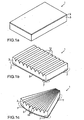
- FIG. 11 Such a known protective cover is in FIG. 11 shown.
- the radio system is inside the in FIG. 11 arranged cylinder arranged.
- the individual components 21,22 of the protective cover 20 are produced as curved components 21,22 in molds and arranged side by side during assembly on site via a Jardinnfalz.
- the resulting joints 24 are foamed with the aid of formwork 23 with hardening foam so as to connect the components 21,22 together. Since the components 21, 22 are self-supporting, they must have a certain stability so that the material of which they are made typically has a density of 200 kg / m 3 to 250 kg / m 3 .
- a disadvantage of such protective coverings is that they tend to crack formation under strong temperature fluctuations and easily accumulates on the surface of the protective covering ice and snow. The weight of the ice and snow can pose a certain risk of collapse for the fairing.
- the object of the present invention is therefore to provide a component and a protective covering as well as the respective production methods with which a simple assembly of the components to form a protective lining is possible.
- the object is achieved by a protective covering according to claim 1 and a method for producing a protective lining according to claim 17.
- the component according to the invention has a support element which is provided on one side of the hard foam layer.
- the support element essentially assumes the supporting or self-supporting task of the component, so that the insulation layer can be optimized with respect to other criteria than the supporting function. For example, it is possible to optimize the insulation layer with respect to the insulating property. This makes it possible to improve the insulation properties so that can be largely dispensed within the protective cover on air conditioning, heating or cooling. Furthermore, it is possible to provide the insulating layer with a low density, so that overall the weight of the components kept as low as possible who can. The low weight is a great advantage for the assembly because it eliminates the need for cranes.
- the insulation layer may be made of a rigid foam, for example.
- An example of this is polyurethane (PUR) foam.
- PUR polyurethane
- any other insulation material is conceivable.
- PUR polyurethane
- An example of such a material is about Styrofoam.
- the support element is made of a composite material and in this case preferably made of a glass fiber reinforced plastic (GRP).
- Composite materials are materials that are made up of two different ones Composing materials, wherein a material is usually fibrous. For example, glass or carbon fibers are known.
- the second fabric is typically a cured plastic, such as polyester-derived polyester or the like.
- Composite materials can be produced in any shape and are resistant to bending and torsion, as well as being break-resistant, even with thin material thicknesses.
- the support element is in direct contact with the insulating layer. While between the support member and the insulating layer various other materials may be provided, such. As adhesive layers or layers that affect the permeability of certain liquids or gases, it is advantageous if the support element is provided in direct contact with the insulating layer.
- the as yet uncured foam has good adhesiveness, so that the insulating layer can be made in a very stable contact with the supporting element.
- a later detachment of the insulating layer from the support element is very unlikely.
- the support element during its manufacture or processing at least temporarily has strong adhesive properties, so that the support element has a good relationship with the insulation layer.
- a particularly advantageous embodiment of the component according to the invention results from the fact that the support element in the form of a layer is preferably provided on the entire surface of at least one side of the insulating layer.
- the protective cover absorbs the electromagnetic waves as homogeneously as possible in all spatial directions, if at all, only weakly. Characterized in that the support element over the entire surface of the insulating layer is provided, thus results in a homogeneous absorption of the in / out of the protective cover / exiting electromagnetic radiation. Furthermore, it is advantageous for the stability of the component when the support element extends over the entire surface of one side of the insulation layer.
- a particularly advantageous embodiment of the component according to the invention results from the fact that the component and / or the support element and / or the insulation layer tapers towards the ends of the component.
- the taper By the taper, it is possible to connect the components together so that no bead or such forms after connecting two adjacent components at the junction.
- the space obtained by the taper can thus be used to connect the components.
- This makes it possible to have a smooth, i. To obtain a bead-free surface, on the ice and snow on the surface can slip well, so that the protective cover is not loaded.
- the taper of the component can be realized both by a taper of the support element, as well as by a taper of the insulating layer or a combination of the two.
- the component is curved flat or in one direction.
- the planar embodiment of the component can be produced inexpensively, since components of different sizes can be produced on a single predetermined level.
- a component that is curved is particularly well suited if the entire protective covering is curved as a whole.
- the component according to the invention advantageously has blunt ends.
- the blunt ends can be easily glued together by insulation material, such as polyurethane foam.
- the insulating layer material preferably has a density in the range of 40 kg / m 3 to 160 kg / m 3 , in particular a density in the range of 80 kg / m 3 , both for the insulating properties, as well as for the weight of the component taking into account the stability requirements optimal.
- a further particularly advantageous embodiment of the invention consists in that the component has slots on one side, wherein the side is preferably the side opposite the support element.
- the slots may extend into the insulating layer and also form slots in the support member.
- the slitting of the component on one side results in the component being able to be curved by the action of an external force, so that even with a component that was flat prior to the slitting, it can be used to produce curved protective coatings.
- the slots advantageously have a depth of max. half the thickness of the component, however, the depth may also be much larger or substantially smaller.
- At least two slots or at least two groups of essentially parallel slots are provided which have different directions.
- a fan-shaped arrangement of the slots it is possible to bend the component to a conical shell part.
- the curvature at one end of the component is thus greater than the curvature at another end of the component.
- a particularly advantageous embodiment of the invention consists in that the support element comprises color particles in powder form.
- a later coat or other repair paints, which lead to further costs, can be avoided.
- An inventive method for producing a component according to the invention comprises the production of an insulating layer and a supporting element connected thereto.
- a component according to the invention there are several possibilities to produce the various components of the component and to connect them together. It is for example possible according to the invention to manufacture the support element and the insulating layer separately from each other and then to connect to each other, for example, to bond together.
- Particularly advantageous in this case is the production of the support element or the insulating layer in a component form.
- This smooth surface is of great advantage for the protective covering which is produced with such a component, since ice and snow can thereby slide down on the surface of the component and thus on the surface of the protective covering and do not remain exposed on the surface.
- a component form is advantageous in order to predetermine the outer shape of the component during manufacture.
- a subsequent aftertreatment for example by cutting or sawing, in order to achieve a desired outer geometry of the component is therefore not necessary.
- such a component form is advantageous in which the taper of the component results towards its ends. If, for example, a component tapering towards its ends is produced, then a corresponding component shape would have a deviation from the flat structure toward the ends of the component form, for example in the form of a bead or a bevel, so that the component is tapered.
- the support element can be made equal with a corresponding taper towards the ends.
- a post-processing is possible, so that a rejuvenation results from a mechanical processing.
- a component form is advantageous in which slots are already formed by the component shape in the finished manufactured component. It is also possible in the method according to the invention to produce the slots by mechanical means by sawing, milling or cutting or the like.
- connection means in which the individual components are connected to one another by means of a connection means, the connection preferably being gluing includes.
- the connecting means used for joining is advantageously the same material from which the insulating layer of the component was made.
- the components it is advantageous to connect the components to one another on the inside and / or outside of the protective covering with connecting material.
- the material is used, which is also the material of the support member of the components.
- This is of particular advantage for the homogeneity of the absorption of the electromagnetic radiation by the protective covering.
- it is possible to create a coherent surface on the outside of the protective covering, which consists entirely of the material of the support element or the support elements. It can be as a whole produce a very smooth surface on the ice and snow can easily slide down, so that the risk of collapse of such a protective cover is almost zero by the weight of ice and snow.
- fiberglass-reinforced plastic is used as the material for the support element, it is possible, for example, to apply one or more layers of glass fibers in the tapers of the components at their ends and then to apply a corresponding plastic resin in the region of the tapers of the ends of the components.
- a taper of the components has been realized by a taper of the support element, it is thus possible to ensure a uniform layer thickness of the material of the support element over the junction of two components.
- the layer thickness may in this case be equal to the layer thickness of the support element of the components.
- the protective covering according to the invention in which the entire protective covering consists exclusively of the material of the supporting element and the insulating layer material.
- the absorption behavior with respect to the electromagnetic radiation of the protective covering is very homogeneous or very low overall.
- Metal connecting parts or connecting parts protruding from the protective lining would greatly disturb this homogeneity.
- Embodiments of the component according to the invention for a protective covering of radio systems, the method according to the invention for producing a component for a protective covering of radio systems, a protective covering of radio systems according to the invention, and the method for producing a protective covering for radio systems will be explained below with reference to the attached figures.
- a component 1 according to the invention which comprises an insulating layer 3 and a supporting element 2.
- the layer thickness of the support element 2 will generally be in the range of a few mm and that of the insulating layer 3 in the range of a few cm.
- the outer shape of the component 1 in Fig. 1a is rectangular in plan view.
- the dimensions along the longitudinal sides of the component 1 are typically between a few decimeters and a few meters.
- Fig. 1b an inventive component 1 is shown, in which at the ends tapers 7 of the support element 2 are provided and arranged on its upper side parallel, similar slots 14 in the region of the insulating layer 3 has. Because of the slots 14, the component 1 can be curved. As a result of the taper 7, the components 1, as described further below, can be connected to one another in a particularly advantageous manner to form a protective lining. Even if the rejuvenation 7 in Fig. 1b can be seen only on the right and left sides, it can also be provided according to the invention at the front and / or rear.
- a component 1 according to the invention which has the outer shape of a curvilinear trapezium in plan view.
- Such shapes are advantageous, for example, in the formation of domes for a radome.
- Such forms arise, for example, between latitude and longitude circles on the globe, or on maps of the globe.
- Fig. 1a to Fig. 1c shown rectangular or curvilinear trapezoidal shapes also round, triangular, hexagonal or interlocking forms of components 1 may be possible.
- the outer shape is arbitrary.
- the support element 2 in Fig. 1a to Fig. 1c is made of single or multi-layer glass fiber reinforced plastic and the insulation layer 3 made of PUR foam.
- the glass fiber reinforced plastic can be colored with color particles.
- the support element 2 is in the in Fig. 1a to Fig. 1c illustrated embodiment provided only on one side of the insulating layer 3. Furthermore, the support element 2 is provided in the form of a layer which extends over the entire side of the insulation layer 3. However, the support member 2 may also have the shape of one or more ribs or frames provided on the insulating layer 3.
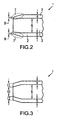
- Fig. 2 a sectional drawing of the end of a component 1 according to the invention is shown.
- the insulating layer 3 is provided with the thickness 6.
- a support member 2 In the embodiment in FIG Fig. 2 is provided on both sides of the insulating layer 3, a support member 2.
- the thickness 4 and the thickness 5 of the support elements 2 on the top and bottom of the insulating layer 3 are generally different, but may be the same. As a rule, the thickness 4 and 5 is significantly smaller than the thickness 6 of the insulating layer 3.
- a taper 7 of the component 1 is provided towards its end. This is the case in the embodiment which is in Fig. 2 is achieved, characterized in that the thickness 4 of the upper support member 2 is reduced to the left to a thickness 8.
- the thickness 8 can also be zero.
- the layer thickness 6 of the insulating layer 3 between the tapers 7 remains unchanged.
- a further embodiment of a component 1 according to the invention is shown in which are also provided on the top and bottom tapers of the component 1 at the left end of the component 1.
- the layer thickness 6 of the insulating layer 3 is reduced to the left end of the component 1 out to a layer thickness 10, whereby the taper of the component 1 results towards its end.
- the layer thicknesses 4 and 5 of the support elements 2 can change to the left end in each case to the layer thicknesses 11 and 12.
- a stronger or less pronounced taper of the component 1 towards the left end can be achieved, in comparison to the sole tapering of the component 1 by the tapering of the layer thickness 6 to the layer thickness 10 of the insulation layer 3.
- the reduction of the layer thickness must be 4.5 , 6 on each of the layer thickness 11,12,10 non-linear, but may also be stepped or curvilinear.
- support elements 2 on both sides of the insulating layer 3 in the Fig. 2 and Fig. 3 is optional. According to the invention, it is also possible to provide the support element 2 only on one side.
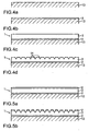
- FIG. 4 various steps of an embodiment according to the invention of the method for producing a component 1 for a radio system are shown.
- a plane 13 is shown on which the component 1 is produced.
- the plane 13 here is the component form 13.
- At the right and left end of the plane 13 can also be provided upwardly extending walls that can limit the component 1 side.
- a layer of a material for the support member 2 is applied.
- a thin layer of a plastic powder provided with color powder is applied to the plane 13.
- glass fibers in the form of mats or mesh are placed and impregnated with the plastic resin.
- the application of synthetic resin and fiberglass material can be done alternately, which can be started both with fiberglass and plastic material.
- One or more layers of the plastic material used to make the support member 2 may be provided with colorant particles.
- an insulating layer 3 is connected to the support member 2.
- This insulating layer 3 can be produced, for example, by applying a polyurethane foam material to the support element 2 and curing it there. Before curing, the polyurethane foam is usually very sticky, so that there is a good connection with the support element 2 after curing. A rough top of the support member 2 is for a good connection with the insulating layer 3 is advantageous because so interlock both materials.
- the insulation layer 3 separately and then to apply it to the support element 2 with a connection step.
- This may include, for example, a gluing.
- Fig. 4d an optional step in the manufacture of a component 1 according to the invention is shown.
- one or more slots 14 are provided on the upper side of the component 1. These slots 14 can be made by cutting, milling, sawing, etc., ie generally by machining, in particular mechanical.
- the component 1 does not necessarily have to lie on the mold 13.
- the depth of the slots 14 may extend to close to the plane 13, but is advantageously not deeper than half the thickness of the component 1.
- a manufacturing step is shown, which is based on the in Fig. 4c can follow the step shown.
- a further support member 2 is applied to the top of the insulating layer 3.
- This further support element 2 can be made similar to the insulating layer 3, as the support element 2 in Fig. 4 b at level 13, as described above.
- the support element 2 shown in FIG. 2 above on the insulating layer 3 Fig. 5a manufacture separately and then connect with a connection step with the insulating layer 3.
- the bonding can be, for example, bonding with polyurethane foam or other suitable adhesives. It is also possible to apply the separately prepared, further top support element 2 prior to curing of the material of the insulating layer 3 and thus also exploit the adhesive properties of the insulating material 3 before curing.
- the illustrated process step can be adapted to the in Fig. 4d and to the in Fig. 5a Connect the step shown.
- Starting from the state in Fig. 4d is applied to the top of the insulating layer 3 in the areas in which no slot 14 is provided, a further layer of the material of the support member 2 so as to form a plurality of support elements 2 between the slots 14.
- Fig. 5a is again made by mechanical processing, ie milling, cutting, sawing, etc., one or more slots 14 on the top of the component 1. Again, the depth of the slots 14 is advantageously max. half the thickness of the component 1.
- Fig. 4d and Fig. 5b can be adapted to any requirements.
- the width is in Fig. 4d and 5b for the sake of clarity shown exaggerated.
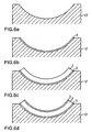
- FIG. 6 Another possible embodiment of the method according to the invention is based on Fig. 6 explained.
- Fig. 6a a mold 13 is shown in which the top is curved is.
- the curvature can be from semicircular to almost flat.
- Fig. 4b, 4c and Fig. 5a be in the process steps that in Fig. 6b, 6c and 6d are shown, an inventive component 1 produced.
- the step in Fig. 6d is shown, ie the application of a further support member 2, is optional.
- the ends of the component 1 can be configured, for example, by borders of the component form 13 'at their upper ends so that they terminate perpendicular to the course of the surfaces of the component 1.
- a slit 14, which allows the components 1 to bend, is not absolutely necessary in the case of the curved components 1, but may also be provided according to the invention.
- Fig. 4c, 4d, 5a, 5b . 6c and 6d shown components 1 can be edited at a further process step at their ends. In this case, for example, by tapering the ends tapers 7 are attached. It is also possible to change the angle which the end surface encloses with the side surfaces of the component 1. In the embodiments as they are in Fig. 4c, 4d, 5a, 5b . 6c and 6d are shown, the angle is 90 °, but other angles are possible.
- Fig. 7a and 7b is a perspective and a sectional drawing of a protective panel 17 according to the invention shown.
- the protective cover 17 in Fig. 7a is cylindrical and consists of two rows of 6 components 1 together.
- the radio system to be protected is arranged inside the cylinder, but not shown here.
- the upper and lower ends are closed by appropriate documents or coverings.
- the pad or the cover must meet any special requirements regarding the absorption of electromagnetic radiation and therefore may be arbitrary.
- the components 1 are connected to one another along straight-line connecting lines. However, the connecting lines do not necessarily have to be straight, but can also be curvilinear.
- For producing a protective cover 17, as in Fig. 7a can be shown, for example, in Fig. 1b . 4d . 5b .
- FIG. 7b the possibility is shown in which a slotted component 1, for example as in Fig. 1b . 4d or 5b shown is used.
- the slotted components 1 are curved for assembly, the curvature being made possible by the slots 14 on one side of the components 1.
- FIG. 8a and 8b Another embodiment of a protective cover 18 according to the invention is in the Fig. 8a and 8b shown.
- the angle between the end surface and the lateral surface of the components 1 is not 90 °, but the end surface is slightly bevelled in comparison.
- the protective cover 18 is composed of three rows of 6 components 1 each.
- shown protective cover 17 and 18 is not limited to six. There are also significantly more components 1 in each row possible, for example, several 10 to several 100. However, in principle, a single component 1 for the protective cover 17, which forms a curved cylinder, according to the invention possible.
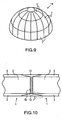
- a further embodiment of a protective covering 19 according to the invention is shown.
- the protective cover 19 here has the overall shape of a dome 19, as used for example in a radon.
- the radio system such as a radar can be arranged under the dome.
- the dome 19 will be placed on a suitable surface.
- the components 1 have no rectangular shape, but are substantially trapezoidal. There are provided here 3 rows of components 1, wherein the lower two rows have the same number of components 1. However, the rows can also have different number of components 1. For example, the third and top row has a smaller number of components 1 than the two bottom rows.
- the top row of components 1 can taper at its upper end, so that Seen from the outside, they have the overall shape of a curvilinear triangle, but the upper end of the dome 19 can also be formed by a type of closing element, as in FIG FIG. 9 shown.
- a protective cover 19 in the form of a dome, as in Fig. 9 can also be created by assembling planar components 1 without slots 14. The result is a polygon surface similar to the one in FIG. 8 , but closed up. A large number of components 1 is advantageous in this case, since then the angles at which the components 1 abut one another become approximately 180 °.
- the support member 2 of the components 1 on the outside of the protective cover.
- the outside can be very smooth, resulting in a very smooth outer surface of the protective covering. This allows ice and snow to slip well on the fairing and the weight that the protective fairing 17, 18, 19 must hold is not very large.
- FIG Fig. 10 The manner in which it is possible according to the invention to join the various components 1 to the protective coverings 17, 18 or 19 is shown in FIG Fig. 10 shown.
- the components 1 comprise the insulating layer 3 and, in the in Fig. 10 shown embodiment, respectively, an upper and an optional lower support element 2.
- the two workpieces 1 are each provided with a taper 7 at the ends facing each other.
- the taper 7 is realized here by the taper 7 of the support element 2, but can also, as shown above, additionally or exclusively by tapering 7 of the insulation layer 3 can be achieved.
- the components 1 are shown slightly spaced. However, the components 1 can also completely meet, so that the connecting means 16 is present only in the resulting cavities between the two components 1.
- the connecting means 16 may, for. B. be the same material from which the insulation layer 3 was made. Particularly suitable is the PUR foam, which is available for on-site assembly in pressure cans.
- the extension of the connecting means 16 upwards or downwards is preferably equal to the layer thickness of the insulating layer 3, but may also include the thickness of the insulating layer 3 plus the thickness of the supporting element (s) 2 at the ends. Other dimensions are possible according to the invention.
- the connecting means 16 In the event that the material of the connecting means 16 is equal to the insulating layer 3, and also in the case that the extension of the connecting means 16 along the thickness of the components 1 is equal to the thickness of the insulating layer 3, thus results in a continuous area, which is made of one and the same material with one and the same layer thickness and thus a completely homogeneous absorption with respect to the electromagnetic radiation of the radio system.
- other connecting means 16 than the material of the insulating layer 3 and other dimensions along the thickness of the component 1 of the connecting means 16 can also be selected.
- the connecting means 16 may also be omitted according to the invention, since the components can also be connected to one another at their outer / inner side.
- this empty space 15 can now be filled with connecting material in order to establish the connection between the components 1.
- the empty space 15 is preferably filled with the material from which the support element 2 of the components 1 was produced. This has the advantage that the absorption of the electromagnetic radiation in the region of the connection is the same as in the region of the components 1.
- the thickness of the material in the region 15 may be greater / smaller than the layer thickness of the support element 2 of the components 1.
- a protective covering 17,18,19 for a radio system as in Fig. 7a is shown, already curved components 1, as in Fig. 6c and 6d shown used. It is also possible slotted components 1, as in Fig. 1b, 1c . 4d and 5b shown to use.
- the slotted components 1 are curved by the action of an external force, in one direction, so that the slits 14 lie on the curvature inside and thus at least partially close.
- the components 1 are assembled with a connection technique which will be described later. It is advantageous here to assemble the protective covering 17, 18, 19 from a plurality of individual components 1. Thereby, the weight of the components 1 can be kept in a range which makes it possible to mount the components 1 solely with human power, ie in particular without cranes. Thus, protective coverings with several meters or several tens of meters can be built.
- a protective cover 18 for a radio system as in Fig. 8a and 8b can be shown, planar components 1, as shown in Fig. 4c and 5a are shown used.
- the ends of the components 1 will be provided obliquely angled.
- FIG. 9 For protective panels 19 in the form of a dome, as in FIG. 9 can be shown, advantageously components 1 of the type Fig. 1c be used, since a curvature in different directions at different points of the component 1 is possible.
- the other components 1 from the FIGS. 1a, 1b . 4c, 4d . 5a, 5b . 6c, 6d can be used.
- the components 1 of a protective cover 17, 18, 19 are assembled with the connection technique described below to form a protective cover 17, 18, 19.
- the components 1 are supported and held by appropriate devices or by hand at their predetermined place.
- a connecting means 16, e.g. PUR foam is injected into the space between the blunt ends of the components 1. It glues there with the ends of the components 1 and connects them firmly after curing.
- connection means 16 it is also possible according to the invention to first provide a surface, which abuts a component 1 to be assembled, with the connection means 16, then to insert the component 1 to be mounted and to let the connection means 16 dry or harden.
- the components 1 can thereby abut each other directly or even slightly spaced apart from each other.
- the connecting means 16 is optional, since the components 1 are also connected to one another by the step described below.
- the connecting material is applied, from which the support member 2 of the components 1 has been prepared. If tapers 7 are provided at the ends of the components 1, the application takes place in the space 15 created by the taper 7. If the support element 2 of the components 1 is made of fiberglass, the connecting material will advantageously also be fiberglass.
- the GRP is applied by applying thermosetting plastic resin and glass fibers in the form of mats or fabric. The plastic resin is advantageously colored with color particles, so that after joining the components 1, a uniform outer color or color scheme of the protective panel 17,18,19 results.
- the GRP material adheres to the components 1 outside and / or inside, hardens and connects the components 1 with each other so. On the outside, a smooth coherent layer of the material from which the support elements 2 of the components 1 are made is ideally obtained.
- connection of the components 1 can also take place on the inside of the protective covering 17,18,19. This is particularly useful if support elements 2 of the components 1 are also provided on the inside.
- connection with the connecting material in the voids 15 need not necessarily occur. However, it would then be advantageous to seal the joints between the support elements 2 of the various components 1, at least on the outside of the protective cover 17, 18, 19.
- the sealing can be done with suitable sealing materials or with a material from which the support elements 2 of the components 1, eg GRP or even just e.g. Polyestherharz are made.
- the components 1 according to the invention and the connection technology according to the invention it is possible to provide a protective covering 17, 18, 19 according to the invention whose absorption in the region of the connection points is virtually identical to the absorption of the components 1 in a region outside the connection points.
- the finished protective cover 17,18,19 may have a smooth surface on the ice and snow slip well. Due to the good insulation properties are special heating, cooling, or air conditioning systems for the interior of the protective cover 17,18,19 in which the radio system is located, not or only with very low power necessary.
Landscapes
- Engineering & Computer Science (AREA)
- Architecture (AREA)
- Civil Engineering (AREA)
- Structural Engineering (AREA)
- Life Sciences & Earth Sciences (AREA)
- Wood Science & Technology (AREA)
- Laminated Bodies (AREA)
- Details Of Garments (AREA)
- Professional, Industrial, Or Sporting Protective Garments (AREA)
- Details Of Aerials (AREA)
- Shielding Devices Or Components To Electric Or Magnetic Fields (AREA)
- Burglar Alarm Systems (AREA)
- Telephone Set Structure (AREA)
Abstract
Description
Die Erfindung betrifft Schutzverkleidungen für funktechnische Anlagen, Verfahren zur Herstellung solcher Schutzverkleidungen, Bauteile für solche Schutzverkleidungen, wobei die Bauteile eine Isolationsschicht umfassen, sowie Verfahren zur Herstellung für derartige Bauteile.The invention relates to protective coatings for radio systems, methods for producing such protective coverings, components for such protective coatings, wherein the components comprise an insulating layer, and to methods for producing such components.
Schutzverkleidungen für funktechnische Anlagen dienen dazu, die Funk- bzw. Sendeanlagen auf Sendemasten oder Radarsysteme vor Umwelt- und Wettereinflüssen zu schützen. Bei Radarsystemen haben solche Schutzverkleidungen oft die Form einer Kuppel und werden als Radom bezeichnet.Protective covers for radio systems are used to protect the radio or transmitter systems on transmission towers or radar systems from environmental and weather influences. In radar systems, such protective coverings often have the shape of a dome and are referred to as radomes.
Derartige Schutzverkleidungen sollten in der Regel ein niedriges Absorptionsverhalten für die elektromagnetische Strahlung der jeweiligen Funk- oder Radaranlage haben. Dadurch ist die Schwächung der Signalintensität der elektromagnetische Strahlung durch die Schutzverkleidung nur gering.Such protective coverings should generally have a low absorption behavior for the electromagnetic radiation of the respective radio or radar system. As a result, the attenuation of the signal intensity of the electromagnetic radiation through the protective covering is only slight.
Bekannt ist es, Schutzverkleidungen dieser Art aus einem Polyurethan(PUR)-Hartschaum herzustellen. Eine solche bekannte Schutzverkleidung ist in
Nachteilig bei derartigen Schutzverkleidungen ist, dass sie bei starken Temperaturschwankungen zu Rissbildungen neigen und sich auf der Oberfläche der Schutzverkleidung leicht Eis und Schnee ansammelt. Das Gewicht des Eis und Schnees kann eine gewisse Einsturzgefahr für die Verkleidung darstellen.A disadvantage of such protective coverings is that they tend to crack formation under strong temperature fluctuations and easily accumulates on the surface of the protective covering ice and snow. The weight of the ice and snow can pose a certain risk of collapse for the fairing.
Weiterhin sind, bedingt durch das große Gewicht der Bauteile, bei der Montage Hilfsmittel, wie z. B. ein Kran, notwendig, wodurch die Kosten der Montage stark erhöht werden. Die Anordnung von Verschalungen ist hierbei sehr zeit- und kostenaufwendig.Furthermore, due to the large weight of the components, aids in the assembly, such. As a crane, necessary, whereby the cost of assembly are greatly increased. The arrangement of formworks is very time consuming and costly.
Aus der
Aufgabe der vorliegenden Erfindung ist es daher, ein Bauteil und eine Schutzverkleidung sowie die jeweiligen Herstellungsverfahren dazu zu schaffen, mit denen eine einfache Montage der Bauteile zu einer Schutzverkleidung möglich ist.The object of the present invention is therefore to provide a component and a protective covering as well as the respective production methods with which a simple assembly of the components to form a protective lining is possible.
Die Aufgabe wird durch eine Schutzverkleidung nach Anspruch 1 sowie einem Verfahren zur Herstellung einer Schutzverkleidung nach Anspruch 17 gelöst.The object is achieved by a protective covering according to
Das erfindungsgemäße Bauteil weist ein Stützelement auf, das auf einer Seite der Hartschaumschicht vorgesehen ist. Das Stützelement übernimmt hierbei zu einem wesentlichen Teil die tragende bzw. selbsttragende Aufgabe des Bauteils, so dass die Isolationsschicht in Bezug auf andere Kriterien als die tragende Funktion, optimiert werden kann. So ist es beispielsweise möglich, die Isolationsschicht in Bezug auf die Isolationseigenschaft hin zu optimieren. Dadurch wird es möglich, die Isolationseigenschaften so zu verbessern, dass innerhalb der Schutzverkleidung auf Klimanalagen, Heizung oder Kühlung weitgehend verzichtet werden kann. Weiterhin ist es möglich die Isolationsschicht mit einer geringen Dichte vorzusehen, so dass insgesamt das Gewicht der Bauteile möglichst niedrig gehalten wer den kann. Das niedrige Gewicht ist für die Montage von großen Vorteil, da so auf Kräne verzichtet werden kann.The component according to the invention has a support element which is provided on one side of the hard foam layer. In this case, the support element essentially assumes the supporting or self-supporting task of the component, so that the insulation layer can be optimized with respect to other criteria than the supporting function. For example, it is possible to optimize the insulation layer with respect to the insulating property. This makes it possible to improve the insulation properties so that can be largely dispensed within the protective cover on air conditioning, heating or cooling. Furthermore, it is possible to provide the insulating layer with a low density, so that overall the weight of the components kept as low as possible who can. The low weight is a great advantage for the assembly because it eliminates the need for cranes.
Die Isolationsschicht kann beispielsweise aus einem Hartschaum hergestellt sein. Ein Beispiel hierfür ist Polyurethan(PUR)-Schaum. Jedoch ist auch jedes andere Isolationsmaterial denkbar. Für die Stabilität ist zumindest ein Mindestmass an Verformungssteifheit des Materials der Isolationsschicht von Vorteil. Ein Beispiel für ein solches Material ist etwa Styropor.The insulation layer may be made of a rigid foam, for example. An example of this is polyurethane (PUR) foam. However, any other insulation material is conceivable. For the stability, at least a minimum amount of deformation stiffness of the material of the insulating layer is advantageous. An example of such a material is about Styrofoam.
Eine vorteilhafte Ausführungsform der Erfindung ist dadurch gegeben, dass das Stützelement aus einem Verbundwerkstoff gefertigt ist und hierbei vorzugsweise aus einem glasfaserverstärkten Kunststoff (GFK). Verbundwerkstoffe sind Werkstoffe, die sich aus zwei verschiedenen Materialien zusammensetzen, wobei ein Material in der Regel faserförmig ist. Bekannt sind hierbei beispielsweise Glas- oder Kohlefasern. Der zweite Stoff ist in der Regel ein ausgehärteter Kunststoff, wie aus Polyestherharz gewonnenes Polyester oder ähnliches.An advantageous embodiment of the invention is given by the fact that the support element is made of a composite material and in this case preferably made of a glass fiber reinforced plastic (GRP). Composite materials are materials that are made up of two different ones Composing materials, wherein a material is usually fibrous. For example, glass or carbon fibers are known. The second fabric is typically a cured plastic, such as polyester-derived polyester or the like.
Verbundwerkstoffe können in beliebigen Formen hergestellt werden und sind auch bei dünnen Materialstärken verbiegungs- und verwindungssteif sowie bruchfest.Composite materials can be produced in any shape and are resistant to bending and torsion, as well as being break-resistant, even with thin material thicknesses.
Der Vorteil derartiger Verbundwerkstoffe für Schutzverkleidungen für funktechnische Anlagen ist, dass die Materialstärke dünn gehalten werden kann, so dass die Absorption relativ niedrig ist und trotzdem noch eine insgesamt ausreichende Stabilität der Schutzverkleidung vorliegt.The advantage of such composite materials for protective coverings for radio systems is that the material thickness can be kept thin, so that the absorption is relatively low and still there is an overall sufficient stability of the protective covering.
Eine weitere besondere Ausführungsform besteht darin, dass sich das Stützelement in direkten Kontakt mit der Isolationsschicht befindet. Während zwischen dem Stützelement und der Isolationsschicht verschiedene weitere Materialien vorgesehen sein können, wie z. B. Klebeschichten oder Schichten, die die Durchlässigkeit bestimmter Flüssigkeiten oder Gase beeinflussen, ist es von Vorteil, wenn das Stützelement in direkten Kontakt zu der Isolationsschicht vorgesehen ist.Another particular embodiment is that the support element is in direct contact with the insulating layer. While between the support member and the insulating layer various other materials may be provided, such. As adhesive layers or layers that affect the permeability of certain liquids or gases, it is advantageous if the support element is provided in direct contact with the insulating layer.
Wird beispielsweise die Isolationsschicht aus Polyurethanschaum hergestellt, so weist der noch nicht ausgehärtete Schaum ein gutes Klebevermögen auf, so dass die Isolationsschicht in einem sehr stabilen Kontakt zu dem Stützelement hergestellt werden kann. Dadurch ist eine spätere Ablösung der Isolationsschicht von dem Stützelement sehr unwahrscheinlich. Dasselbe gilt, falls das Stützelement bei seiner Herstellung oder Verarbeitung zumindest zeitweise stark klebende Eigenschaften hat, so dass auch das Stützelement einen guten Zusammenhang mit der Isolationsschicht aufweist.For example, when the insulating layer is made of polyurethane foam, the as yet uncured foam has good adhesiveness, so that the insulating layer can be made in a very stable contact with the supporting element. As a result, a later detachment of the insulating layer from the support element is very unlikely. The same applies if the support element during its manufacture or processing at least temporarily has strong adhesive properties, so that the support element has a good relationship with the insulation layer.
Eine besonders vorteilhafte Ausführungsform des erfindungsgemäßen Bauteils ergibt sich dadurch, dass das Stützelement in Form einer Schicht vorzugsweise auf der gesamten Fläche mindestens einer Seite der Isolationsschicht vorgesehen ist. Für die Funktion der funktechnischen Anlage ist es von großer Wichtigkeit, dass die Schutzverkleidung die elektromagnetischen Wellen möglichst homogen in alle Raumrichtungen, wenn überhaupt, nur schwach absorbiert. Dadurch, dass das Stützelement über die gesamte Fläche der Isolationsschicht vorgesehen ist, ergibt sich somit eine homogene Absorption der in/aus der Schutzverkleidung ein/austretenden elektromagnetischen Strahlung. Weiterhin ist es für die Stabilität des Bauteils von Vorteil, wenn sich das Stützelement über die gesamte Fläche einer Seite der Isolationsschicht erstreckt.A particularly advantageous embodiment of the component according to the invention results from the fact that the support element in the form of a layer is preferably provided on the entire surface of at least one side of the insulating layer. For the function of the radio system, it is of great importance that the protective cover absorbs the electromagnetic waves as homogeneously as possible in all spatial directions, if at all, only weakly. Characterized in that the support element over the entire surface of the insulating layer is provided, thus results in a homogeneous absorption of the in / out of the protective cover / exiting electromagnetic radiation. Furthermore, it is advantageous for the stability of the component when the support element extends over the entire surface of one side of the insulation layer.
Weiterhin ist es für die Stabilität von Vorteil, wenn zwei Stützelemente auf zwei gegenüberliegenden Seiten der Isolationsschicht vorgesehen sind.Furthermore, it is advantageous for the stability, if two support elements are provided on two opposite sides of the insulating layer.
Eine besonders vorteilhafte Ausführungsform des erfindungsgemäßen Bauteils ergibt sich dadurch, dass sich das Bauteil und/oder das Stützelement und/oder die Isolationsschicht zu den Enden des Bauteils hin verjüngt. Durch die Verjüngung ist es möglich, die Bauteile so miteinander zu verbinden, dass sich nach Verbinden von zwei benachbarten Bauteilen an der Verbindungsstelle kein Wulst oder derartiges ausbildet. Der Raum, der durch die Verjüngung gewonnen wird, kann somit zum Verbinden der Bauteile verwendet werden. Damit ist es möglich eine glatte, d.h. wulstfreie Oberfläche zu erhalten, auf der Eis und Schnee auf der Oberfläche gut abrutschen kann, so dass die Schutzverkleidung nicht belastet wird. Weiterhin ist es möglich die Dicke der Schutzverkleidung im Bereich der Verbindungsstellen gleich der im Bereich der Bauteile entfernt von Verbindungsstelle zu gestalten, so dass die Absorption der elektromagnetischen Strahlung homogen über den Schutzverkleidungsbereich ist.A particularly advantageous embodiment of the component according to the invention results from the fact that the component and / or the support element and / or the insulation layer tapers towards the ends of the component. By the taper, it is possible to connect the components together so that no bead or such forms after connecting two adjacent components at the junction. The space obtained by the taper can thus be used to connect the components. This makes it possible to have a smooth, i. To obtain a bead-free surface, on the ice and snow on the surface can slip well, so that the protective cover is not loaded. Furthermore, it is possible to make the thickness of the protective covering in the region of the connection points the same as in the region of the components away from the connection point, so that the absorption of the electromagnetic radiation is homogeneous over the protective covering area.
Die Verjüngung des Bauteils kann sowohl durch eine Verjüngung des Stützelements, als auch durch eine Verjüngung der Isolationsschicht oder auch einer Kombination der beiden realisiert werden. Besonders vorteilhaft ist jedoch, die Verjüngung durch die Verjüngung des Stützelements vorzusehen, da somit bei anschliessender Montage der Bauteile zu einer Schutzverkleidung durch Aufbringen von weiteren Material des Stützelements im Bereich der Verjüngung die gleiche Werkstoffdicke, wie in dem restlichen Bauteil erreicht werden kann, so dass wiederum die Absorption der elektromagnetischen Strahlung der funktechnischen Anlage durch die Schutzverkleidung in verschiedenen Abstrahl- oder Einfallrichtungen völlig homogen ist.The taper of the component can be realized both by a taper of the support element, as well as by a taper of the insulating layer or a combination of the two. However, it is particularly advantageous to provide the taper by the taper of the support member, since thus the same material thickness, as in the remaining component can be achieved with subsequent assembly of the components to a protective covering by applying further material of the support element in the region of the taper, so that in turn, the absorption of the electromagnetic radiation of the radio system by the protective covering in different radiation or incident directions is completely homogeneous.
Vorteilhaft ist eine Ausführungsform des erfindungsgemäßen Bauteils, bei dem die Isolationsschichtsdicke eine Dicke von 30 mm bis 120 mm, vorzugsweise von 60 mm aufweist.An embodiment of the component according to the invention in which the insulation layer thickness has a thickness of 30 mm to 120 mm, preferably of 60 mm, is advantageous.
Durch eine derartige Dicke wird ein ausreichendes Isolationsverhalten, sowie eine ausreichende Stabilität des Gesamtbauteils erreicht.By such a thickness sufficient isolation behavior, as well as a sufficient stability of the overall component is achieved.
Weiterhin vorteilhaft ist eine Ausführungsform des erfindungsgemäßen Bauteils, bei dem das Bauteil eben oder in eine Richtung gekrümmt ist. Die ebene Ausführungsform des Bauteils läßt sich kostengünstig herstellen, da auf einer einzelnen vorgegebenen Ebene Bauteile verschiedener Größe hergestellt werden können. Ein Bauteil, das gekrümmt ist, ist besonders gut geeignet, falls die gesamte Schutzverkleidung insgesamt gekrümmt ist.Also advantageous is an embodiment of the component according to the invention, in which the component is curved flat or in one direction. The planar embodiment of the component can be produced inexpensively, since components of different sizes can be produced on a single predetermined level. A component that is curved is particularly well suited if the entire protective covering is curved as a whole.
Das erfindungsgemäße Bauteil hat vorteilhafterweise stumpfe Enden. Die stumpfen Enden lassen sich sehr leicht durch Isolationsmaterial, wie beispielsweise Polyurethanschaum miteinander verkleben.The component according to the invention advantageously has blunt ends. The blunt ends can be easily glued together by insulation material, such as polyurethane foam.
Das Isolationsschichtmaterial hat bevorzugterweise eine Dichte im Bereich von 40 kg/m3 bis 160 kg/m3, wobei insbesondere eine Dichte im Bereich um 80 kg/m3, sowohl für die Isolationseigenschaften, als auch für das Gewicht des Bauteils unter Berücksichtigung der Stabilitätsbedürfnisse optimal ist.The insulating layer material preferably has a density in the range of 40 kg / m 3 to 160 kg / m 3 , in particular a density in the range of 80 kg / m 3 , both for the insulating properties, as well as for the weight of the component taking into account the stability requirements optimal.
Eine weitere besonders vorteilhafte Ausführungsform der Erfindung besteht darin, dass das Bauteil auf einer Seite Schlitze aufweist, wobei die Seite bervorzugterweise die dem Stützelement gegenüberliegende Seite ist. Die Schlitze können sich in die Isolationsschicht herein erstrecken und auch Schlitze in dem Stützelement bilden. Die Schlitzung des Bauteils auf einer Seite führt dazu, dass das Bauteil durch Einwirkung einer äußeren Kraft gekrümmt werden kann, so dass auch mit einem Bauteil, das vor der Schlitzung eben war, zur Herstellung von gekrümmten Schutzverkleidungen verwendet werden kann. Die Schlitze haben vorteilhafterweise eine Tiefe von max. der Hälfte der Dicke des Bauteils, jedoch kann die Tiefe auch wesentlich größer oder wesentlich kleiner sein.A further particularly advantageous embodiment of the invention consists in that the component has slots on one side, wherein the side is preferably the side opposite the support element. The slots may extend into the insulating layer and also form slots in the support member. The slitting of the component on one side results in the component being able to be curved by the action of an external force, so that even with a component that was flat prior to the slitting, it can be used to produce curved protective coatings. The slots advantageously have a depth of max. half the thickness of the component, however, the depth may also be much larger or substantially smaller.
Vorteilhaft ist hierbei insbesondere, wenn mindestens zwei Schlitze oder mindestens zwei Gruppen von im Wesentlichen parallelen Schlitzen vorgesehen sind, die verschiedene Richtungen aufweisen. Durch beispielsweise eine fächerförmige Anordnung der Schlitze ist es möglich, dass Bauteil zu einem Kegelmantelteil zu krümmen. Die Krümmung an einem Ende des Bauteils ist somit größer als die Krümmung an einem anderen Ende des Bauteils. Das vergrößert die Möglichkeit Bauteile für viele verschiedene Formen von möglichen Schutzverkleidungen zu schaffen. Bauteile mit Kegelmantelform sind auch für Kuppelförmige Schutzverkleidungen vorteilhaft einsatzbar.In this case, it is particularly advantageous if at least two slots or at least two groups of essentially parallel slots are provided which have different directions. By, for example, a fan-shaped arrangement of the slots, it is possible to bend the component to a conical shell part. The curvature at one end of the component is thus greater than the curvature at another end of the component. This increases the possibility of components for many different forms of possible To create protective coverings. Components with a conical shape are also advantageously usable for dome-shaped protective linings.
Eine besonders vorteilhafte Ausführungsform der Erfindung besteht darin, dass das Stützelement Farbpartikel in Pulverform umfasst. Durch derartige Pulver wird die mechanische Stabilität des Stützelements, wenn überhaupt, nur geringfügig beeinträchtigt, wenn nicht sogar noch erhöht, jedoch erhält das Stützelement damit gleich seine Farbe. Damit kann ein späterer Anstrich oder weitere Ausbesserungsanstriche, die zu weiteren Kosten führen, vermieden werden.A particularly advantageous embodiment of the invention consists in that the support element comprises color particles in powder form. By such powder, the mechanical stability of the support member, if any, only slightly affected, if not increased, but the support element is equal to its color. Thus, a later coat or other repair paints, which lead to further costs, can be avoided.
Ein erfindungsgemäßes Verfahren zum Herstellen eines erfindungsgemäßen Bauteils umfasst die Herstellung einer Isolationsschicht und einem damit verbundenen Stützelement. Für die Herstellung des erfindungsgemäßen Bauteils gibt es mehrere Möglichkeiten die verschiedenen Komponenten des Bauteils herzustellen und miteinander zu verbinden. Es ist beispielsweise erfindungsgemäß möglich, das Stützelement und die Isolationsschicht getrennt voneinander zu fertigen und anschließend miteinander zu verbinden, beispielsweise miteinander zu verkleben.An inventive method for producing a component according to the invention comprises the production of an insulating layer and a supporting element connected thereto. For the production of the component according to the invention, there are several possibilities to produce the various components of the component and to connect them together. It is for example possible according to the invention to manufacture the support element and the insulating layer separately from each other and then to connect to each other, for example, to bond together.
Auch ist es erfindungsgemäß möglich, zuerst die Isolationsschicht herzustellen und auf der Isolationsschicht das Stützelement herzustellen, so dass sich das Stützelement gleich mit der Isolationsschicht verbindet und sich seiner Form anpasst.It is also possible according to the invention to first produce the insulating layer and to produce the support element on the insulating layer, so that the supporting element immediately connects to the insulating layer and adapts to its shape.
Jedoch ist es auch umgekehrt möglich, zunächst das Stützelement herzustellen und dann die Isolationsschicht so anzufertigen, dass sich diese durch vorübergehende klebende Eigenschaften des Isolationsschichtmaterials gleich mit dem Stützelement verbindet und sich seiner Form eventuell anpasst.However, conversely, it is also possible to first make the support element and then to make the insulation layer so that it connects by temporary adhesive properties of the insulating layer material equal to the support element and possibly adapts to its shape.
Auch ist es beispielsweise möglich, eine fertige oder noch trocknende Isolationsschicht mit dem Material für das Stützelement, das eventuell selber noch am aushärten ist und somit noch klebend ist, miteinander zu verbinden.It is also possible, for example, a finished or still drying insulation layer with the material for the support element, which is itself still on curing and thus is still adhesive to connect with each other.
Vorteilhafte Ausführungsformen des Verfahrens sind in den abhängigen Verfahrensansprüchen offenbart.Advantageous embodiments of the method are disclosed in the dependent method claims.
Besonders vorteilhaft ist hierbei die Herstellung des Stützelements oder der Isolationsschicht in einer Bauteilform. Dadurch ist es zum einen möglich eine glatte Oberfläche, beispielsweise des Stützelements, herzustellen. Diese glatte Oberfläche ist für die Schutzverkleidung, die mit einem solchen Bauteil hergestellt wird von großem Vorteil, da dadurch Eis und Schnee auf der Oberfläche des Bauteils und somit auf der Oberfläche der Schutzverkleidung herabrutschen können und nicht auf der Oberfläche belastend liegen bleiben.Particularly advantageous in this case is the production of the support element or the insulating layer in a component form. This makes it possible, on the one hand, to produce a smooth surface, for example of the support element. This smooth surface is of great advantage for the protective covering which is produced with such a component, since ice and snow can thereby slide down on the surface of the component and thus on the surface of the protective covering and do not remain exposed on the surface.
Weiterhin ist die Verwendung einer Bauteilform vorteilhaft, um gleich die äußere Form des Bauteils bei der Herstellung vorzugeben. Eine spätere Nachbehandlung, beispielsweise durch Schneiden oder Sägen, um eine gewünschte äußere Geometrie des Bauteils zu erreichen, ist somit nicht nötig.Furthermore, the use of a component form is advantageous in order to predetermine the outer shape of the component during manufacture. A subsequent aftertreatment, for example by cutting or sawing, in order to achieve a desired outer geometry of the component is therefore not necessary.
Vorteilhaft ist insbesondere eine solche Bauteilform, bei der sich die Verjüngung des Bauteils zu seinen Enden hin ergibt. Wird beispielsweise ein sich zu seinen Enden hin verjüngendes Bauteil hergestellt, so hätte eine entsprechende Bauteilform zu den Enden der Bauteilform hin eine Abweichung von der ebenen Struktur, beispielsweise in der Form eines Wulst oder einer Schräge, so dass sich die Verjüngung des Bauteils ergibt.In particular, such a component form is advantageous in which the taper of the component results towards its ends. If, for example, a component tapering towards its ends is produced, then a corresponding component shape would have a deviation from the flat structure toward the ends of the component form, for example in the form of a bead or a bevel, so that the component is tapered.
Um die Verjüngung des Bauteils erfindungsgemäß zu erreichen, kann das Stützelement gleich mit einer entsprechenden Verjüngung zu den Enden hin hergestellt werden. Es ist jedoch auch eine Nachbearbeitung möglich, so dass sich eine Verjüngung durch eine mechanische Bearbeitung ergibt.In order to achieve the taper of the component according to the invention, the support element can be made equal with a corresponding taper towards the ends. However, a post-processing is possible, so that a rejuvenation results from a mechanical processing.
Weiterhin ist eine Bauteilform vorteilhaft, bei der bereits durch die Bauteilform Schlitze in dem fertig hergestellten Bauteil ausgeformt sind. Auch ist es bei dem erfindungsgemäßen Verfahren möglich, die Schlitze auf mechanischem Wege durch Sägen, Fräsen oder Schneiden oder ähnliches herzustellen.Furthermore, a component form is advantageous in which slots are already formed by the component shape in the finished manufactured component. It is also possible in the method according to the invention to produce the slots by mechanical means by sawing, milling or cutting or the like.
Mit den oben beschriebenen erfindungsgemäßen Bauteilen oder den nach dem erfindungsgemäßen Verfahren hergestellten Bauteilen ist es nun möglich, Schutzverkleidungen für funktechnische Anlagen zu schaffen.With the components according to the invention described above or the components produced by the method according to the invention, it is now possible to create protective linings for radio systems.
Vorteilhaft ist hierbei eine Schutzverkleidung, bei der die einzelnen Bauteile mit einem Verbindungsmittel miteinander verbunden sind, wobei das Verbinden vorzugsweise ein Verkleben umfasst. Das Verbindungsmittel, das zum Verbinden verwendet wird, ist vorteilhafterweise das gleiche Material aus dem die Isolationsschicht des Bauteils hergestellt wurde. Durch Verbinden der Bauteile mit einem solchen Verbindungsmittel wird eine besonders gute Homogenität der Schutzverkleidung in Bezug auf die Absorption der elektromagnetischen Strahlung erreicht. Dadurch, dass die Bauteile selber zu einem gewissen Anteil aus Isolationsmaterial bestehen, kann die Verbindung der Bauteile mit dem Isolationsmaterial dazu führen, dass die Absorption der elektromagnetischen Strahlung, beispielsweise im Bereich in der Mitte eines Bauteils, dieselbe ist, wie an einer Verbindungsstelle von zwei Bauteilen.In this case, it is advantageous to have a protective covering in which the individual components are connected to one another by means of a connection means, the connection preferably being gluing includes. The connecting means used for joining is advantageously the same material from which the insulating layer of the component was made. By connecting the components with such a connecting means, a particularly good homogeneity of the protective covering with respect to the absorption of the electromagnetic radiation is achieved. The fact that the components themselves consist to some extent of insulating material, the connection of the components with the insulating material may cause the absorption of the electromagnetic radiation, for example in the region in the middle of a component, is the same as at a junction of two components.
Weiterhin ist es vorteilhaft, die Bauteile auf der Innen- und/oder Außenseite der Schutzverkleidung mit Verbindungsmaterial miteinander zu verbinden. Vorteilhafterweise wird hierbei das Material verwendet, das auch das Material des Stützelements der Bauteile ist. Dies ist für die Homogenität der Absorption der elektromagnetischen Strahlung durch die Schutzverkleidung von besonderem Vorteil. Weiterhin ist es so möglich, außen auf der Schutzverkleidung eine zusammenhängende Oberfläche zu schaffen, die insgesamt aus dem Material des Stützelements bzw. der Stützelemente besteht. Es läßt sich so insgesamt eine sehr glatte Oberfläche fertigen, auf der Eis und Schnee leicht herabrutschen kann, so dass durch das Gewicht von Eis und Schnee die Einsturzgefahr einer solchen Schutzverkleidung nahezu null ist.Furthermore, it is advantageous to connect the components to one another on the inside and / or outside of the protective covering with connecting material. Advantageously, in this case the material is used, which is also the material of the support member of the components. This is of particular advantage for the homogeneity of the absorption of the electromagnetic radiation by the protective covering. Furthermore, it is possible to create a coherent surface on the outside of the protective covering, which consists entirely of the material of the support element or the support elements. It can be as a whole produce a very smooth surface on the ice and snow can easily slide down, so that the risk of collapse of such a protective cover is almost zero by the weight of ice and snow.
Falls als Material für das Stützelement glasfaserverstärkter Kunststoff verwendet wird, ist es beispielsweise möglich, in den Verjüngungen der Bauteile an ihren Enden eine oder mehrere Schichten von Glasfasern aufzubringen und anschließend einen entsprechendes Kunststoffharz in den Bereich der Verjüngungen der Enden der Bauteile aufzubringen. Vorausgesetzt, dass eine Verjüngung der Bauteile durch eine Verjüngung des Stützelements realisiert wurde, wird es so möglich eine einheitliche Schichtdicke des Materials des Stützelements über die Verbindungsstelle von zwei Bauteilen hinweg zu gewährleisten. Die Schichtdicke kann hierbei gleich der Schichtdicke des Stützelements der Bauteile sein.If fiberglass-reinforced plastic is used as the material for the support element, it is possible, for example, to apply one or more layers of glass fibers in the tapers of the components at their ends and then to apply a corresponding plastic resin in the region of the tapers of the ends of the components. Provided that a taper of the components has been realized by a taper of the support element, it is thus possible to ensure a uniform layer thickness of the material of the support element over the junction of two components. The layer thickness may in this case be equal to the layer thickness of the support element of the components.
Vorteilhaft ist eine Ausführungsform, bei der die Bauteile gekrümmt sind. Dadurch können die Enden der Bauteile stumpf aufeinander stoßen, sich insgesamt jedoch eine gekrümmte Form der Schutzverkleidung ergeben. Schlitze, die auf der Innenseite der Krümmung angeordnet sind, können sich durch die Krümmung des Bauteils ganz oder teilweise schließen.An embodiment in which the components are curved is advantageous. As a result, the ends of the components can butt against each other, but overall result in a curved shape of the protective cover. Slits, which are arranged on the inside of the curvature, can be completely or partially closed by the curvature of the component.
Besonders vorteilhaft ist hierbei eine Ausführungsform der erfindungsgemäßen Schutzverkleidung, bei der die gesamte Schutzverkleidung ausschließlich aus dem Material des Stützelements und dem Isolationsschichtmaterial besteht. Durch eine derartige Schutzverkleidung ist das Absorptionsverhalten bezüglich der elektromagnetischen Strahlung der Schutzverkleidung insgesamt sehr homogen bzw. sehr niedrig. Verbindungsteile aus Metall oder Verbindungsteile, die aus der Schutzverkleidung hervorragen, würden diese Homogenität stark stören.Particularly advantageous here is an embodiment of the protective covering according to the invention, in which the entire protective covering consists exclusively of the material of the supporting element and the insulating layer material. By such a protective cover, the absorption behavior with respect to the electromagnetic radiation of the protective covering is very homogeneous or very low overall. Metal connecting parts or connecting parts protruding from the protective lining would greatly disturb this homogeneity.
Vorteilhafte Ausführungsformen des erfindungsgemäßen Verfahrens zum Herstellen einer Schutzverkleidung sind in den abhängigen Ansprüchen des Anspruchs 33 offenbart.Advantageous embodiments of the method according to the invention for producing a protective covering are disclosed in the dependent claims of claim 33.
Im Folgenden werden Ausführungsformen des erfindungsgemäßen Bauteils für eine Schutzverkleidung funktechnischer Anlagen, das erfindungsgemäßen Verfahren zur Herstellung eines Bauteils für eine Schutzverkleidung funktechnischer Anlagen, eine erfindungsgemäße Schutzverkleidung funktechnischer Anlagen, sowie das Verfahren zur Herstellung einer Schutzverkleidung für funktechnische Anlagen anhand der beiliegenden Figuren erläutert.Embodiments of the component according to the invention for a protective covering of radio systems, the method according to the invention for producing a component for a protective covering of radio systems, a protective covering of radio systems according to the invention, and the method for producing a protective covering for radio systems will be explained below with reference to the attached figures.
Dabei zeigt:
-
Fig.1a, 1b, 1c perspektivische Ansichten verschiedener Ausführungsformen erfindungsgemäßer Bauteile, -
Fig. 2 eine Schnittzeichnung des Endes eines erfindungsgemäßen Bauteils, -
Fig. 3 eine Schnittzeichnung des Endes eines erfingungsgemäßen Bauteils, -
Fig. 4 Schnittzeichnungen von verschiedenen Herstellungsschritten bei der Herstellung eines erfingungsgemäßen Bauteils, -
Fig. 5 Schnittzeichnungen von optionalen Schritten bei der Herstellung eines erfindungsgemäßen Bauteils, -
Fig. 6 Schnitte einer Bauteilform und verschiedene Prozessschritte bei der Herstellung eines erfindungsgemäßen Bauteils. -
Fig. 7a perspektivische Darstellung einer erfindungsgemäßen Schutzverkleidung, -
Fig. 7b Schnittzeichnung einer erfindungsgemäßen Schutzverkleidung, -
Fig. 8a perspektivische Darstellung einer erfindungsgemäßen Schutzverkleidung, -
Fig. 8b Schnittzeichnung einer erfindungsgemäßen Schutzverkleidung, -
Fig. 9 perspektivische Darstellung einer erfindungsgemäßen Schutzverkleidung, -
Fig. 10 eine Schnittzeichnung einer Verbindungsstelle von zwei erfindungsgemäßen Bauteilen einer erfindungsgemäßen Schutzverkleidung, -
Fig. 11 Bauteile einer Schutzverkleidung gemäß dem Stand der Technik,
-
Fig.1a, 1b, 1c perspective views of various embodiments of components according to the invention, -
Fig. 2 a sectional view of the end of a component according to the invention, -
Fig. 3 a sectional view of the end of a component according to the invention, -
Fig. 4 Sectional drawings of various production steps in the production of a component according to the invention, -
Fig. 5 Sectional drawings of optional steps in the manufacture of a component according to the invention, -
Fig. 6 Sections of a component shape and various process steps in the manufacture of a component according to the invention. -
Fig. 7a perspective view of a protective cover according to the invention, -
Fig. 7b Sectional view of a protective lining according to the invention, -
Fig. 8a perspective view of a protective cover according to the invention, -
Fig. 8b Sectional view of a protective lining according to the invention, -
Fig. 9 perspective view of a protective cover according to the invention, -
Fig. 10 a sectional view of a junction of two components according to the invention a protective cover according to the invention, -
Fig. 11 Components of a protective cover according to the prior art,
In
Die äußere Form des Bauteils 1 in
In
In
Auch bei dem Bauteil 1 in
Statt der in
Das Stützelement 2 in
Das Stützelement 2 ist bei der in
Entlang der Längsseiten der erfindungsgemäßen Bauteile 1 der
In
Bei der Ausführungsform des in
In
Das Vorsehen von Stützelementen 2 auf beiden Seiten der Isolationsschicht 3 in den
In
In
In
Eine oder mehrere Lagen des Kunststoffmaterials, das zur Herstellung des Stützelements 2 verwendet wird, kann hierbei mit Farbpartikeln versehen sein.One or more layers of the plastic material used to make the
Wie in
Es ist erfindungsgemäß jedoch auch möglich, die Isolationsschicht 3 separat herzustellen und anschließend mit einem Verbindungsschritt auf dem Stützelement 2 aufzubringen. Dies kann beispielsweise auch ein Verkleben umfassen.However, it is also possible according to the invention to produce the
In
Die Tiefe der Schlitze 14 kann sich bis nahe an die Ebene 13 erstrecken, ist jedoch vorteilhafterweise nicht tiefer als die Hälfte der Dicke des Bauteils 1. Dadurch, dass die Schlitze 14 nicht zu tief in die Isolationsschicht 3 hineingearbeitet werden, bleibt die Stabilität des Bauteils 1 in einem hohen Maße erhalten.The depth of the
In
Auch ist es möglich, das oben auf der Isolationsschicht 3 dargestellte Stützelement 2 in
Der in
Ausgehend von
Die Breite und Anzahl der Schlitze in
Eine weitere mögliche Ausführungsform des erfindungsgemäßen Verfahrens wird anhand von
Die in
In
Wie in
Eine weitere Ausführungsform einer erfindungsgemäßen Schutzverkleidung 18 ist in den
Wie in
Die Anzahl der Bauteile 1 in einer Reihe der in
In
Wie in
Eine Schutzverkleidung 19 in Form einer Kuppel, wie in
Bei den erfindungsgemäßen Schutzverkleidungen, von denen drei Ausführungsformen 17,18,19 in der
Die Art und Weise mit der es erfindungsgemäß möglich ist, die verschiedenen Bauteile 1 zu den Schutzverkleidungen 17, 18 oder 19 zusammenzufügen, ist in
Die Bauteile 1 sind leicht beabstandet dargestellt. Zwischen den Bauteilen 1 befindet sich ein Verbindungsmittel 16. Die Bauteile 1 können jedoch auch ganz aufeinanderstoßen, so dass das Verbindungsmittel 16 lediglich in den sich dabei ergebenden Hohlräumen zwischen den beiden Bauteilen 1 vorliegt.The
Das Verbindungsmittel 16 kann z. B. dasselbe Material sein, aus dem die Isolationsschicht 3 hergestellt wurde. Besonders geeignet ist der PUR-Schaum, der für Vorortmontage in Druckdosen verfügbar ist. Die Ausdehnung des Verbindungsmittels 16 nach oben oder unten ist vorzugsweise gleich der Schichtdicke der Isolationsschicht 3, kann jedoch auch die Dicke der Isoaltionsschicht 3 plus der Dicke des/der Stützelements/Stützelemente 2 an den Enden umfassen. Auch andere Ausdehnungen sind erfindungsgemäß möglich.The connecting means 16 may, for. B. be the same material from which the
Für den Fall, dass das Material des Verbindungsmittels 16 gleich dem der Isolationsschicht 3 ist, und auch für den Fall, dass die Ausdehnung des Verbindungsmittels 16 entlang der Dicke der Bauelemente 1 gleich der Dicke der Isolationsschicht 3 ist, ergibt sich somit ein durchgehender Bereich, der aus ein und demselben Material mit ein und derselben Schichtdicke und somit einer völlig homogenen Absorption bezüglich der elektromagnetischen Strahlung der funktechnischen Anlage ist. Es können jedoch erfindungsgemäß auch andere Verbindungsmittel 16 als das Material der Isolationsschicht 3 und andere Ausdehnungen entlang der Dicke des Bauteils 1 des Verbindungsmittels 16 gewählt werden. Das Verbindungsmittel 16 kann erfindungsgemäß auch weggelassen werden, da die Bauteile auch an ihrer Außen- /Innenseite miteinander verbunden werden können.In the event that the material of the connecting
Durch die Verjüngung 7 ergibt sich am oberen und unteren Teil der Verbindungsstelle ein Bereich 15 der, solange er nicht gefüllt ist, ein Leerraum 15 ist.By the
In einer vorteilhaften Ausführungsform der Erfindung kann dieser Leerraum 15 nun mit Verbindungsmaterial gefüllt werden, um die Verbindung zwischen den Bauteilen 1 herzustellen.In an advantageous embodiment of the invention, this
Der Leerraum 15 wird vorzugsweise mit demjenigen Material gefüllt, aus dem das Stützelement 2 der Bauteile 1 hergestellt wurde. Dies hat den Vorteil, dass die Absorption der elektromagnetischen Strahlung im Bereich der Verbindung dieselbe ist, wie in dem Bereich der Bauteile 1.The
Sollte der Leerraum 15 mit einem Verbindungsmaterial gefüllt werden, das beispielsweise eine niedrigere/höhere Absorption hat als das Material des Stützelements 2, so kann die Dicke des Materials in dem Bereich 15 größer/kleiner sein, als die Schichtdicke des Stützelements 2 der Bauteile 1.If the void 15 is filled with a bonding material having, for example, a lower / higher absorption than the material of the
Durch die Verbindung der Bauteile 1 mit dem Verbindungsmittel 16 und/oder durch Füllen der Räume 15 ober- oder unterhalb der Bauteile 1 mit Verbindungsmaterial kann eine stabile Verbindung zu den Bauteilen 1 erreicht werden, wobei die Möglichkeit besteht, lediglich Materialien zu verwenden, die auch zur Herstellung der Bauteile 1 selber verwendet wurde. Dies ist für die dielektrischen Eigenschaften der Schutzverkleidung 17,18,19 besonders vorteilhaft, da sich somit nur eine geringe Störung bzw. Absorption der elektromagnetischen Strahlung der funktechnischen Anlage ergibt.By connecting the
Im Folgenden werden Ausgestaltungen des erfindungsgemäßen Verfahrens zur Herstellung der Schutzverkleidung 18,19,20 für funktechnische Anlagen anhand der Figuren erläutert.In the following, embodiments of the method according to the invention for producing the
Zur Herstellung einer Schutzverkleidung 17,18,19 für eine funktechnische Anlage, wie sie in
Für eine Schutzverkleidung 18 für eine funktechnische Anlage, wie sie in
Für Schutzverkleidungen 19 in Form einer Kuppel, wie sie in
Die Bauteile 1 einer Schutzverkleidung 17,18,19 werden mit der im Folgenden beschriebenen Verbindungstechnik zu einer Schutzverkleidung 17,18,19 zusammengesetzt.The
Die Bauteile 1 werden durch entsprechende Vorrichtungen oder per Hand an ihrem vorbestimmten Platz abgestützt und gehalten. Ein Verbindungsmittel 16, z.B. PUR-Schaum, wird in den Raum zwischen den stumpfen Enden der Bauteile 1 eingespritzt. Er verklebt dort mit den Enden der Bauteile 1 und verbindet diese fest nach Aushärten.The
Es ist erfindungsgemäß auch möglich, zuerst eine Fläche, die an ein zu montierendes Bauteil 1 stößt, mit dem Verbindungsmittel 16 zu versehen, anschließend das zu montierende Bauteil 1 einzusetzen und das Verbindungsmittel 16 trocknen bzw. aushärten zu lassen. Die Bauteile 1 können dabei direkt aufeinander stoßen oder auch etwas beabstandet voneinander zusammengesetzt werden. Das Verbindungsmittel 16 ist jedoch optional, da auch mit dem im Folgenden beschriebenen Schritt die Bauteile 1 miteinander verbunden werden.It is also possible according to the invention to first provide a surface, which abuts a
Auf der Außenseite der Schutzverkleidung 17,18,19 wird das Verbindungsmaterial aufgebracht, aus dem das Stützelement 2 der Bauteile 1 hergestellt wurde. Sind Verjüngungen 7 an den Enden der Bauteile 1 vorgesehen, so findet der Auftrag in dem durch die Verjüngung 7 entstandenen Raum 15 statt. Falls das Stützelement 2 der Bauteile 1 aus GFK gefertigt ist, so wird das Verbindungsmaterial vorteilhafterweise auch GFK sein. Das GFK wird durch Auftragen von aushärtendem Kunststoffharz und Glasfasern in Form von Matten oder Gewebe aufgebracht. Das Kunstoffharz ist vorteilhafterweise mit Farbpartikeln eingefärbt, so dass sich nach Verbinden der Bauteile 1 eine einheitliche äußere Farbe oder Farbgestaltung der Schutzverkleidung 17,18,19 ergibt. Das GFK-Material haftet an den Bauteilen 1 außen und/oder innen fest, härtet aus und verbindet die Bauteile 1 so miteinenander. Auf der Außenseite ergibt sich idealerweise eine glatte zusammenhängene Schicht aus dem Material, aus dem die Stützelemente 2 der Bauteile 1 gefertigt wurden.On the outside of the
Das Verbinden der Bauteile 1 kann auch auf der Innenseite der Schutzverkleidung 17,18,19 stattfinden. Dies ist insbesondere dann sinnvoll, wenn auch auf der Innenseite Stützelemente 2 der Bauteile 1 vorgesehen sind.The connection of the
Werden die Bauteile 1 durch ein Verbindungsmittel 16 miteinander verbunden, muss die Verbindung mit dem Verbindungsmaterial in den Leerräumen 15 nicht unbedingt erfolgen. Vorteilhaft wäre dann jedoch ein Abdichten der Fugen zwischen den Stützelementen 2 der verschiedenen Bauteile 1, wenigstens auf der Außenseite der Schutzverkleidung 17, 18, 19. Das Abdichten kann mit geeigneten Abdichtmaterialien geschehen oder auch mit einem Material aus dem die Stützelemente 2 der Bauteile 1, also z.B. GFK oder auch nur z.B. Polyestherharz, gefertigt sind.If the
Durch die erfindungsgemäßen Bauteile 1 und die erfindungsgemäße Verbindungstechnik ist es möglich, eine erfindungsgemäße Schutzverkleidung 17, 18, 19 zu schaffen, deren Absorption im Bereich der Verbindungsstellen praktisch identisch ist zu der Absorption der Bauteile 1 in einem Bereich außerhalb der Verbindungsstellen. Weiterhin kann die fertige Schutzverkleidung 17,18,19 eine glatte Oberfläche haben, auf der Eis und Schnee gut abrutschen. Durch die guten Isolationseigenschaften sind besondere Heiz-, Kühl, oder Klimanalagen für das Innere der Schutzverkleidung 17,18,19, in der sich die funktechnische Anlage befindet, nicht oder nur mit sehr geringen Leistungen notwendig.By means of the
Claims (27)
- Protective covering (17, 18, 19) for radio systems having components, which in each case comprise an insulation layer (3), in each case a support element (2) connected to the insulation layer being provided at least partly on at least one side of the insulation layer (3), reduction (7) of the thickness of the respective support element (2) being provided at the ends of components (1), characterized in that the spatial region which is formed by the reduction (7) is filled with material of the support element (2) and this material connects adjacent components (1).
- Protective covering according to Claim 1, characterized in that the respective support element (2) is produced from a composite material and preferably glass fibre-reinforced plastic and/or the insulation layer (3) is a rigid foam layer (3).
- Protective covering according to Claim 1 or 2, characterized in that the respective support element (2) is provided in direct contact with the respective insulation layer (3).
- Protective covering according to any of Claims 1 to 3, characterized in that the respective support element (2) is provided in the form of a layer, preferably on the total surface of at least one side of the respective insulation layer (3).
- Protective covering according to any of Claims 1 to 4, characterized in that support elements (2) are provided on two opposite sides of the respective insulation layer (3).
- Protective covering according to any of Claims 1 to 5, characterized in that the respective insulation layer (3) has a thickness of 30 to 120 mm, preferably of 60 mm.
- Protective covering according to any of Claims 1 to 6, characterized in that the components (1) are flat or are curved in one direction.
- Protective covering according to any of Claims 1 to 7, characterized in that the components (1) have blunt ends.
- Protective covering according to any of Claims 1 to 8, characterized in that the insulation layer material has a density in the range of 40 kg/m3 to 160 kg/m3, preferably in the region of 80 kg/m3.
- Protective covering according to any of Claims 1 to 9, characterized in that the components (1) have slots (14) on one side, the side preferably being the side opposite the respective support element (2) and the slots (14) preferably extending in the direction of the thickness of the layer to not more than half the thickness of the components (1).
- Protective covering according to Claim 10, characterized in that the components (1) have at least two slots (14) in different directions.
- Protective covering according to any of Claims 1 to 11, characterized in that the respective support element (2) comprises coloured particles in powder form.
- Protective covering (17, 18, 19) according to any of Claims 1 to 12, characterized in that the components (1) are additionally connected, preferably adhesively bonded with a connecting means (16), the connecting means (16) preferably being the same material with which the insulation layer (3) of the components (1) was produced.
- Protective covering (17, 18, 19) according to any of Claims 1 to 13, characterized in that the components (1) are connected on the inside and outside to the material of the respective support element (2) of the components (1).
- Protective covering (17, 18, 19) according to any of Claims 1 to 14, characterized in that the components (1) are curved, slots (14) being present on the inside of the curvature.
- Protective covering (17, 18, 19) according to any of Claims 1 to 15, characterized in that the protective covering (17, 18, 19) consists exclusively of the material of the respective support element (2) and the insulation layer material.
- Method for the fabrication of a protective covering (17, 18, 19) for radio systems, in which components which in each case have an insulation layer (3) and, on at least one side of the insulation layer (3), in each case a support element (2) connected thereto are assembled, the respective support element (2) being produced so as to taper at least towards one end of the respective component (1), characterized in that the material of the support element is applied in the spatial region (15) which is formed by the reduction (7) of the thickness of the respective support element and thus connects adjacent components to one another.
- Method according to Claim 17, characterized in that the respective support element (2) comprises a composite material, preferably a glass fibre-reinforced plastic (2), and/or the insulation layer (3) is a rigid foam layer.
- Method according to Claims 17 or 18, characterized in that the respective insulation layer (3) and the respective support element (2) are connected to one another during or after the production of the support element (2) and/or of the respective insulation layer (3).
- Method according to any of Claims 17 to 19, characterized in that the respective support element (2) is produced in the form of a layer and/or the respective insulation layer (3) is produced in or on a component form (13, 13').
- Method according to any of Claims 17 to 20, characterized in that the respective support element (2) is produced in the form of a layer on the respective insulation layer (3).
- Method according to any of Claims 17 to 21, characterized in that in each case a component (1) having blunt ends is produced by virtue of the component form (13, 13') and/or by cutting off edges of the respective component (1).
- Method according to any of Claims 17 to 22, characterized in that, predetermined by the component form (13, 13') or by slots (14) of the respective insulation layer (3) and/or of the respective support element (2), a respective component (1) is produced which has, on one side, slots (14) which preferably extend in the direction of the thickness of the respective insulation layer (3) to not more than half the thickness of the respective component (1).
- Method according to any of Claims 17 to 23, characterized in that the respective component (1) is produced on a flat and/or curved surface (13, 13').
- Method according to any of Claims 17 to 24, characterized in that the respective support element (2) is coloured with coloured particles in powder form during its production.
- Method according to any of Claims 17 to 25, characterized in that the assembly of the respective components (1) comprises the connection of the respective components (1) on the inside and outside of the protective covering (17, 18, 19) to the material of the respective support element (2) of the respective component (1).
- Method according to any of Claims 17 to 26, characterized in that in each case slotted components (1) which are curved are used.
Priority Applications (10)
| Application Number | Priority Date | Filing Date | Title |
|---|---|---|---|
| SI200130837T SI1303003T1 (en) | 2001-10-12 | 2001-10-12 | Protective covering for radio systems, components thereof, and methods of fabrication |
| DE50113914T DE50113914D1 (en) | 2001-10-12 | 2001-10-12 | Protective cover for radio systems, components thereof, and respective manufacturing processes |
| ES01124547T ES2305021T3 (en) | 2001-10-12 | 2001-10-12 | PROTECTIVE COATING FOR REDIOTECHNICAL FACILITIES, COMPONENTS FOR THE SAME AS WELL AS CORRESPONDING PRODUCTION METHODS. |
| PT01124547T PT1303003E (en) | 2001-10-12 | 2001-10-12 | Protective covering for radio systems, components thereof, and methods of fabrication |
| DK01124547T DK1303003T3 (en) | 2001-10-12 | 2001-10-12 | Protective clothing for radio-technical systems, their components and their respective manufacturing methods |
| EP01124547A EP1303003B1 (en) | 2001-10-12 | 2001-10-12 | Protective covering for radio systems, components thereof, and methods of fabrication |
| AT01124547T ATE393972T1 (en) | 2001-10-12 | 2001-10-12 | PROTECTIVE COVERING FOR RADIO TECHNICAL SYSTEMS, COMPONENTS THEREOF, AND RESPECTIVE PRODUCTION PROCESSES |
| DE20210131U DE20210131U1 (en) | 2001-10-12 | 2002-07-01 | Protective cladding for radio technical systems and components therefor |
| PCT/EP2002/007650 WO2003034540A1 (en) | 2001-10-12 | 2002-07-09 | Protective coating for radiotechnic installations, related components and methods for producing said components |
| NO20032624A NO326676B1 (en) | 2001-10-12 | 2003-06-10 | Protective clothing for radio-technical systems, manufacturing method for this |
Applications Claiming Priority (1)
| Application Number | Priority Date | Filing Date | Title |
|---|---|---|---|
| EP01124547A EP1303003B1 (en) | 2001-10-12 | 2001-10-12 | Protective covering for radio systems, components thereof, and methods of fabrication |
Publications (2)
| Publication Number | Publication Date |
|---|---|
| EP1303003A1 EP1303003A1 (en) | 2003-04-16 |
| EP1303003B1 true EP1303003B1 (en) | 2008-04-30 |
Family
ID=8178960
Family Applications (1)
| Application Number | Title | Priority Date | Filing Date |
|---|---|---|---|
| EP01124547A Expired - Lifetime EP1303003B1 (en) | 2001-10-12 | 2001-10-12 | Protective covering for radio systems, components thereof, and methods of fabrication |
Country Status (9)
| Country | Link |
|---|---|
| EP (1) | EP1303003B1 (en) |
| AT (1) | ATE393972T1 (en) |
| DE (2) | DE50113914D1 (en) |
| DK (1) | DK1303003T3 (en) |
| ES (1) | ES2305021T3 (en) |
| NO (1) | NO326676B1 (en) |
| PT (1) | PT1303003E (en) |
| SI (1) | SI1303003T1 (en) |
| WO (1) | WO2003034540A1 (en) |
Families Citing this family (4)
| Publication number | Priority date | Publication date | Assignee | Title |
|---|---|---|---|---|
| DE20311428U1 (en) | 2003-07-24 | 2003-11-06 | FIBER-TECH Products GmbH, 09116 Chemnitz | Radio antenna installation radome has individual unidirectional fibreglass curved panels with matching edges |
| DE20311442U1 (en) | 2003-07-24 | 2003-11-06 | MUGLER AG, 09353 Oberlungwitz | Radio antenna installation radome has individual unidirectional fibreglass curved panels with matching edges |
| EP2137363A1 (en) * | 2007-03-15 | 2009-12-30 | Tache d'Or | Method for production of a wall part made of foam panels |
| GB2543025A (en) * | 2015-08-27 | 2017-04-12 | Hunter Ian | Composite sheet structure |
Family Cites Families (4)
| Publication number | Priority date | Publication date | Assignee | Title |
|---|---|---|---|---|
| US3427626A (en) * | 1965-11-12 | 1969-02-11 | Whittaker Corp | Rigid sectional radome and method for erecting |
| DE2616294C3 (en) * | 1976-04-13 | 1981-10-29 | Großkopf, Peter Volker, Dipl.-Ing., 4300 Essen | Method of manufacturing a self-supporting multilayer panel or shell |
| DE3037727A1 (en) * | 1980-10-06 | 1982-05-19 | G + H Montage Gmbh, 6700 Ludwigshafen | FACADE ELEMENT TO PROTECT RADIO TECHNICAL SYSTEMS |
| US6107976A (en) * | 1999-03-25 | 2000-08-22 | Bradley B. Teel | Hybrid core sandwich radome |
-
2001
- 2001-10-12 AT AT01124547T patent/ATE393972T1/en active
- 2001-10-12 SI SI200130837T patent/SI1303003T1/en unknown
- 2001-10-12 PT PT01124547T patent/PT1303003E/en unknown
- 2001-10-12 DE DE50113914T patent/DE50113914D1/en not_active Expired - Lifetime
- 2001-10-12 ES ES01124547T patent/ES2305021T3/en not_active Expired - Lifetime
- 2001-10-12 EP EP01124547A patent/EP1303003B1/en not_active Expired - Lifetime
- 2001-10-12 DK DK01124547T patent/DK1303003T3/en active
-
2002
- 2002-07-01 DE DE20210131U patent/DE20210131U1/en not_active Expired - Lifetime
- 2002-07-09 WO PCT/EP2002/007650 patent/WO2003034540A1/en not_active Ceased
-
2003
- 2003-06-10 NO NO20032624A patent/NO326676B1/en not_active IP Right Cessation
Also Published As
| Publication number | Publication date |
|---|---|
| WO2003034540A1 (en) | 2003-04-24 |
| NO20032624D0 (en) | 2003-06-10 |
| PT1303003E (en) | 2008-06-23 |
| EP1303003A1 (en) | 2003-04-16 |
| DE20210131U1 (en) | 2002-10-24 |
| SI1303003T1 (en) | 2008-08-31 |
| NO326676B1 (en) | 2009-01-26 |
| DE50113914D1 (en) | 2008-06-12 |
| NO20032624L (en) | 2003-08-01 |
| ES2305021T3 (en) | 2008-11-01 |
| DK1303003T3 (en) | 2008-08-25 |
| ATE393972T1 (en) | 2008-05-15 |
Similar Documents
| Publication | Publication Date | Title |
|---|---|---|
| EP1288077B1 (en) | Roof liner in sandwich design and method of making the same | |
| DE3412846A1 (en) | AREA SHAPED SANDWICH MOLDED BODY | |
| DE3223246A1 (en) | Multi-layer insulating slab and process for manufacture thereof | |
| EP1815969A1 (en) | Airplane part and method for manufacturing an airplane part | |
| DE4133416C3 (en) | Process for the production of moldings, in particular insulation boards | |
| DE19828607A1 (en) | Structure increasing loading capacity of concrete floors | |
| EP1136636B1 (en) | Wood particle board, in particular a formwork panel | |
| DE202012007340U1 (en) | Core element and core layer for a sandwich composite component, sandwich composite component | |
| DE102007003273A1 (en) | Localized processing of reinforced foam materials as well as composite core components | |
| EP1303003B1 (en) | Protective covering for radio systems, components thereof, and methods of fabrication | |
| DE2339796A1 (en) | Construction element for door - has bars on one and recesses on other side of body with plate fitting between bodies | |
| DE60008841T2 (en) | Composite connection for mounting at least one outer element on a sandwich panel | |
| DE2718002C3 (en) | Multi-layer plate-shaped composite material | |
| DE3013223B1 (en) | Non-combustible mineral fiber product with a lamination | |
| WO1993009947A1 (en) | Lightweight sandwich panel | |
| DE102018207761B3 (en) | Segment for a building, process for its production, building and process for its production | |
| DE20015725U1 (en) | Wood particle board, especially formwork board | |
| DE3508888A1 (en) | Thin-film absorber for electromagnetic waves | |
| DE1907683A1 (en) | Supporting wall-and ceiling element for pre- - fabricated houses or similar | |
| DE202020102332U1 (en) | Plate-shaped component | |
| DE3804311A1 (en) | Large-surface-area panel consisting of ceramic, stoneware, natural stone and/or cast stone | |
| EP3873711A1 (en) | Bamboo unit, method for producing a bamboo unit, and use thereof | |
| EP1247916A1 (en) | Insulated element especially wood fibre insulated plate, process for its production and use | |
| EP0076943A1 (en) | Composite element and process for making it | |
| DE3010141A1 (en) | Layered wood chip or fibre building component - has organically bonded cellular particles coatings on pressed layers cemented together |
Legal Events
| Date | Code | Title | Description |
|---|---|---|---|
| PUAI | Public reference made under article 153(3) epc to a published international application that has entered the european phase |
Free format text: ORIGINAL CODE: 0009012 |
|
| 17P | Request for examination filed |
Effective date: 20011012 |
|
| AK | Designated contracting states |
Designated state(s): AT BE CH CY DE DK ES FI FR GB GR IE IT LI LU MC NL PT SE TR |
|
| AX | Request for extension of the european patent |
Extension state: AL LT LV MK RO SI |
|
| AKX | Designation fees paid |
Designated state(s): AT BE CH CY DE DK ES FI FR GB GR IE IT LI LU MC NL PT SE TR |
|
| AXX | Extension fees paid |
Extension state: MK Payment date: 20020702 Extension state: LT Payment date: 20020702 Extension state: LV Payment date: 20020702 Extension state: AL Payment date: 20020702 Extension state: RO Payment date: 20020702 Extension state: SI Payment date: 20020702 |
|
| 17Q | First examination report despatched |
Effective date: 20040715 |
|
| RAP1 | Party data changed (applicant data changed or rights of an application transferred) |
Owner name: G+H KUEHLLAGER- UND INDUSTRIEBAU GMBH |
|
| GRAP | Despatch of communication of intention to grant a patent |
Free format text: ORIGINAL CODE: EPIDOSNIGR1 |
|
| GRAS | Grant fee paid |
Free format text: ORIGINAL CODE: EPIDOSNIGR3 |
|
| GRAA | (expected) grant |
Free format text: ORIGINAL CODE: 0009210 |
|
| AK | Designated contracting states |
Kind code of ref document: B1 Designated state(s): AT BE CH CY DE DK ES FI FR GB GR IE IT LI LU MC NL PT SE TR |
|
| AX | Request for extension of the european patent |
Extension state: AL LT LV MK RO SI |
|
| REG | Reference to a national code |
Ref country code: GB Ref legal event code: FG4D Free format text: NOT ENGLISH |
|
| REG | Reference to a national code |
Ref country code: CH Ref legal event code: EP Ref country code: CH Ref legal event code: NV Representative=s name: MICHELI & CIE SA |
|
| REG | Reference to a national code |
Ref country code: IE Ref legal event code: FG4D Free format text: LANGUAGE OF EP DOCUMENT: GERMAN |
|
| REF | Corresponds to: |
Ref document number: 50113914 Country of ref document: DE Date of ref document: 20080612 Kind code of ref document: P |
|
| REG | Reference to a national code |
Ref country code: PT Ref legal event code: SC4A Free format text: AVAILABILITY OF NATIONAL TRANSLATION Effective date: 20080611 |
|
| REG | Reference to a national code |
Ref country code: GR Ref legal event code: EP Ref document number: 20080401517 Country of ref document: GR |
|
| REG | Reference to a national code |
Ref country code: DK Ref legal event code: T3 |
|
| NLV1 | Nl: lapsed or annulled due to failure to fulfill the requirements of art. 29p and 29m of the patents act | ||
| PG25 | Lapsed in a contracting state [announced via postgrant information from national office to epo] |
Ref country code: FI Free format text: LAPSE BECAUSE OF FAILURE TO SUBMIT A TRANSLATION OF THE DESCRIPTION OR TO PAY THE FEE WITHIN THE PRESCRIBED TIME-LIMIT Effective date: 20080430 Ref country code: NL Free format text: LAPSE BECAUSE OF FAILURE TO SUBMIT A TRANSLATION OF THE DESCRIPTION OR TO PAY THE FEE WITHIN THE PRESCRIBED TIME-LIMIT Effective date: 20080430 |
|
| REG | Reference to a national code |
Ref country code: ES Ref legal event code: FG2A Ref document number: 2305021 Country of ref document: ES Kind code of ref document: T3 |
|
| ET | Fr: translation filed | ||
| REG | Reference to a national code |
Ref country code: IE Ref legal event code: FD4D |
|
| PG25 | Lapsed in a contracting state [announced via postgrant information from national office to epo] |
Ref country code: SE Free format text: LAPSE BECAUSE OF FAILURE TO SUBMIT A TRANSLATION OF THE DESCRIPTION OR TO PAY THE FEE WITHIN THE PRESCRIBED TIME-LIMIT Effective date: 20080731 Ref country code: IE Free format text: LAPSE BECAUSE OF FAILURE TO SUBMIT A TRANSLATION OF THE DESCRIPTION OR TO PAY THE FEE WITHIN THE PRESCRIBED TIME-LIMIT Effective date: 20080430 |
|
| PLBE | No opposition filed within time limit |
Free format text: ORIGINAL CODE: 0009261 |
|
| STAA | Information on the status of an ep patent application or granted ep patent |
Free format text: STATUS: NO OPPOSITION FILED WITHIN TIME LIMIT |
|
| 26N | No opposition filed |
Effective date: 20090202 |
|
| PG25 | Lapsed in a contracting state [announced via postgrant information from national office to epo] |
Ref country code: MC Free format text: LAPSE BECAUSE OF NON-PAYMENT OF DUE FEES Effective date: 20081031 |
|
| PG25 | Lapsed in a contracting state [announced via postgrant information from national office to epo] |
Ref country code: CY Free format text: LAPSE BECAUSE OF FAILURE TO SUBMIT A TRANSLATION OF THE DESCRIPTION OR TO PAY THE FEE WITHIN THE PRESCRIBED TIME-LIMIT Effective date: 20080430 Ref country code: LU Free format text: LAPSE BECAUSE OF NON-PAYMENT OF DUE FEES Effective date: 20081012 |
|
| PGFP | Annual fee paid to national office [announced via postgrant information from national office to epo] |
Ref country code: TR Payment date: 20101012 Year of fee payment: 10 |
|
| PG25 | Lapsed in a contracting state [announced via postgrant information from national office to epo] |
Ref country code: TR Free format text: LAPSE BECAUSE OF NON-PAYMENT OF DUE FEES Effective date: 20111012 |
|
| REG | Reference to a national code |
Ref country code: FR Ref legal event code: PLFP Year of fee payment: 15 |
|
| REG | Reference to a national code |
Ref country code: FR Ref legal event code: PLFP Year of fee payment: 16 |
|
| REG | Reference to a national code |
Ref country code: FR Ref legal event code: PLFP Year of fee payment: 17 |
|
| REG | Reference to a national code |
Ref country code: FR Ref legal event code: PLFP Year of fee payment: 18 |
|
| PGFP | Annual fee paid to national office [announced via postgrant information from national office to epo] |
Ref country code: PT Payment date: 20181002 Year of fee payment: 18 Ref country code: GR Payment date: 20181029 Year of fee payment: 18 Ref country code: DK Payment date: 20181025 Year of fee payment: 18 |
|
| PGFP | Annual fee paid to national office [announced via postgrant information from national office to epo] |
Ref country code: BE Payment date: 20181019 Year of fee payment: 18 Ref country code: FR Payment date: 20181026 Year of fee payment: 18 Ref country code: GB Payment date: 20181024 Year of fee payment: 18 Ref country code: CH Payment date: 20181025 Year of fee payment: 18 Ref country code: IT Payment date: 20181031 Year of fee payment: 18 Ref country code: ES Payment date: 20181115 Year of fee payment: 18 |
|
| REG | Reference to a national code |
Ref country code: DK Ref legal event code: EBP Effective date: 20191031 |
|
| REG | Reference to a national code |
Ref country code: CH Ref legal event code: PL |
|
| REG | Reference to a national code |
Ref country code: LT Ref legal event code: MM9D Effective date: 20191012 |
|
| PG25 | Lapsed in a contracting state [announced via postgrant information from national office to epo] |
Ref country code: CH Free format text: LAPSE BECAUSE OF NON-PAYMENT OF DUE FEES Effective date: 20191031 Ref country code: LI Free format text: LAPSE BECAUSE OF NON-PAYMENT OF DUE FEES Effective date: 20191031 Ref country code: GR Free format text: LAPSE BECAUSE OF NON-PAYMENT OF DUE FEES Effective date: 20200506 Ref country code: PT Free format text: LAPSE BECAUSE OF NON-PAYMENT OF DUE FEES Effective date: 20200515 |
|
| REG | Reference to a national code |
Ref country code: BE Ref legal event code: MM Effective date: 20191031 |
|
| PG25 | Lapsed in a contracting state [announced via postgrant information from national office to epo] |
Ref country code: BE Free format text: LAPSE BECAUSE OF NON-PAYMENT OF DUE FEES Effective date: 20191031 |
|
| GBPC | Gb: european patent ceased through non-payment of renewal fee |
Effective date: 20191012 |
|
| PG25 | Lapsed in a contracting state [announced via postgrant information from national office to epo] |
Ref country code: FR Free format text: LAPSE BECAUSE OF NON-PAYMENT OF DUE FEES Effective date: 20191031 Ref country code: IT Free format text: LAPSE BECAUSE OF NON-PAYMENT OF DUE FEES Effective date: 20191012 Ref country code: DK Free format text: LAPSE BECAUSE OF NON-PAYMENT OF DUE FEES Effective date: 20191031 Ref country code: GB Free format text: LAPSE BECAUSE OF NON-PAYMENT OF DUE FEES Effective date: 20191012 |
|
| REG | Reference to a national code |
Ref country code: SI Ref legal event code: KO00 Effective date: 20201030 |
|
| PGFP | Annual fee paid to national office [announced via postgrant information from national office to epo] |
Ref country code: DE Payment date: 20201022 Year of fee payment: 20 Ref country code: AT Payment date: 20201027 Year of fee payment: 20 |
|
| PG25 | Lapsed in a contracting state [announced via postgrant information from national office to epo] |
Ref country code: ES Free format text: LAPSE BECAUSE OF NON-PAYMENT OF DUE FEES Effective date: 20191013 |
|
| REG | Reference to a national code |
Ref country code: DE Ref legal event code: R071 Ref document number: 50113914 Country of ref document: DE |
|
| REG | Reference to a national code |
Ref country code: AT Ref legal event code: MK07 Ref document number: 393972 Country of ref document: AT Kind code of ref document: T Effective date: 20211012 |