EP1302737A2 - Sécheur à air chaud pour une installation de revêtement - Google Patents
Sécheur à air chaud pour une installation de revêtement Download PDFInfo
- Publication number
- EP1302737A2 EP1302737A2 EP02022670A EP02022670A EP1302737A2 EP 1302737 A2 EP1302737 A2 EP 1302737A2 EP 02022670 A EP02022670 A EP 02022670A EP 02022670 A EP02022670 A EP 02022670A EP 1302737 A2 EP1302737 A2 EP 1302737A2
- Authority
- EP
- European Patent Office
- Prior art keywords
- segment
- dryer
- space
- hot air
- supplied
- Prior art date
- Legal status (The legal status is an assumption and is not a legal conclusion. Google has not performed a legal analysis and makes no representation as to the accuracy of the status listed.)
- Granted
Links
Images

Classifications
-
- F—MECHANICAL ENGINEERING; LIGHTING; HEATING; WEAPONS; BLASTING
- F26—DRYING
- F26B—DRYING SOLID MATERIALS OR OBJECTS BY REMOVING LIQUID THEREFROM
- F26B15/00—Machines or apparatus for drying objects with progressive movement; Machines or apparatus with progressive movement for drying batches of material in compact form
- F26B15/10—Machines or apparatus for drying objects with progressive movement; Machines or apparatus with progressive movement for drying batches of material in compact form with movement in a path composed of one or more straight lines, e.g. compound, the movement being in alternate horizontal and vertical directions
- F26B15/12—Machines or apparatus for drying objects with progressive movement; Machines or apparatus with progressive movement for drying batches of material in compact form with movement in a path composed of one or more straight lines, e.g. compound, the movement being in alternate horizontal and vertical directions the lines being all horizontal or slightly inclined
-
- F—MECHANICAL ENGINEERING; LIGHTING; HEATING; WEAPONS; BLASTING
- F26—DRYING
- F26B—DRYING SOLID MATERIALS OR OBJECTS BY REMOVING LIQUID THEREFROM
- F26B21/00—Arrangements or duct systems, e.g. in combination with pallet boxes, for supplying and controlling air or gases for drying solid materials or objects
- F26B21/004—Nozzle assemblies; Air knives; Air distributors; Blow boxes
-
- F—MECHANICAL ENGINEERING; LIGHTING; HEATING; WEAPONS; BLASTING
- F26—DRYING
- F26B—DRYING SOLID MATERIALS OR OBJECTS BY REMOVING LIQUID THEREFROM
- F26B2210/00—Drying processes and machines for solid objects characterised by the specific requirements of the drying good
- F26B2210/12—Vehicle bodies, e.g. after being painted
Definitions
- the present invention relates to a hot-air dryer for a coating installation, in particular for a coating system for vehicle bodies, a dryer room for receiving objects to be dried, a conveyor for conveying the objects to be dried through the dryer utility space along a conveying direction, wherein the to be dried Objects a along the conveying direction extending conveying contour and in lateral boundary walls of the dryer utility room arranged feed nozzles for the passage of dryer supply in includes the dryer room.
- Such a hot air dryer is for example from the German utility model No. 201 04 205 known.
- the known from German Utility Model No. 201 04 205 hot air dryer includes a heating area in which to be dried vehicle bodies by supply of warm dryer supply to a temperature in the Be heated from about 120 ° C to about 180 ° C, wherein the warm dryer supply to the dryer room of the heating area via symmetrical to the longitudinal center plane of the conveying contour of the vehicle bodies to be conveyed arranged feeding nozzles is supplied.
- the clash that of the opposite lateral boundary walls the Trocknernutzraums coming air currents in the middle of the Trocknernutzraums leads to a vortex formation, which has the consequence that the air flows on horizontal surfaces of the vehicle bodies detach from the vehicle bodies and that in the interiors of the vehicle bodies an undefined air flow is created. This leads to a uneven air distribution on the vehicle bodies to be dried and thus also to uneven heating of the vehicle bodies, which is particularly pronounced at low circulating air volumes.
- the present invention is therefore based on the object, a hot air dryer of the type mentioned above, in which by the feed nozzles a uniform flow of air around the objects to be dried is generated and the objects to be dried evenly heated become.
- the hot air dryer includes at least a first segment in which more than half the amount of air supplied to the dryer user room in this segment Feeding nozzles, which in a first of the longitudinal center plane of the conveying contour limited half-spaces are arranged, and at least a second following along the conveying direction on the first segment Segment, in which more than half of the dryer space in this amount of air supplied by supply nozzles, which in the second of the limited by the longitudinal center plane of the conveyor contour half-spaces are arranged is supplied.
- the vertical longitudinal center plane of this Conveying contour refers to that vertical plane containing the line along which the priorities of the objects to be dried are promoted, or - in the case of curves - tangential to this center of gravity line.
- the objects to be dried formed symmetrically to a longitudinal center plane and they are along a plane parallel to the longitudinal center plane Promoted conveying direction, the longitudinal center plane of the conveyor contour coincides with the longitudinal median plane of the objects together.
- the solution according to the invention is based on the surprising finding that that by an asymmetrical supply of the dryer supply to the dryer room vortex formation can be avoided, which in conventional Convection dryers with symmetrical supply air duct in the middle of the Trocknernutzraums by the meeting of Zu Kunststoffströmungen of caused the opposite partition walls ago.
- the vortex-free supply air flow thus obtained covers the entire horizontal Surfaces of the objects to be dried and dissolves only at the Edges of these horizontal surfaces from the objects to be dried.
- a uniform distribution of the supply air flow over the drying surfaces of the objects to be dried away achieved what to a more uniform heating of the objects to be dried in the Dryer room leads.
- the dryer utility room a comparatively low Supply recirculated air quantity.
- the asymmetry of the air supply to the first and the second segment can by a corresponding asymmetry in the embodiment and / or Arrangement of the feed nozzles are generated.
- first segment and the second segment it would be conceivable between the first segment and the second segment to arrange another segment of the hot air dryer, in which the Dryer supply is supplied to the dryer room in a symmetrical manner.
- articles To achieve the most uniform possible heating of the to be dried It is particularly advantageous for articles to have a plurality of hot air dryers first segments and a plurality of second segments, wherein along the conveying direction alternately a first segment and a second segment follow each other.
- the inventively achieved reduction or suppression of vortex formation in the supply air flow is particularly efficient, if provided, that in the first segment at least about two-thirds, preferably at least about 90% of the dryer space in this segment supplied amount of air through feed nozzles, which in the first half-space are arranged is supplied.
- the amount of air supplied to the dryer room in this segment supplied by supply nozzles, which are arranged in the second half-space becomes.
- a particularly favorable supply air flow is achieved when in the first Segment all feed nozzles are arranged in the first half-space.
- first segment and the second segment have a minimum length along the conveying direction.
- first segment and the subsequent second Segments To pass through the first segment and the subsequent second Segments to obtain as symmetrical as possible overall heating is It is also advantageous if the first segment and the second segment a do not exceed a certain maximum extent along the conveying direction.
- first segment and / or the second segment along the conveying direction in each case over a length of extend about 1 m to about 4 m.
- the total amount of air, which the dryer use space through the feed nozzles, in the first half-space of the first segment and in the first half-space of the second segment are supplied is substantially the same size as the total amount of air, which the dryer use space through the feed nozzles, in the second Half space of the first segment and in the second half space of the second segment are arranged is supplied.
- the arrangement of the feed nozzles in the second segment with respect to the longitudinal center plane of the conveying contour substantially mirror-symmetrical to the arrangement of the feed nozzles in the first segment. This symmetry ensures that the objects to be dried, which successively pass through the first segment and the second segment, heated at the end of the second segment in a perfectly symmetrical way have been.
- the first segment and the second segment can basically be in each Section of a hot air dryer for a coating system arranged be.
- the hot air dryer comprises a heating area in which to be dried Objects from an initial temperature to a final temperature be heated, so are the at least one first segment and the at least one second segment preferably in the heating area of the Hot air dryer arranged.
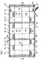
- FIGS. 1 to 4 designated as a whole with 100 hot air dryer serves to dry a surface coating of vehicle bodies 102, which in a front of the hot air dryer 100 arranged coating application section a coating system with a surface coating provided and then by means of a known per se Conveyor 104, for example by means of an inverted circular conveyor, conveyed along a conveying direction 106 through the hot air dryer 100 therethrough become.
- a known per se Conveyor 104 for example by means of an inverted circular conveyor, conveyed along a conveying direction 106 through the hot air dryer 100 therethrough become.
- the hot air dryer 100 comprises an input-side heating area, the comprises at least one heating module 108, as shown in FIGS. 1 to 4 is, and a subsequent to the heating area (not shown) Holding area.
- a heating of the vehicle bodies to be dried takes place 102 to a temperature in the range of about 120 ° C to about 180 ° C, while in the subsequent (not shown) Holding area, the temperature of the vehicle bodies 102 substantially not further increased, but rather is kept substantially constant.
- the heating module 108 is substantially formed cuboid and has a bottom 112, a ceiling wall 114 and two vertical, along the conveying direction 106 extending lateral Outer walls 116 on.
- These outer boundary walls of the heating module 108 are all with a thermal insulation provided to the loss of heat from the interior of the heating module 108 to minimize the environment.
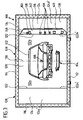
- the interior of the heating module 108 comprises a central tunnel-shaped Trocknernutraum 120, which has a substantially rectangular cross-section has, extends along the conveying direction 106 and on both sides in each case by a vertical partition 122 of a respective lateral air supply channel 124 is disconnected.
- the heating module comprises 108 of the hot air dryer 100 a plurality of first segments 126 and more second segments 128, wherein in the conveying direction 106 each have a second Segment 128 immediately follows a first segment 126 and in each case a first Segment 126 immediately follows a second segment 128.
- the vertical longitudinal center plane 130 of the conveying contour of the vehicle bodies 102 divides each of the segments 126, 128 into a first one Half space 132 a, which extends from the longitudinal center plane 130 (in the conveying direction 106) extends to the right, and into a second half-space 132 b, which extends from the longitudinal center plane 130 (in the conveying direction 106) extends to the left.
- the partition 122b which is arranged in the second half space 132b is formed closed and has no air supply openings.
- the opposite right air supply channel 124a is in the range of the first segment 126 by means of a filter wall 134 into a dryer user space 120 facing nozzle prechamber 136 and the dryer utility room 120 remote pressure channel 138 divided.
- the filter wall 134 has substantially rectangular filter openings, the are closed by filter cartridges 140, which is a substantially rectangular frame with filter material clamped therein.
- first half space 132 a arranged partition wall 122 a of the first Segments 126 are formed air supply openings 146 through which warm Supply air from the nozzle prechamber 136 into the dryer room 120 to flow can.
- a feed nozzle 148 is arranged in each case, through which the dryer supply from the nozzle pre-chamber 136 in the Dryer utility room 120 flows in.
- Each of the feed nozzles 148 has a funnel-shaped inlet region 150, a tubular flow area 152 which is substantially rotationally symmetrical is formed to a nozzle longitudinal axis 154, and a Outlet region 156 which surrounds one of an annular retaining flange Exhaust opening comprises.
- the supply nozzles 148 are fixed to the partition wall 122b so that the air supply openings 146 in the partition wall 122 b with the outlet openings of the Feed nozzles 148 are aligned.
- each feed nozzle 148 defines the mean outflow direction fixed along which the dryer supply through the respective feed nozzle 148 flows out into the dryer utility room 120.
- standard nozzles 158 In a series of feed nozzles 148, hereinafter referred to as standard nozzles 158 are designated, the nozzle longitudinal axis 154 and thus the average outflow direction parallel to the respective surface normal of the vertical Dividing wall 122 a aligned so that the dryer supply through these standard nozzles 158 flows substantially horizontally into the dryer space 120.
- tilt nozzles 160 designated supply nozzles 148, which are arranged on the partition wall 122 a are that the nozzle longitudinal axis 154 and thus the average outflow direction relative to the local surface normal of the partition wall 122a inclined at an angle ⁇ upwards or downwards.
- the vortex-free supply air flow thus obtained covers the entire horizontal Areas of the vehicle bodies to be dried 102 and dissolves only at the edges of these horizontal surfaces of the vehicle bodies from.
- the dryer room 120 a comparatively supply small amount of circulating air.
- the vehicle bodies 102 Due to the vortex-free, laminar supply air flow along the horizontal surfaces
- the vehicle bodies 102 are attached to the vehicle bodies 102 adhering particles are taken along in a particularly efficient manner by the air flow, so that the vehicle bodies 102 are effectively removed from such Particles are cleaned and the extent of the required rework is significantly reduced.
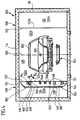
- the in Fig. 3 illustrated second segments 128 of the heating module respectively with respect the longitudinal center plane 130 of the conveying contour of the vehicle bodies 102nd formed mirror-symmetrically to the first segments 126.
- air supply passage 124b ' is by means of a filter wall 134 in a dryer use space 120 facing nozzle prechamber 136 and a dryer use space 120 facing away from the pressure channel 138 divided.
- the filter wall 134 has substantially rectangular filter openings, the are closed by filter cartridges 140, which is a substantially rectangular frame with filter material clamped therein.
- the supply air only from one of the half-spaces on the vehicle bodies 102 to be dried is directed and the partition wall 122 b 'with the feed nozzles 148 opposite Partition 122a 'has no air supply openings, also in the second segments 128 a vortex formation in the central region of Trocknernutraums 120 and thus premature separation of the supply air flow avoided by the horizontal surfaces of the vehicle bodies 102, which has already been mentioned above in connection with the first segment 126 described benefits leads.
- the air extraction shaft is via a filter unit, a heat exchanger and a blower connected to an air supply duct, which in the air supply ducts 124 opens, so that a circulating air flow can be generated, which of the Dryer user room 120 through the air extraction shaft, the filter unit, the Heat exchanger, blower, air supply duct and air supply ducts returns to the dryer room 120, wherein the circulated by means of the blower Air is cleaned through the filter unit and through the heat exchanger is heated.
Landscapes
- Engineering & Computer Science (AREA)
- Mechanical Engineering (AREA)
- General Engineering & Computer Science (AREA)
- Drying Of Solid Materials (AREA)
- Coating Apparatus (AREA)
Applications Claiming Priority (2)
| Application Number | Priority Date | Filing Date | Title |
|---|---|---|---|
| DE10151645A DE10151645A1 (de) | 2001-10-12 | 2001-10-12 | Heisslufttrockner für eine Beschichtungsanlage |
| DE10151645 | 2001-10-12 |
Publications (3)
| Publication Number | Publication Date |
|---|---|
| EP1302737A2 true EP1302737A2 (fr) | 2003-04-16 |
| EP1302737A3 EP1302737A3 (fr) | 2005-10-19 |
| EP1302737B1 EP1302737B1 (fr) | 2008-04-02 |
Family
ID=7703047
Family Applications (1)
| Application Number | Title | Priority Date | Filing Date |
|---|---|---|---|
| EP02022670A Expired - Lifetime EP1302737B1 (fr) | 2001-10-12 | 2002-10-10 | Sécheur à air chaud pour une installation de revêtement |
Country Status (5)
| Country | Link |
|---|---|
| EP (1) | EP1302737B1 (fr) |
| AT (1) | ATE391276T1 (fr) |
| DE (2) | DE10151645A1 (fr) |
| ES (1) | ES2300410T3 (fr) |
| PT (1) | PT1302737E (fr) |
Cited By (9)
| Publication number | Priority date | Publication date | Assignee | Title |
|---|---|---|---|---|
| WO2014111237A1 (fr) * | 2013-01-17 | 2014-07-24 | Eisenmann Ag | Dispositif de régulation de la température d'objets |
| US9228781B2 (en) | 2010-01-26 | 2016-01-05 | Duerr Systems Gmbh | Drying system having a thermal engine |
| DE102015214706A1 (de) | 2015-07-31 | 2017-02-02 | Dürr Systems Ag | Behandlungsanlage und Verfahren zum Behandeln von Werkstücken |
| DE102015214711A1 (de) | 2015-07-31 | 2017-02-02 | Dürr Systems Ag | Behandlungsanlage und Verfahren zum Behandeln von Werkstücken |
| DE102015224916A1 (de) | 2015-12-10 | 2017-06-14 | Dürr Systems Ag | Behandlungsanlage und Verfahren zum Behandeln von Werkstücken |
| DE102015017278B3 (de) | 2015-07-31 | 2019-04-04 | Dürr Systems Ag | Behandlungsanlage und Verfahren zum Behandeln von Werkstücken |
| DE102015017280B3 (de) | 2015-07-31 | 2019-04-04 | Dürr Systems Ag | Behandlungsanlage und Verfahren zum Behandeln von Werkstücken |
| DE102015017279B3 (de) | 2015-07-31 | 2019-04-04 | Dürr Systems Ag | Behandlungsanlage und Verfahren zum Behandeln von Werkstücken |
| EP2775240B1 (fr) | 2013-03-09 | 2019-04-10 | Volkswagen Aktiengesellschaft | Dispositif de traitement d'un revêtement d'une carrosserie de véhicule |
Families Citing this family (2)
| Publication number | Priority date | Publication date | Assignee | Title |
|---|---|---|---|---|
| DE102011076469A1 (de) | 2011-01-26 | 2012-07-26 | Dürr Systems GmbH | Oberflächenbehandlungsvorrichtung und Verfahren zum Betrieb einer Oberflächenbehandlungsvorrichtung |
| CN106907920A (zh) * | 2017-04-28 | 2017-06-30 | 中汽(天津)系统工程有限公司 | 烘干室送风装置 |
Citations (1)
| Publication number | Priority date | Publication date | Assignee | Title |
|---|---|---|---|---|
| DE20104205U1 (de) | 2001-03-12 | 2001-07-19 | Duerr Systems Gmbh | Heißlufttrockner für eine Beschichtungsanlage |
Family Cites Families (4)
| Publication number | Priority date | Publication date | Assignee | Title |
|---|---|---|---|---|
| DE2418358C2 (de) * | 1974-04-16 | 1985-03-21 | Schlechter, Herbert, 5908 Neunkirchen | Vorrichtung zum Trocknen keramischer Produkte |
| DE3941134A1 (de) * | 1989-12-13 | 1991-06-20 | Wagner Max Novokeram | Verfahren und vorrichtung zum trocknen von guetern, insbesondere keramischen formlingen |
| DE19533667C2 (de) * | 1995-09-12 | 2003-08-21 | Keller Hcw Gmbh | Tunneltrockner für keramische Formlinge |
| DE19719183C1 (de) * | 1997-05-06 | 1998-05-28 | Lingl Anlagenbau | Vorrichtung zum Trocknen und Verfahren zum Trocknen von Keramikformlingen |
-
2001
- 2001-10-12 DE DE10151645A patent/DE10151645A1/de not_active Withdrawn
-
2002
- 2002-10-10 ES ES02022670T patent/ES2300410T3/es not_active Expired - Lifetime
- 2002-10-10 DE DE50212006T patent/DE50212006D1/de not_active Expired - Lifetime
- 2002-10-10 PT PT02022670T patent/PT1302737E/pt unknown
- 2002-10-10 AT AT02022670T patent/ATE391276T1/de not_active IP Right Cessation
- 2002-10-10 EP EP02022670A patent/EP1302737B1/fr not_active Expired - Lifetime
Patent Citations (1)
| Publication number | Priority date | Publication date | Assignee | Title |
|---|---|---|---|---|
| DE20104205U1 (de) | 2001-03-12 | 2001-07-19 | Duerr Systems Gmbh | Heißlufttrockner für eine Beschichtungsanlage |
Cited By (33)
| Publication number | Priority date | Publication date | Assignee | Title |
|---|---|---|---|---|
| US9228781B2 (en) | 2010-01-26 | 2016-01-05 | Duerr Systems Gmbh | Drying system having a thermal engine |
| RU2645845C2 (ru) * | 2013-01-17 | 2018-02-28 | Айзенманн Се | Устройство для термостатирования предметов |
| CN104919261A (zh) * | 2013-01-17 | 2015-09-16 | 艾森曼欧洲公司 | 用于物体的调温的装置 |
| WO2014111237A1 (fr) * | 2013-01-17 | 2014-07-24 | Eisenmann Ag | Dispositif de régulation de la température d'objets |
| US10533797B2 (en) | 2013-01-17 | 2020-01-14 | Eisenmann Se | Device for controlling the temperature of objects |
| EP2946158B1 (fr) | 2013-01-17 | 2018-10-10 | Eisenmann SE | Dispositif de régulation de la température d'objets |
| EP2775240B1 (fr) | 2013-03-09 | 2019-04-10 | Volkswagen Aktiengesellschaft | Dispositif de traitement d'un revêtement d'une carrosserie de véhicule |
| US10584920B2 (en) | 2015-07-31 | 2020-03-10 | Dürr Systems Ag | Treatment installation and method for treating workpieces |
| DE202016009019U1 (de) | 2015-07-31 | 2021-07-06 | Dürr Systems Ag | Behandlungsanlage |
| US11740021B2 (en) | 2015-07-31 | 2023-08-29 | Dürr Systems Ag | Treatment installation and method for treating workpieces |
| US11674752B2 (en) | 2015-07-31 | 2023-06-13 | Dürr Systems Ag | Treatment installation and method for treating workpieces |
| DE102015017278B3 (de) | 2015-07-31 | 2019-04-04 | Dürr Systems Ag | Behandlungsanlage und Verfahren zum Behandeln von Werkstücken |
| DE102015017280B3 (de) | 2015-07-31 | 2019-04-04 | Dürr Systems Ag | Behandlungsanlage und Verfahren zum Behandeln von Werkstücken |
| DE102015017279B3 (de) | 2015-07-31 | 2019-04-04 | Dürr Systems Ag | Behandlungsanlage und Verfahren zum Behandeln von Werkstücken |
| WO2017021326A1 (fr) * | 2015-07-31 | 2017-02-09 | Dürr Systems Ag | Installation de traitement et procédé pour traiter des pièces |
| DE102015214711A1 (de) | 2015-07-31 | 2017-02-02 | Dürr Systems Ag | Behandlungsanlage und Verfahren zum Behandeln von Werkstücken |
| DE102015214706A1 (de) | 2015-07-31 | 2017-02-02 | Dürr Systems Ag | Behandlungsanlage und Verfahren zum Behandeln von Werkstücken |
| US10697702B2 (en) | 2015-07-31 | 2020-06-30 | Dürr Systems Ag | Treatment installation and method for treating workpieces |
| EP4141368A1 (fr) | 2015-07-31 | 2023-03-01 | Dürr Systems AG | Installation de traitement et procédé de traitement des pièces |
| EP4036506A2 (fr) | 2015-07-31 | 2022-08-03 | Dürr Systems AG | Installation de traitement et procédé de traitement de pièces |
| US11112177B2 (en) | 2015-07-31 | 2021-09-07 | Dürr Systems Ag | Treatment installation and method for treating workpieces |
| CN107690561A (zh) * | 2015-07-31 | 2018-02-13 | 杜尔系统股份公司 | 处理设备和用于处理工件的方法 |
| RU2742011C2 (ru) * | 2015-07-31 | 2021-02-01 | Дюрр Системс Аг | Обрабатывающая установка и способ обработки заготовок |
| RU2745444C2 (ru) * | 2015-07-31 | 2021-03-25 | Дюрр Системс Аг | Обрабатывающая установка и способ обработки заготовок |
| DE202016009020U1 (de) | 2015-07-31 | 2021-07-06 | Dürr Systems Ag | Behandlungsanlage |
| DE202016009021U1 (de) | 2015-07-31 | 2021-07-06 | Dürr Systems Ag | Behandlungsanlage |
| EP3745066A2 (fr) | 2015-12-10 | 2020-12-02 | Dürr Systems AG | Installation de traitement et procédé de traitement de pièces |
| EP3730885A1 (fr) | 2015-12-10 | 2020-10-28 | Dürr Systems AG | Installation de traitement et procédé de traitement des pièces |
| EP3730884A1 (fr) | 2015-12-10 | 2020-10-28 | Dürr Systems AG | Installation de traitement et procédé de traitement des pièces |
| EP3730886A1 (fr) | 2015-12-10 | 2020-10-28 | Dürr Systems AG | Installation de traitement et procédé de traitement des pièces |
| DE102015224916A1 (de) | 2015-12-10 | 2017-06-14 | Dürr Systems Ag | Behandlungsanlage und Verfahren zum Behandeln von Werkstücken |
| WO2017097483A1 (fr) | 2015-12-10 | 2017-06-15 | Dürr Systems Ag | Installation de traitement et procédé pour traiter des pièces |
| EP4306889A2 (fr) | 2015-12-10 | 2024-01-17 | Dürr Systems AG | Installation de traitement et procédé de traitement des pièces |
Also Published As
| Publication number | Publication date |
|---|---|
| DE50212006D1 (de) | 2008-05-15 |
| EP1302737B1 (fr) | 2008-04-02 |
| DE10151645A1 (de) | 2003-06-18 |
| ES2300410T3 (es) | 2008-06-16 |
| PT1302737E (pt) | 2008-04-17 |
| ATE391276T1 (de) | 2008-04-15 |
| EP1302737A3 (fr) | 2005-10-19 |
Similar Documents
| Publication | Publication Date | Title |
|---|---|---|
| EP0706021B1 (fr) | Séchoir pour une installation de peinture | |
| EP0708905B1 (fr) | Sechoir a air chaud pour secher des surfaces recouvertes d'un revetement | |
| EP1302737A2 (fr) | Sécheur à air chaud pour une installation de revêtement | |
| DE19520179C2 (de) | Kühlschrank | |
| DE10056955A1 (de) | Fahrzeugklimaanlage und Deckenstruktur für ein Fahrzeug mit Klimaanlage | |
| DE19646123A1 (de) | Heiz- oder Klimaanlage für ein Kraftfahrzeug | |
| DE4440044C2 (de) | Klimagerät | |
| EP0658729B2 (fr) | Système de ventilation | |
| DE3909175C2 (fr) | ||
| DE69724627T2 (de) | Deckenmontierte Vorrichtung für Heizung und Kühlung | |
| DE102008013714A1 (de) | Vorrichtung und Verfahren zum Zuführen von Luft zu einem Applikationsbereich einer Lackieranlage | |
| DE102014002419A1 (de) | Fahrzeugklimaanlage | |
| EP1285207A1 (fr) | Systeme de sechage a air chaud pour installation de revetement | |
| DE4007198A1 (de) | Gargeraet | |
| DE102008042803C5 (de) | Vorrichtung zur Führung eines Luftstromes | |
| DE3539718C2 (fr) | ||
| EP2048009B1 (fr) | Agencement de climatisation de véhicule automobile | |
| DE2033195C3 (de) | Luftaustrittseinrichtung für Klimaanlagen | |
| DE19809004B4 (de) | Zuluftvorrichtung | |
| DE19858305C1 (de) | Heißlufttrockner für eine Beschichtungsanlage | |
| DE4009313A1 (de) | Belueftungssystem zum waermebehandeln von flachen materialbahnen | |
| DE19752264C1 (de) | Vorrichtung zur Luftverteilung in einem Fahrzeuginnenraum | |
| DE19951101C1 (de) | Klimaanlage für eine Fahrgastzelle eines Fahrzeugs | |
| EP3702684A1 (fr) | Climatisation des pièces comprenant une amenée d'air frais et thermorégulation | |
| DE3435602A1 (de) | Vorrichtung zur zufuehrung von luft in raeume |
Legal Events
| Date | Code | Title | Description |
|---|---|---|---|
| PUAI | Public reference made under article 153(3) epc to a published international application that has entered the european phase |
Free format text: ORIGINAL CODE: 0009012 |
|
| AK | Designated contracting states |
Designated state(s): AT BE BG CH CY CZ DE DK EE ES FI FR GB GR IE IT LI LU MC NL PT SE SK TR |
|
| AX | Request for extension of the european patent |
Extension state: AL LT LV MK RO SI |
|
| PUAL | Search report despatched |
Free format text: ORIGINAL CODE: 0009013 |
|
| AK | Designated contracting states |
Kind code of ref document: A3 Designated state(s): AT BE BG CH CY CZ DE DK EE ES FI FR GB GR IE IT LI LU MC NL PT SE SK TR |
|
| AX | Request for extension of the european patent |
Extension state: AL LT LV MK RO SI |
|
| RIC1 | Information provided on ipc code assigned before grant |
Ipc: 7F 26B 21/00 B Ipc: 7F 26B 21/02 B Ipc: 7F 26B 15/12 A |
|
| 17P | Request for examination filed |
Effective date: 20051216 |
|
| AKX | Designation fees paid |
Designated state(s): AT BE BG CH CY CZ DE DK EE ES FI FR GB GR IE IT LI LU MC NL PT SE SK TR |
|
| GRAP | Despatch of communication of intention to grant a patent |
Free format text: ORIGINAL CODE: EPIDOSNIGR1 |
|
| GRAS | Grant fee paid |
Free format text: ORIGINAL CODE: EPIDOSNIGR3 |
|
| GRAA | (expected) grant |
Free format text: ORIGINAL CODE: 0009210 |
|
| AK | Designated contracting states |
Kind code of ref document: B1 Designated state(s): AT BE BG CH CY CZ DE DK EE ES FI FR GB GR IE IT LI LU MC NL PT SE SK TR |
|
| REG | Reference to a national code |
Ref country code: GB Ref legal event code: FG4D Free format text: NOT ENGLISH |
|
| REG | Reference to a national code |
Ref country code: PT Ref legal event code: SC4A Free format text: AVAILABILITY OF NATIONAL TRANSLATION Effective date: 20080404 |
|
| REG | Reference to a national code |
Ref country code: IE Ref legal event code: FG4D Free format text: LANGUAGE OF EP DOCUMENT: GERMAN Ref country code: CH Ref legal event code: EP |
|
| GBT | Gb: translation of ep patent filed (gb section 77(6)(a)/1977) |
Effective date: 20080413 |
|
| REF | Corresponds to: |
Ref document number: 50212006 Country of ref document: DE Date of ref document: 20080515 Kind code of ref document: P |
|
| REG | Reference to a national code |
Ref country code: ES Ref legal event code: FG2A Ref document number: 2300410 Country of ref document: ES Kind code of ref document: T3 |
|
| REG | Reference to a national code |
Ref country code: SE Ref legal event code: TRGR |
|
| REG | Reference to a national code |
Ref country code: IE Ref legal event code: FD4D |
|
| PG25 | Lapsed in a contracting state [announced via postgrant information from national office to epo] |
Ref country code: BG Free format text: LAPSE BECAUSE OF FAILURE TO SUBMIT A TRANSLATION OF THE DESCRIPTION OR TO PAY THE FEE WITHIN THE PRESCRIBED TIME-LIMIT Effective date: 20080702 Ref country code: FI Free format text: LAPSE BECAUSE OF FAILURE TO SUBMIT A TRANSLATION OF THE DESCRIPTION OR TO PAY THE FEE WITHIN THE PRESCRIBED TIME-LIMIT Effective date: 20080402 |
|
| ET | Fr: translation filed | ||
| PG25 | Lapsed in a contracting state [announced via postgrant information from national office to epo] |
Ref country code: IE Free format text: LAPSE BECAUSE OF FAILURE TO SUBMIT A TRANSLATION OF THE DESCRIPTION OR TO PAY THE FEE WITHIN THE PRESCRIBED TIME-LIMIT Effective date: 20080402 Ref country code: DK Free format text: LAPSE BECAUSE OF FAILURE TO SUBMIT A TRANSLATION OF THE DESCRIPTION OR TO PAY THE FEE WITHIN THE PRESCRIBED TIME-LIMIT Effective date: 20080402 |
|
| PLBE | No opposition filed within time limit |
Free format text: ORIGINAL CODE: 0009261 |
|
| STAA | Information on the status of an ep patent application or granted ep patent |
Free format text: STATUS: NO OPPOSITION FILED WITHIN TIME LIMIT |
|
| 26N | No opposition filed |
Effective date: 20090106 |
|
| PG25 | Lapsed in a contracting state [announced via postgrant information from national office to epo] |
Ref country code: EE Free format text: LAPSE BECAUSE OF FAILURE TO SUBMIT A TRANSLATION OF THE DESCRIPTION OR TO PAY THE FEE WITHIN THE PRESCRIBED TIME-LIMIT Effective date: 20080402 |
|
| PG25 | Lapsed in a contracting state [announced via postgrant information from national office to epo] |
Ref country code: MC Free format text: LAPSE BECAUSE OF NON-PAYMENT OF DUE FEES Effective date: 20081031 |
|
| REG | Reference to a national code |
Ref country code: CH Ref legal event code: PL |
|
| PG25 | Lapsed in a contracting state [announced via postgrant information from national office to epo] |
Ref country code: CY Free format text: LAPSE BECAUSE OF FAILURE TO SUBMIT A TRANSLATION OF THE DESCRIPTION OR TO PAY THE FEE WITHIN THE PRESCRIBED TIME-LIMIT Effective date: 20080402 |
|
| PG25 | Lapsed in a contracting state [announced via postgrant information from national office to epo] |
Ref country code: LI Free format text: LAPSE BECAUSE OF NON-PAYMENT OF DUE FEES Effective date: 20081031 Ref country code: CH Free format text: LAPSE BECAUSE OF NON-PAYMENT OF DUE FEES Effective date: 20081031 |
|
| PGFP | Annual fee paid to national office [announced via postgrant information from national office to epo] |
Ref country code: CZ Payment date: 20090924 Year of fee payment: 8 Ref country code: PT Payment date: 20090923 Year of fee payment: 8 Ref country code: TR Payment date: 20090923 Year of fee payment: 8 |
|
| PGFP | Annual fee paid to national office [announced via postgrant information from national office to epo] |
Ref country code: AT Payment date: 20091015 Year of fee payment: 8 Ref country code: SE Payment date: 20091014 Year of fee payment: 8 |
|
| PGFP | Annual fee paid to national office [announced via postgrant information from national office to epo] |
Ref country code: NL Payment date: 20091016 Year of fee payment: 8 |
|
| PGFP | Annual fee paid to national office [announced via postgrant information from national office to epo] |
Ref country code: BE Payment date: 20091130 Year of fee payment: 8 |
|
| PG25 | Lapsed in a contracting state [announced via postgrant information from national office to epo] |
Ref country code: LU Free format text: LAPSE BECAUSE OF NON-PAYMENT OF DUE FEES Effective date: 20081010 |
|
| PG25 | Lapsed in a contracting state [announced via postgrant information from national office to epo] |
Ref country code: GR Free format text: LAPSE BECAUSE OF FAILURE TO SUBMIT A TRANSLATION OF THE DESCRIPTION OR TO PAY THE FEE WITHIN THE PRESCRIBED TIME-LIMIT Effective date: 20080703 |
|
| BERE | Be: lapsed |
Owner name: DURR SYSTEMS G.M.B.H. Effective date: 20101031 |
|
| REG | Reference to a national code |
Ref country code: NL Ref legal event code: V1 Effective date: 20110501 |
|
| PG25 | Lapsed in a contracting state [announced via postgrant information from national office to epo] |
Ref country code: CZ Free format text: LAPSE BECAUSE OF NON-PAYMENT OF DUE FEES Effective date: 20101010 Ref country code: PT Free format text: LAPSE BECAUSE OF NON-PAYMENT OF DUE FEES Effective date: 20110411 |
|
| PG25 | Lapsed in a contracting state [announced via postgrant information from national office to epo] |
Ref country code: NL Free format text: LAPSE BECAUSE OF NON-PAYMENT OF DUE FEES Effective date: 20110501 Ref country code: AT Free format text: LAPSE BECAUSE OF NON-PAYMENT OF DUE FEES Effective date: 20101010 Ref country code: BE Free format text: LAPSE BECAUSE OF NON-PAYMENT OF DUE FEES Effective date: 20101031 |
|
| PG25 | Lapsed in a contracting state [announced via postgrant information from national office to epo] |
Ref country code: SE Free format text: LAPSE BECAUSE OF NON-PAYMENT OF DUE FEES Effective date: 20101011 |
|
| PG25 | Lapsed in a contracting state [announced via postgrant information from national office to epo] |
Ref country code: TR Free format text: LAPSE BECAUSE OF NON-PAYMENT OF DUE FEES Effective date: 20101010 |
|
| REG | Reference to a national code |
Ref country code: PT Ref legal event code: MM4A Free format text: LAPSE DUE TO NON-PAYMENT OF FEES Effective date: 20110411 |
|
| REG | Reference to a national code |
Ref country code: DE Ref legal event code: R082 Ref document number: 50212006 Country of ref document: DE Representative=s name: HOEGER, STELLRECHT & PARTNER PATENTANWAELTE MB, DE |
|
| REG | Reference to a national code |
Ref country code: FR Ref legal event code: PLFP Year of fee payment: 14 |
|
| REG | Reference to a national code |
Ref country code: FR Ref legal event code: PLFP Year of fee payment: 15 |
|
| REG | Reference to a national code |
Ref country code: DE Ref legal event code: R082 Ref document number: 50212006 Country of ref document: DE Representative=s name: HOEGER, STELLRECHT & PARTNER PATENTANWAELTE MB, DE Ref country code: DE Ref legal event code: R081 Ref document number: 50212006 Country of ref document: DE Owner name: DUERR SYSTEMS AG, DE Free format text: FORMER OWNER: DUERR SYSTEMS GMBH, 74321 BIETIGHEIM-BISSINGEN, DE |
|
| REG | Reference to a national code |
Ref country code: FR Ref legal event code: PLFP Year of fee payment: 16 |
|
| REG | Reference to a national code |
Ref country code: FR Ref legal event code: PLFP Year of fee payment: 17 |
|
| REG | Reference to a national code |
Ref country code: DE Ref legal event code: R082 Ref document number: 50212006 Country of ref document: DE Representative=s name: HOEGER, STELLRECHT & PARTNER PATENTANWAELTE MB, DE |
|
| PGFP | Annual fee paid to national office [announced via postgrant information from national office to epo] |
Ref country code: FR Payment date: 20201021 Year of fee payment: 19 Ref country code: GB Payment date: 20201022 Year of fee payment: 19 Ref country code: ES Payment date: 20201224 Year of fee payment: 19 |
|
| PGFP | Annual fee paid to national office [announced via postgrant information from national office to epo] |
Ref country code: SK Payment date: 20201007 Year of fee payment: 19 |
|
| PGFP | Annual fee paid to national office [announced via postgrant information from national office to epo] |
Ref country code: DE Payment date: 20211020 Year of fee payment: 20 |
|
| PGFP | Annual fee paid to national office [announced via postgrant information from national office to epo] |
Ref country code: IT Payment date: 20211021 Year of fee payment: 20 |
|
| REG | Reference to a national code |
Ref country code: SK Ref legal event code: MM4A Ref document number: E 3673 Country of ref document: SK Effective date: 20211010 |
|
| GBPC | Gb: european patent ceased through non-payment of renewal fee |
Effective date: 20211010 |
|
| PG25 | Lapsed in a contracting state [announced via postgrant information from national office to epo] |
Ref country code: SK Free format text: LAPSE BECAUSE OF NON-PAYMENT OF DUE FEES Effective date: 20211010 Ref country code: GB Free format text: LAPSE BECAUSE OF NON-PAYMENT OF DUE FEES Effective date: 20211010 |
|
| PG25 | Lapsed in a contracting state [announced via postgrant information from national office to epo] |
Ref country code: FR Free format text: LAPSE BECAUSE OF NON-PAYMENT OF DUE FEES Effective date: 20211031 |
|
| REG | Reference to a national code |
Ref country code: DE Ref legal event code: R071 Ref document number: 50212006 Country of ref document: DE |
|
| REG | Reference to a national code |
Ref country code: ES Ref legal event code: FD2A Effective date: 20230203 |
|
| PG25 | Lapsed in a contracting state [announced via postgrant information from national office to epo] |
Ref country code: ES Free format text: LAPSE BECAUSE OF NON-PAYMENT OF DUE FEES Effective date: 20211011 |