EP1301977B1 - Elektromotor mit rotorbaugruppe und verfahren zur herstellung - Google Patents
Elektromotor mit rotorbaugruppe und verfahren zur herstellung Download PDFInfo
- Publication number
- EP1301977B1 EP1301977B1 EP01971755A EP01971755A EP1301977B1 EP 1301977 B1 EP1301977 B1 EP 1301977B1 EP 01971755 A EP01971755 A EP 01971755A EP 01971755 A EP01971755 A EP 01971755A EP 1301977 B1 EP1301977 B1 EP 1301977B1
- Authority
- EP
- European Patent Office
- Prior art keywords
- sleeve
- stator
- rotor assembly
- rotor
- electric motor
- Prior art date
- Legal status (The legal status is an assumption and is not a legal conclusion. Google has not performed a legal analysis and makes no representation as to the accuracy of the status listed.)
- Expired - Lifetime
Links
Images


Classifications
-
- H—ELECTRICITY
- H02—GENERATION; CONVERSION OR DISTRIBUTION OF ELECTRIC POWER
- H02K—DYNAMO-ELECTRIC MACHINES
- H02K5/00—Casings; Enclosures; Supports
- H02K5/04—Casings or enclosures characterised by the shape, form or construction thereof
- H02K5/12—Casings or enclosures characterised by the shape, form or construction thereof specially adapted for operating in liquid or gas
- H02K5/128—Casings or enclosures characterised by the shape, form or construction thereof specially adapted for operating in liquid or gas using air-gap sleeves or air-gap discs
-
- H—ELECTRICITY
- H02—GENERATION; CONVERSION OR DISTRIBUTION OF ELECTRIC POWER
- H02K—DYNAMO-ELECTRIC MACHINES
- H02K1/00—Details of the magnetic circuit
- H02K1/06—Details of the magnetic circuit characterised by the shape, form or construction
- H02K1/22—Rotating parts of the magnetic circuit
- H02K1/27—Rotor cores with permanent magnets
Definitions
- the invention relates to the field of brushless electric motors Permanent magnets and especially the DC motors, which as so-called internal rotor electric motors are configured.
- Internal rotor motors have a rotor assembly, a rotor shaft and one or more the rotor shaft arranged permanent magnets and in a stator is inserted, which has a stator body and field windings.
- the motor has a housing in which the stator, the Rotor assembly and bearings for the rotatable mounting of the rotor assembly are included.
- the stator includes stator laminations and windings and borders one Interior into which the motor assembly can be inserted.
- the bearings for the rotor assembly in the end caps of the Integrated motor housing, resulting in an overall compact structure becomes.
- a synchronous miniature motor is known, the has a one-piece pot-like housing, which as ferromagnetic effective inference surrounds the ironless field windings and one within of the field windings arranged rotor, whose permanent magnets a sleeve made of magnetically conductive material are arranged.
- the rotor is in a hermetically sealed housing containing the bearings housed, and the torque is output via a Permanent magnet clutch, part of which is by the permanent magnets of the rotor is formed and the other part of a permanent magnet arrangement there is a shaft outside the rotor housing.
- the bearings are permanently lubricated and are against Protected from environmental influences.
- the entire engine is assembled by inserting the hermetically encapsulated rotor into the cylindrical cavity a one-sided open cup-shaped sleeve made of plastic, into which the ironless Field windings are embedded. This sleeve is also in one Pot-shaped housing made of ferromagnetic material.
- DE-PS 32 37 196 has the disadvantage that motors with ironless Field windings due to the large air gap in principle only with one work at low efficiency, which is why they are predominantly used as micromotors for high speeds, preferably in the dental field, are used. For the Delivery of higher torques, such as required for automotive applications, however, they are completely unsuitable.
- the internal rotor motor of DE-PS 32 37 196 has the further disadvantage that the hermetic encapsulation of the rotor assembly is not a direct, mechanical one Coupling a load is possible, but that the torque transmission from the rotor to a shaft only indirectly, e.g. by means of magnetic coupling must, as described in the patent.
- U.S. Patent 4,999,533 describes a motor with an enclosed rotor unit, which is inserted in a press fit in a stator core.
- GB-A-2,186,635 describes a centrifugal pump with a rotor, which is in a cylindrical Component is included, the cylindrical component in a stator core is inserted.
- U.S. patent 3,733,504 known. This document additionally discloses that the sleeve of the rotor assembly can be fixed in the stator with cement. To align the cylindrical component, the stator core has stop edges.
- the invention has for its object a rotor assembly for an electric motor and to provide an internal rotor electric motor, which with low Effort can be assembled, and in which it is ensured that during the Installation and during operation no impurities inside the engine and in particular get into the working air gap.
- the rotor assembly has the advantage that the entire rotor assembly can be pre-assembled in the sleeve, the pre-assembly for example done in a clean room to ensure that no contamination get into the rotor assembly.
- the rotor assembly is preferably like this designed that the rotor shaft is guided out of the sleeve at one end of the sleeve is, the seal between the sleeve body and the rotor shaft via bearings in the front ends of the sleeve, which rotates the rotor shaft to store.
- the sleeve is supported by the bearings, which also have seals Ingress of contaminants are protected, sufficient in their foreheads sealed to prevent the ingress of solid particles. While one end of the sleeve has an opening for leading out the rotor shaft should, the opposite forehead can be completely closed as needed his.
- the sleeve enclosing the rotor is made preferably made of plastic, and the rotor as a whole is preassembled Module inserted into the inside of the stator, so that no problems with the Shearing of ferromagnetic particles can occur.
- the rotor assembly enclosed in the plastic sleeve has the other Advantage that they are when inserted into the stator by the magnetic forces self-centered in the axial direction between the rotor assembly and the stator, so that no further precautions need to be taken, such as providing and Adjusting stops to correctly position the rotor in the stator. It only care must be taken that the rotor assembly in the stator is sufficiently free to move axially so that it cannot be hit by a stop closed end of the stator or the like is prevented from moving in Center the stator magnetically.
- the sleeve for the rotor assembly consists of a Sleeve wall and preferably an additional stiffening structure on the Outside of the sleeve wall. This ensures that the sleeve on the one hand is sufficiently stable, but can also be used if the Working air gap, which is defined by the inner contour of the stator and the outer contour of the Rotors is determined is very small.
- the actual sleeve wall can be thinner than necessary for the stability of the sleeve because of the Stiffening structure gives it additional strength. If a sufficient there is a large air gap, the sleeve wall can also without Stiffening structure to be dimensioned so that it is sufficiently stable.
- the Stiffening structure is preferably formed in the form of ribs in such a way that the outer contour of the stiffening on the outside of the sleeve to the Inner contour of the stator is adapted. On the one hand, this results in a optimal use of the interior of the stator and further the advantage that the rotor assembly can be inserted into the stator without play and without rotation, because the outer contour of the stiffening structure and the inner contour of the stator mesh.
- the rib structure advantageously points in the longitudinal direction of the sleeve or diagonally for this purpose along the outside of the sleeve extending ribs so that the Rotor assembly straight or along a helix through which Guided inner contour of the stator, can be inserted into the stator.
- Bearings for mounting the rotor shaft on this are for easy assembly pre-assembled so that the rotor together with its bearings in the sleeve can be inserted.
- the sleeve essentially has one cylindrical capsule section and a flange section, which together in Intervention can be brought. That the capsule section and the flange section pushed from opposite ends over the rotor shaft and form together a closed housing around the rotor.
- the sleeve is adapted to the shape of the rotor and is generally cylindrical. she can as described in two parts or, for example, three parts with one cylindrical middle part and two end sections.
- the bearings for supporting the shaft preferably come in the front ends of the Sleeve to lie against stops, so that the rotor assembly after Joining the capsule and the flange section sealed in the sleeve is included.
- An internal rotor electric motor is also provided, with a Rotor assembly of the type described and a stator, the The rotor assembly is inserted into the stator and the sleeve has a wall thickness which is equal to or smaller than a working air gap between one Outside diameter of the rotor and an inside diameter of the stator
- the outer contour of the stiffening structure is preferably on the outside of the Sleeve adapted to the inner contour of the stator, the ribs of the Stiffening contour come to lie between the stator poles.
- stator laminations of the stator can be provided with internal grooves the stator poles can be provided with additional stiffening ribs on the Can be brought into engagement outside of the sleeve.
- the rotor assembly is preferably inserted into the stator without play, that the rotor centers itself in the stator pack in the axial direction.
- a rotor assembly for an electric motor and a Internal rotor electric motor in which the rotor together with the bearings in a sleeve is pre-assembled and this rotor assembly is inserted into the stator becomes.
- the rotor shaft is led out of the sleeve, the sleeve wall Adequate sealing together with the bearings and their seals the rotor assembly.
- the sleeve due to the Reinforcement structure are formed very thin-walled, so that this Rotor assembly also for a very small working air gap between the stator and Rotor is suitable.
- the reinforcement structure can be designed so that it is connected to the Inner contour of the stator is adapted and for example with the pole gaps of the Stator comes into engagement.
- the encapsulation of the rotor assembly is preferably carried out with a Plastic-made sleeve so that the rotor when inserted into the Stator centered in the axial direction itself and that no structure-borne noise from the rotor is transmitted to the stator or, if appropriate, a motor housing.
- the rotor assembly includes a rotor shaft 10 which has a yoke ring 12 made of a soft magnetic Material such as iron. On the return ring 12 is a preferred annular permanent magnet 14 attached.
- the shaft 10 is in bearings 16, 18 rotatably supported, the bearings 16, 18 as roller or plain bearings and can be designed in particular as a ball bearing.
- the rotor that goes through here the rotor shaft 10, the yoke ring 12 and the permanent magnet 14 is formed is enclosed in a sleeve 20 which has a capsule section 22 and a flange portion 24 which, with reference to Figures 2-5 are explained in more detail.
- the bearings 16, 18 can be pre-assembled on the rotor shaft 10 and come to lie in the front ends of the sleeve sections 22, 24 and are in this pressed in and / or glued or held in another suitable manner.
- the illustrated embodiment is in the front end of the flange section 24 adjacent to the bearing 18 to compensate for the axial total tolerances annular spring element, e.g. a wave spring ring 26 is provided, via which two bearings 16, 18 can additionally be braced against one another without play.
- the rotor assembly is in Fig. 1 with its basic elements shown, the special dimensioning and precise arrangement of the Elements may vary.
- ball bearings 16, 18 are shown in FIG. 1 provided, the rotor also being rotatable in any other suitable manner can be stored, for example by plain bearings, hydraulic bearings, air bearings etc.
- the rotor assembly can be other than the elements shown exhibit. Between the outer circumference of the permanent magnet 14 and the Inside the sleeve 20, the smallest possible air gap is provided, which Relative movement between the stationary sleeve and the rotating rotor allows.
- the sleeve 20 is preferably made of plastic by injection molding or extrusion manufactured.
- a particularly suitable plastic is LCP (liquid crystal polymer).
- Other materials are polyacetal, polyoxymethylene (POM), polysulfone (PSU), Polycarbonate (PC), polyphenylene sulfide (PPS), polyamideimide (PAi), Polyetheretherketone (PEEK), polyether sulfone (PES), polyetherimide (PEi).
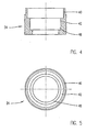
- the sleeve 20 consists of a cup-like Capsule section 22, which is shown in more detail in FIGS. 2 and 3, and one Cover-like flange section 24, which is shown in more detail in FIGS. 4 and 5.
- the capsule section 22 shown in detail in FIGS. 2 and 3 consists of an end wall 32 and an adjoining sleeve part 30 with a relatively thin inner wall.
- Longitudinal ribs 34 are formed, with 18 in the embodiment shown Longitudinal ribs 34 are provided.
- the invention is by no means certain number of ribs is limited as long as a sufficient number of Ribs is provided to give the sleeve 20 the necessary rigidity.
- the longitudinal ribs 34 extend in the substantially over the entire length of the cylindrical sleeve 20 and are parallel aligned with their longitudinal axis.
- the Ribs for example, run diagonally, the number and design of the ribs is adapted to the inner contour of the stator, as with reference to Fig. 6 becomes clear.
- FIG. 6 shows a single stator plate 50 with stator poles 52 and pole gaps 58
- the longitudinal ribs 34 are on the outside of the Capsule section 22 of the sleeve 30 formed and arranged so that this Longitudinal ribs 34 engage with the recesses in pole gaps 58, when the rotor assembly is inserted into the stator.
- ribs can additionally or alternatively do so formed and arranged to engage grooves (not shown) come on the radially inward end faces of the stator poles are arranged.
- the entire rotor assembly are inserted straight into the stator. If you arranged diagonally on the sleeve, for example, the rotor assembly would have to virtually "screwed" into a corresponding stator with inclined pole gaps the stator then out - at a certain angle to each other twisted - stator plates is built up.
- the flange portion 24 of the sleeve 20 is included a relatively short side wall 40 and an end wall 42 formed so that it can be pushed into the capsule section 22.
- the Sleeve sections 22, 24 by means of gluing, welding or other suitable Way to be connected.
- each of the two end walls 32, 42 of the sleeve sections 22, 24 38 and 48 formed into the ball bearings 18, 16 or other suitable bearings can be fitted to support the shaft 10.
- FIG. 7 An embodiment of an internal rotor electric motor according to a preferred Embodiment is shown schematically in FIG. 7.
- the same or Similar elements as in Figs. 1 to 6 are given the same reference numerals referred to and not explained again here.
- FIG. 7 shows the rotor assembly according to FIG. 1 explained with reference to FIG Invention, which is inserted into the interior of a stator 56.
- the stator 56 is in Fig. 7 schematically by a made up of individual stator laminations 50 Laminated core and a winding 60 shown.
- Dashed line 42 indicates the engagement of the longitudinal ribs 34 in the formed between the stator poles 52 Pole gaps 58 at.
- the internal rotor electric motor can be easily are produced by first of all the rotor assembly, preferably in one Clean room, is pre-assembled.
- the iron yoke ring 12 and Permanent magnet 14 applied to the rotor shaft 16 and the bearings 16, 18 the rotor shaft 10 pre-assembled.
- the two sleeve sections 22, 24 are of opposite ends of the shaft 10 pushed over the rotor and interconnected and preferably additionally glued.
- the rotor bearings 16, 18 are then firmly seated in the ends 32, 42 of the sleeve sections 22, 24 and are clamped by the wave spring ring 26
- the wave spring ring 26 Before the fully pre-assembled assembly into the interior of the stator 56 - in which is freely movable axially - pushed in and "self-centering Magnetic forces "aligned in the magnetic center can be permanent Connection to the stator on the outside of the sleeve is preferably a liquid Plastic are applied.
- stator ring is at both ends open so that the axial movement of the rotor assembly is not hindered.
- Other Structures of the stator are recognizable to the person skilled in the art, the invention has the great advantage that on stops or other means for centering of the rotor in the stator can be dispensed with.
- the adhesive fills the gaps still present at least partially and guaranteed after hardening a firm, immovable seat of the rotor in the stator.
- the inner rotor motor constructed in this way can now - without the function in is affected in any way - encapsulated or shed or in an enveloping Housing can be introduced or also arranged with a front Mounting flange are provided.
- stator 56 A special adaptation of the stator 56 to the rotor assembly is not necessary.
- the connections between the individual components, such as shaft 10, yoke ring 12 and permanent magnet 14 or capsule sections 22, 24 and bearings 16, 18 can be made by pressing, gluing, welding, Rest or other suitable way.
- the sleeve 20 and the stator 26 can be glued after joining. To shear off Plastic material of the sleeve 20 when
- the edges of the Permanent magnets 14 may be rounded or chamfered. Numerous others Modifications and modifications of the invention are possible within the scope of the claims.
- the wall thickness of the sleeve part 30 is chosen so that it covers the air gap between the permanent magnets 14 of the rotor and the inside of the stator 56 substantially fills, the inner wall of the sleeve part 30 due to the Rib stiffening can also be thinner than this air gap or the Encapsulated rotor assembly according to the invention even with very little Working air gap can be used.
- the ribs 34 are, as explained, so trained that they are adapted to the inner contour of the stator and with this in Engagement come and that they give the entire sleeve additional rigidity to lend.
- stator 56 In addition to the embodiment shown, it can also be provided Encapsulate stator 56 and cast it in plastic, for example.
Landscapes
- Engineering & Computer Science (AREA)
- Power Engineering (AREA)
- Iron Core Of Rotating Electric Machines (AREA)
- Motor Or Generator Frames (AREA)
- Manufacture Of Motors, Generators (AREA)
- Permanent Field Magnets Of Synchronous Machinery (AREA)
- Permanent Magnet Type Synchronous Machine (AREA)
Applications Claiming Priority (3)
| Application Number | Priority Date | Filing Date | Title |
|---|---|---|---|
| DE10034302 | 2000-07-14 | ||
| DE10034302A DE10034302C2 (de) | 2000-07-14 | 2000-07-14 | Rotorbaugruppe für einen Elektromotor und Innenläufer-Elektromotor |
| PCT/EP2001/007796 WO2002007290A2 (de) | 2000-07-14 | 2001-07-06 | Rotorbaugruppe für einen elektromotor und innenläufer-elektromotor |
Publications (2)
| Publication Number | Publication Date |
|---|---|
| EP1301977A2 EP1301977A2 (de) | 2003-04-16 |
| EP1301977B1 true EP1301977B1 (de) | 2004-10-27 |
Family
ID=7648936
Family Applications (1)
| Application Number | Title | Priority Date | Filing Date |
|---|---|---|---|
| EP01971755A Expired - Lifetime EP1301977B1 (de) | 2000-07-14 | 2001-07-06 | Elektromotor mit rotorbaugruppe und verfahren zur herstellung |
Country Status (9)
| Country | Link |
|---|---|
| US (1) | US6919659B2 (ja) |
| EP (1) | EP1301977B1 (ja) |
| JP (1) | JP2002064965A (ja) |
| KR (1) | KR100517169B1 (ja) |
| CN (1) | CN1213528C (ja) |
| AT (1) | ATE281020T1 (ja) |
| AU (1) | AU2001291663A1 (ja) |
| DE (2) | DE10034302C2 (ja) |
| WO (1) | WO2002007290A2 (ja) |
Families Citing this family (43)
| Publication number | Priority date | Publication date | Assignee | Title |
|---|---|---|---|---|
| DE10051403A1 (de) | 2000-10-17 | 2002-06-13 | Minebea Co Ltd | Rotorbaugruppe für einen Elektromotor und Innenläufer-Elektromotor |
| DE10130130B4 (de) * | 2001-06-22 | 2007-09-20 | Minebea Co., Ltd. | Vorrichtung zur Erzeugung eines drehzahlabhängigen Signals für einen Elektromotor, insbesondere für einen elektronisch kommutierten Gleichstrommotor |
| DE10312869A1 (de) | 2003-03-19 | 2004-10-07 | Minebea Co., Ltd. | Elektromotor |
| DE10324680A1 (de) * | 2003-05-30 | 2004-12-23 | Siemens Ag | Elektrische Maschine mit druckfest gekapseltem Stator |
| SE527802C2 (sv) * | 2004-05-18 | 2006-06-07 | Lind Finance & Dev Ab | Kylning av motor |
| US7095193B2 (en) * | 2004-05-19 | 2006-08-22 | Hr Textron, Inc. | Brushless DC motors with remote Hall sensing and methods of making the same |
| EP1722459B1 (de) * | 2005-05-11 | 2008-03-26 | VDO Automotive AG | Elektrische Maschine mit Abstützung des Rotors auf einer Stirnseite des Stators |
| KR100834221B1 (ko) * | 2006-08-23 | 2008-05-30 | 위아 주식회사 | 직류 모터 |
| EP3144025B1 (en) | 2006-10-24 | 2020-12-30 | ResMed Motor Technologies Inc | Pap device |
| AU2008202487B2 (en) | 2007-06-05 | 2013-07-04 | Resmed Motor Technologies Inc. | Blower with Bearing Tube |
| DE502007005014D1 (de) * | 2007-09-21 | 2010-10-21 | Grundfos Management As | Spaltrohr eines Antriebsmotors für ein Pumpenaggregat |
| DK2108832T3 (en) * | 2008-04-10 | 2016-02-29 | Siemens Ag | Generator and wind turbine |
| DE102008054037B4 (de) * | 2008-10-30 | 2013-05-16 | Bühler Motor GmbH | Geräuscharme Kreiselpumpe |
| DE202008017587U1 (de) | 2008-10-31 | 2010-02-25 | Ms-Schramberg Holding Gmbh & Co. Kg | Rotor |
| US8008820B2 (en) * | 2009-03-16 | 2011-08-30 | Sononwealth Electric Machine Industry Co., Ltd. | Inner-rotor-type motor |
| GB201014074D0 (en) | 2010-08-24 | 2010-10-06 | Dyson Technology Ltd | Rotor for an electrical machine |
| GB201014073D0 (en) * | 2010-08-24 | 2010-10-06 | Dyson Technology Ltd | Rotor core assembly |
| CN102013783B (zh) * | 2010-12-23 | 2012-07-25 | 天津职业技术师范大学 | 一种轻型直流直线电机 |
| SE535812C2 (sv) | 2011-05-17 | 2013-01-02 | Xylem Ip Holdings Llc | Elektrisk motor för en dränkbar maskin |
| DE102011105867A1 (de) * | 2011-06-03 | 2012-12-06 | Minebea Co., Ltd. | Rotor für eine elektrische Maschine |
| CN103199640A (zh) * | 2011-09-09 | 2013-07-10 | 常州新亚电机有限公司 | 一种湿式运行泵用电机以及装配方法 |
| CN102355069B (zh) * | 2011-09-09 | 2013-10-02 | 常州新亚电机有限公司 | 一种湿式运行泵用电机以及装配方法 |
| US10734857B2 (en) | 2011-09-26 | 2020-08-04 | Pangolin Laser Systems, Inc. | Electromechanical limited rotation rotary actuator and method employing segmented coils |
| US9077219B2 (en) * | 2011-09-26 | 2015-07-07 | Pangolin Laser Systems, Inc. | Electromechanical limited rotation rotary actuator |
| US9270144B2 (en) | 2011-09-26 | 2016-02-23 | William R. Benner, Jr. | High torque low inductance rotary actuator |
| US8920142B2 (en) * | 2012-02-28 | 2014-12-30 | Hamilton Sundstrand Corporation | Wet rotor pump motor stator sealing liner |
| US20140001901A1 (en) * | 2012-06-28 | 2014-01-02 | Adam M. Finney | Electric motor with a redundant seal arrangement |
| GB2506970B (en) * | 2012-08-24 | 2020-12-30 | Borgwarner Inc | A shield and coolant guide for an electric machine |
| US9722476B2 (en) | 2013-04-04 | 2017-08-01 | L-3 Communications Cincinnati Electronics Corporation | Self-centering electromagnetic transducers |
| DE102013220495A1 (de) * | 2013-10-10 | 2015-04-16 | Continental Teves Ag & Co. Ohg | Elektrische Maschine |
| DE102015014209A1 (de) | 2015-11-04 | 2016-12-01 | Audi Ag | Verfahren zur Montage einer einen Rotor und einen Stator umfassenden Drehfeldmaschine |
| US10439456B2 (en) * | 2016-04-25 | 2019-10-08 | General Electric Company | Sleeve rotor synchronous reluctance electric machine |
| KR101904871B1 (ko) * | 2017-01-18 | 2018-10-08 | 엘지전자 주식회사 | 베어링카트리지를 구비한 전동기 |
| CN108262151A (zh) * | 2018-01-31 | 2018-07-10 | 湖北环电磁装备工程技术有限公司 | 一种永磁同步电机直驱的圆筒洗矿机 |
| DE102018115952A1 (de) | 2018-07-02 | 2020-01-02 | Ebm-Papst St. Georgen Gmbh & Co. Kg | Motoranordnung mit einem Spalttopf |
| CN110798010B (zh) * | 2018-08-03 | 2021-10-22 | 广东威灵电机制造有限公司 | 电机的定转子组件及电机 |
| DE102018127283A1 (de) * | 2018-10-31 | 2020-04-30 | Eto Magnetic Gmbh | Rotorvorrichtung, Ventil und Verfahren zur Montage einer Rotorvorrichtung |
| EP3671070A1 (en) * | 2018-12-20 | 2020-06-24 | Danfoss A/S | Valve, in particular expansion valve |
| EP3671073A1 (en) * | 2018-12-20 | 2020-06-24 | Danfoss A/S | Electric expansion valve |
| EP3763943A1 (en) * | 2019-07-10 | 2021-01-13 | Grundfos Holding A/S | Method for manufacturing a can |
| DE102019121997B4 (de) * | 2019-08-15 | 2023-05-17 | Vorwerk & Co. Interholding Gmbh | Elektromotor mit Luftspalt-Lagerhülse |
| GB2616284A (en) * | 2022-03-03 | 2023-09-06 | Edwards Ltd | Motor |
| CN117175879B (zh) * | 2023-11-02 | 2024-01-30 | 小米汽车科技有限公司 | 驱动电机的定转子合装机和驱动电机的定转子合装方法 |
Family Cites Families (20)
| Publication number | Priority date | Publication date | Assignee | Title |
|---|---|---|---|---|
| US2782352A (en) * | 1953-05-29 | 1957-02-19 | Hartford Nat Bank & Trust Co | Alternating-current motor |
| US2875694A (en) * | 1954-09-08 | 1959-03-03 | Fostoria Pressed Steel Corp | Motor driven pumps |
| US3138105A (en) * | 1961-02-08 | 1964-06-23 | Fostoria Corp | Motor driven pumps |
| CH385565A (de) | 1961-07-10 | 1964-12-15 | Bbc Brown Boveri & Cie | Gasgeschmiertes Gleitlager |
| US3733504A (en) * | 1971-07-27 | 1973-05-15 | Harowe Servo Controls Inc | Self supporting rotary electrical device |
| US4118644A (en) * | 1974-10-12 | 1978-10-03 | Firma Schulte Elektrotechnik Kg | Electrical machinery |
| US4017964A (en) * | 1974-10-12 | 1977-04-19 | Firma Schulte Elektrotechnik Kg | Method of manufacturing electrical machinery having a rotor |
| US4017946A (en) * | 1976-03-01 | 1977-04-19 | Alta Engineering, Inc. | Lock screw for rigging connector or the like |
| US4564780A (en) * | 1983-03-14 | 1986-01-14 | Eastway Holdings Limited | Electrical machine having a quickly releasable stator |
| GB2186635B (en) * | 1986-02-18 | 1990-01-31 | Easthorpe Investments Ltd | Centrifugal pump particularly for domestic appliances such as washing machines,dishwashers,and the like |
| US4999533A (en) * | 1989-09-07 | 1991-03-12 | A. O. Smith Corporation | Dynamoelectric machine |
| US5667309A (en) * | 1994-11-15 | 1997-09-16 | Sankyo Seiki Mfg. Co., Ltd. | Bearing seal system |
| JPH10196646A (ja) | 1996-12-27 | 1998-07-31 | Sankyo Seiki Mfg Co Ltd | 動圧軸受装置 |
| US6296391B1 (en) * | 1997-06-09 | 2001-10-02 | Sankyo Seiki Mfg. Co., Ltd. | Hydrodynamic bearing apparatus |
| AU8291098A (en) * | 1997-07-09 | 1999-02-08 | Sl Montevideo Technology, Inc. | Brushless dc permanent magnet motors for traction drive systems |
| JP3318531B2 (ja) * | 1998-08-04 | 2002-08-26 | ミネベア株式会社 | 回転電機及びその軸受構造 |
| US6150747A (en) * | 1999-05-04 | 2000-11-21 | Electric Boat Corporation | Composite stator and rotor for an electric motor |
| JP4232278B2 (ja) | 1999-06-25 | 2009-03-04 | パナソニック株式会社 | 動圧軸受及びそれを搭載したスピンドルモータ |
| JP4481475B2 (ja) * | 2000-11-02 | 2010-06-16 | 東北リコー株式会社 | 動圧型軸受ユニット |
| JP2002188635A (ja) | 2000-12-21 | 2002-07-05 | Nsk Ltd | 流体軸受装置 |
-
2000
- 2000-07-14 DE DE10034302A patent/DE10034302C2/de not_active Expired - Lifetime
-
2001
- 2001-07-06 DE DE50104312T patent/DE50104312D1/de not_active Expired - Fee Related
- 2001-07-06 EP EP01971755A patent/EP1301977B1/de not_active Expired - Lifetime
- 2001-07-06 AU AU2001291663A patent/AU2001291663A1/en not_active Abandoned
- 2001-07-06 JP JP2001206547A patent/JP2002064965A/ja not_active Withdrawn
- 2001-07-06 WO PCT/EP2001/007796 patent/WO2002007290A2/de active IP Right Grant
- 2001-07-06 KR KR10-2002-7018071A patent/KR100517169B1/ko not_active IP Right Cessation
- 2001-07-06 CN CNB018126936A patent/CN1213528C/zh not_active Expired - Fee Related
- 2001-07-06 US US10/332,872 patent/US6919659B2/en not_active Expired - Lifetime
- 2001-07-06 AT AT01971755T patent/ATE281020T1/de not_active IP Right Cessation
Also Published As
| Publication number | Publication date |
|---|---|
| CN1213528C (zh) | 2005-08-03 |
| DE50104312D1 (de) | 2004-12-02 |
| EP1301977A2 (de) | 2003-04-16 |
| ATE281020T1 (de) | 2004-11-15 |
| US20030178903A1 (en) | 2003-09-25 |
| WO2002007290A2 (de) | 2002-01-24 |
| DE10034302A1 (de) | 2002-02-21 |
| CN1441986A (zh) | 2003-09-10 |
| JP2002064965A (ja) | 2002-02-28 |
| DE10034302C2 (de) | 2002-06-13 |
| KR20030019477A (ko) | 2003-03-06 |
| KR100517169B1 (ko) | 2005-09-26 |
| AU2001291663A1 (en) | 2002-01-30 |
| WO2002007290A3 (de) | 2002-07-18 |
| US6919659B2 (en) | 2005-07-19 |
Similar Documents
| Publication | Publication Date | Title |
|---|---|---|
| EP1301977B1 (de) | Elektromotor mit rotorbaugruppe und verfahren zur herstellung | |
| EP1329014B1 (de) | Rotorbaugruppe für einen elektromotor und innenläufer-elektromotor | |
| EP2398130B1 (de) | Elektrokleinmotor | |
| DE69737869T2 (de) | Getriebemotor, insbesondere zum Antrieb von Zubehörteilen in Kraftfahrzeugen | |
| DE102008026648B4 (de) | Rotor für einen elektronisch kommutierten Elektromotor, Verfahren zur Herstellung eines solchen Rotors sowie bei der Herstellung eines solchen Rotors verwendbares Zwischenprodukt | |
| DE2433770A1 (de) | Elektrische maschine | |
| DE10152151A1 (de) | Permanentmagnetrotor | |
| WO2019138068A1 (de) | Motorisiertes antriebssystem, verwendung des antriebssystems zur betätigung einer tür, herstellungsverfahren für ein antriebssystem | |
| EP2891236B1 (de) | Elektrische maschine zum motorischen verstellen beweglicher teile im kraftfahrzeug, sowie verfahren zum herstellen der elektrischen maschine | |
| EP3593441A1 (de) | Elektromotor | |
| DE19954966A1 (de) | Elektrische Antriebseinheit | |
| DE102008054330A1 (de) | Zweiteiliges Motorgehäuse mit Bajonett-Verbindung | |
| WO2004042891A1 (de) | Permanentmagnetmaschine mit axialem luftspal | |
| EP1664470B1 (de) | Antriebssystem für verstelleinrichtungen in kraftfahrzeugen | |
| DE102022103482A1 (de) | Drehantriebsvorrichtung | |
| DE102006059135A1 (de) | Elektrische Maschine | |
| EP0250405B1 (de) | Magnetkörper für motorbremsen | |
| DE102013105964A1 (de) | Rotor mit Lagereinrichtung | |
| EP4046258A1 (de) | Elektrische stelleinheit | |
| DE102011054955A1 (de) | Rotorbaugruppe eines Gleichstrommotors | |
| DE102017105089A1 (de) | Elektromotor | |
| EP1563587B1 (de) | Antriebsvorrichtung für verstelleinrichtungen in kraftfahrzeugen | |
| EP0410488B1 (de) | Antriebseinheit mit einem Elektromotor | |
| DE102022100369B3 (de) | Elektromotor zum Antrieb einer Fahrzeugklappe, Verwendung und Verfahren zur Herstellung des Elektromotors | |
| EP3035497A1 (de) | Karusselltür |
Legal Events
| Date | Code | Title | Description |
|---|---|---|---|
| PUAI | Public reference made under article 153(3) epc to a published international application that has entered the european phase |
Free format text: ORIGINAL CODE: 0009012 |
|
| 17P | Request for examination filed |
Effective date: 20021216 |
|
| AK | Designated contracting states |
Designated state(s): AT BE CH CY DE DK ES FI FR GB GR IE IT LI LU MC NL PT SE TR |
|
| AX | Request for extension of the european patent |
Extension state: AL LT LV MK RO SI |
|
| RAP1 | Party data changed (applicant data changed or rights of an application transferred) |
Owner name: MINEBEA CO., LTD. |
|
| GRAP | Despatch of communication of intention to grant a patent |
Free format text: ORIGINAL CODE: EPIDOSNIGR1 |
|
| RTI1 | Title (correction) |
Free format text: ELECTRIC MOTOR WITH ROTOR ASSEMBLY AND METHOD OF MANUFACTURING |
|
| RTI1 | Title (correction) |
Free format text: ELECTRIC MOTOR WITH ROTOR ASSEMBLY AND METHOD OF MANUFACTURING |
|
| RTI1 | Title (correction) |
Free format text: ELECTRIC MOTOR WITH ROTOR ASSEMBLY AND METHOD OF MANUFACTURING |
|
| GRAS | Grant fee paid |
Free format text: ORIGINAL CODE: EPIDOSNIGR3 |
|
| GRAA | (expected) grant |
Free format text: ORIGINAL CODE: 0009210 |
|
| AK | Designated contracting states |
Kind code of ref document: B1 Designated state(s): AT BE CH CY DE DK ES FI FR GB GR IE IT LI LU MC NL PT SE TR |
|
| PG25 | Lapsed in a contracting state [announced via postgrant information from national office to epo] |
Ref country code: TR Free format text: LAPSE BECAUSE OF FAILURE TO SUBMIT A TRANSLATION OF THE DESCRIPTION OR TO PAY THE FEE WITHIN THE PRESCRIBED TIME-LIMIT Effective date: 20041027 Ref country code: FI Free format text: LAPSE BECAUSE OF FAILURE TO SUBMIT A TRANSLATION OF THE DESCRIPTION OR TO PAY THE FEE WITHIN THE PRESCRIBED TIME-LIMIT Effective date: 20041027 Ref country code: IE Free format text: LAPSE BECAUSE OF FAILURE TO SUBMIT A TRANSLATION OF THE DESCRIPTION OR TO PAY THE FEE WITHIN THE PRESCRIBED TIME-LIMIT Effective date: 20041027 Ref country code: GB Free format text: LAPSE BECAUSE OF FAILURE TO SUBMIT A TRANSLATION OF THE DESCRIPTION OR TO PAY THE FEE WITHIN THE PRESCRIBED TIME-LIMIT Effective date: 20041027 Ref country code: NL Free format text: LAPSE BECAUSE OF FAILURE TO SUBMIT A TRANSLATION OF THE DESCRIPTION OR TO PAY THE FEE WITHIN THE PRESCRIBED TIME-LIMIT Effective date: 20041027 |
|
| REG | Reference to a national code |
Ref country code: GB Ref legal event code: FG4D Free format text: NOT ENGLISH |
|
| REG | Reference to a national code |
Ref country code: CH Ref legal event code: EP |
|
| REG | Reference to a national code |
Ref country code: IE Ref legal event code: FG4D Free format text: GERMAN |
|
| REF | Corresponds to: |
Ref document number: 50104312 Country of ref document: DE Date of ref document: 20041202 Kind code of ref document: P |
|
| PG25 | Lapsed in a contracting state [announced via postgrant information from national office to epo] |
Ref country code: SE Free format text: LAPSE BECAUSE OF FAILURE TO SUBMIT A TRANSLATION OF THE DESCRIPTION OR TO PAY THE FEE WITHIN THE PRESCRIBED TIME-LIMIT Effective date: 20050127 Ref country code: GR Free format text: LAPSE BECAUSE OF FAILURE TO SUBMIT A TRANSLATION OF THE DESCRIPTION OR TO PAY THE FEE WITHIN THE PRESCRIBED TIME-LIMIT Effective date: 20050127 Ref country code: DK Free format text: LAPSE BECAUSE OF FAILURE TO SUBMIT A TRANSLATION OF THE DESCRIPTION OR TO PAY THE FEE WITHIN THE PRESCRIBED TIME-LIMIT Effective date: 20050127 |
|
| PG25 | Lapsed in a contracting state [announced via postgrant information from national office to epo] |
Ref country code: ES Free format text: LAPSE BECAUSE OF FAILURE TO SUBMIT A TRANSLATION OF THE DESCRIPTION OR TO PAY THE FEE WITHIN THE PRESCRIBED TIME-LIMIT Effective date: 20050207 |
|
| LTIE | Lt: invalidation of european patent or patent extension |
Effective date: 20041027 |
|
| NLV1 | Nl: lapsed or annulled due to failure to fulfill the requirements of art. 29p and 29m of the patents act | ||
| REG | Reference to a national code |
Ref country code: IE Ref legal event code: FD4D |
|
| GBV | Gb: ep patent (uk) treated as always having been void in accordance with gb section 77(7)/1977 [no translation filed] |
Effective date: 20041027 |
|
| ET | Fr: translation filed | ||
| PG25 | Lapsed in a contracting state [announced via postgrant information from national office to epo] |
Ref country code: AT Free format text: LAPSE BECAUSE OF NON-PAYMENT OF DUE FEES Effective date: 20050706 Ref country code: LU Free format text: LAPSE BECAUSE OF NON-PAYMENT OF DUE FEES Effective date: 20050706 Ref country code: CY Free format text: LAPSE BECAUSE OF FAILURE TO SUBMIT A TRANSLATION OF THE DESCRIPTION OR TO PAY THE FEE WITHIN THE PRESCRIBED TIME-LIMIT Effective date: 20050706 |
|
| PG25 | Lapsed in a contracting state [announced via postgrant information from national office to epo] |
Ref country code: BE Free format text: LAPSE BECAUSE OF NON-PAYMENT OF DUE FEES Effective date: 20050731 Ref country code: LI Free format text: LAPSE BECAUSE OF NON-PAYMENT OF DUE FEES Effective date: 20050731 Ref country code: CH Free format text: LAPSE BECAUSE OF NON-PAYMENT OF DUE FEES Effective date: 20050731 Ref country code: MC Free format text: LAPSE BECAUSE OF NON-PAYMENT OF DUE FEES Effective date: 20050731 |
|
| PLBE | No opposition filed within time limit |
Free format text: ORIGINAL CODE: 0009261 |
|
| STAA | Information on the status of an ep patent application or granted ep patent |
Free format text: STATUS: NO OPPOSITION FILED WITHIN TIME LIMIT |
|
| 26N | No opposition filed |
Effective date: 20050728 |
|
| PG25 | Lapsed in a contracting state [announced via postgrant information from national office to epo] |
Ref country code: DE Free format text: LAPSE BECAUSE OF NON-PAYMENT OF DUE FEES Effective date: 20060201 |
|
| REG | Reference to a national code |
Ref country code: CH Ref legal event code: PL |
|
| BERE | Be: lapsed |
Owner name: *MINEBEA CO. LTD Effective date: 20050731 |
|
| PG25 | Lapsed in a contracting state [announced via postgrant information from national office to epo] |
Ref country code: PT Free format text: LAPSE BECAUSE OF NON-PAYMENT OF DUE FEES Effective date: 20050327 |
|
| PGFP | Annual fee paid to national office [announced via postgrant information from national office to epo] |
Ref country code: IT Payment date: 20070730 Year of fee payment: 7 |
|
| PGFP | Annual fee paid to national office [announced via postgrant information from national office to epo] |
Ref country code: FR Payment date: 20070710 Year of fee payment: 7 |
|
| REG | Reference to a national code |
Ref country code: FR Ref legal event code: ST Effective date: 20090331 |
|
| PG25 | Lapsed in a contracting state [announced via postgrant information from national office to epo] |
Ref country code: FR Free format text: LAPSE BECAUSE OF NON-PAYMENT OF DUE FEES Effective date: 20080731 Ref country code: IT Free format text: LAPSE BECAUSE OF NON-PAYMENT OF DUE FEES Effective date: 20080706 |