US6150747A - Composite stator and rotor for an electric motor - Google Patents
Composite stator and rotor for an electric motor Download PDFInfo
- Publication number
- US6150747A US6150747A US09/304,804 US30480499A US6150747A US 6150747 A US6150747 A US 6150747A US 30480499 A US30480499 A US 30480499A US 6150747 A US6150747 A US 6150747A
- Authority
- US
- United States
- Prior art keywords
- resin material
- lamination assembly
- composite
- disk
- ring member
- Prior art date
- Legal status (The legal status is an assumption and is not a legal conclusion. Google has not performed a legal analysis and makes no representation as to the accuracy of the status listed.)
- Expired - Lifetime
Links
Images

Classifications
-
- H—ELECTRICITY
- H02—GENERATION; CONVERSION OR DISTRIBUTION OF ELECTRIC POWER
- H02K—DYNAMO-ELECTRIC MACHINES
- H02K1/00—Details of the magnetic circuit
- H02K1/06—Details of the magnetic circuit characterised by the shape, form or construction
- H02K1/12—Stationary parts of the magnetic circuit
- H02K1/18—Means for mounting or fastening magnetic stationary parts on to, or to, the stator structures
- H02K1/185—Means for mounting or fastening magnetic stationary parts on to, or to, the stator structures to outer stators
-
- H—ELECTRICITY
- H02—GENERATION; CONVERSION OR DISTRIBUTION OF ELECTRIC POWER
- H02K—DYNAMO-ELECTRIC MACHINES
- H02K1/00—Details of the magnetic circuit
- H02K1/06—Details of the magnetic circuit characterised by the shape, form or construction
- H02K1/22—Rotating parts of the magnetic circuit
- H02K1/28—Means for mounting or fastening rotating magnetic parts on to, or to, the rotor structures
-
- H—ELECTRICITY
- H02—GENERATION; CONVERSION OR DISTRIBUTION OF ELECTRIC POWER
- H02K—DYNAMO-ELECTRIC MACHINES
- H02K5/00—Casings; Enclosures; Supports
- H02K5/04—Casings or enclosures characterised by the shape, form or construction thereof
- H02K5/12—Casings or enclosures characterised by the shape, form or construction thereof specially adapted for operating in liquid or gas
- H02K5/128—Casings or enclosures characterised by the shape, form or construction thereof specially adapted for operating in liquid or gas using air-gap sleeves or air-gap discs
Definitions
- This invention relates to stators and rotors for electric motors having reduced weight and improved corrosion resistance.
- Conventional stators and rotors for electric motors are typically made from machined, cast or forged metals including steel. To provide corrosion resistance metal alloys are frequently used. In many instances it is important not only to improve the corrosion resistance but also to reduce the weight of the stators and rotors in an electric motor.
- the Brown U.S. Pat. Nos. 4,729,160 and 4,930,201 disclose a rotor having a plurality of magnets bonded to a rotor hub and a composite sleeve disposed over the rotor hub and magnets.
- the Tassinario U.S. Pat. No. 4,879,485 discloses a permanent magnet rotor containing a stack of circular sheets of magnetic material mounted on a shaft and an array of permanent magnets adhesively bonded to the periphery of the stack of sheets, the magnets having inwardly inclined adjacent edges forming V-shaped openings.
- 4,433,261 to Nashiki, et al. discloses a rotor having a plurality of magnet sectors mounted on a shaft which are axially displaced with respect to each other and side plates of non-magnetic metal having recesses to receive the displaced magnet ends.
- the periphery of the rotor has a layer of non-magnetic fiber such as glass fiber, carbon fiber or the like, secured with a resin.
- the Trago et al. U.S. Pat. No. 5,806,169 discloses an injection molded motor assembly including a stator assembled from a series of laminations having a plurality of teeth forming the stator poles and surrounded by windings which is then pressure filled with molten plastic to seal the assembly.
- U.S. Pat. No. 5,502,341 to Sato likewise discloses a stator assembled from laminated plates and having a resin-impregnated inner peripheral surface.
- a stator assembly has a laminated stator core which receives stator coils and outer and inner cylinders enclosing the stator laminations and coils, along with end covers and a resin filling encapsulating the coils and laminations.
- Another object of the invention is to provide stator and rotor arrangements for electric motors which have reduced weight and increased corrosion resistance.
- a composite rotor arrangement having a metal hub and a disk made of a resin material mounted on the hub and surrounded by a thin-walled band of non-magnetic material along with a circumferential array of laminations containing magnet units on the outer surface of the non-magnetic band which is, in turn, enclosed by an outer wrap of composite material to encapsulate the array of laminations and magnet units.
- the magnet units may be either permanent magnets or coil windings.
- Suitable resin materials include but are not limited to composites made from resin with or without high strength, high modulus fibers such as fiberglass, graphite, carbon, boron, quartz and aramid fibers, i.e., aromatic polyamide fibers, which have high temperature resistance, flame resistance and electrical resistance properties.
- high modulus fibers such as fiberglass, graphite, carbon, boron, quartz and aramid fibers, i.e., aromatic polyamide fibers, which have high temperature resistance, flame resistance and electrical resistance properties.
- a composite stator arrangement in accordance with the invention includes a composite outer ring retained between stator caps and surrounding a flanged inner composite ring containing a thin-walled steel band with an array of laminations and windings disposed inside the steel band and encapsulated by an outer wrap of resin material.
- a lightweight corrosion-resistant motor includes both the composite stator arrangement and the composite rotor arrangement of the invention.
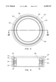
- FIG. 1 is a side view of a composite rotor arrangement in accordance with the invention
- FIG. 2 is a cross sectional view of the rotor arrangement shown in FIG. 1 taken along the line II--II of FIG. 1 and looking in the direction of the arrows;
- FIG. 3 is a side view of a composite stator arrangement in accordance with the invention.
- FIG. 4 is a cross sectional view of the stator arrangement of FIG. 3 taken along the line IV--IV of FIG. 3 and looking in the direction of the arrows.
- a steel hub 12 having a central opening 14 to receive an axial mounting shaft carries a composite disk 16 consisting of inner and outer annular members 18 and 20, respectively, connected by four radial arms 22 which are separated by open spaces 24.
- the disk 16 has a projecting flange 30 extending radially outwardly from one edge of the disk providing a recessed portion 32.
- the periphery of the disk 16 within the recessed portion 32 is surrounded by a non-ferromagnetic steel band 34 and surrounding the non-ferromagnetic band 34 is a magnet array including a plurality of circular laminations 38 in which an array of magnet units 40 is mounted.
- the magnet units may be constituted either by permanent magnets or by coil windings which are energized to produce corresponding magnetic poles.
- An outer wrap 42 of composite material encloses the array of laminations and magnet units as well as the steel band 34.
- the composite resin material used to make the disk 16 and the outer wrap 42 is preferably a high strength resin containing high modulus fibers such as fiberglass, graphite, carbon, boron, quartz, or aramid fiber material.
- the composite disk 16 may be molded in substantially final form or machined from a blank made of the resin composition.
- FIGS. 3 and 4 illustrate a composite stator arrangement 50 in accordance with the invention which includes a motor frame 52 and a lamination and coil assembly 54 affixed to the motor frame 52 and retained therein by two stator caps 56.
- the lamination and coil assembly 54 includes coil windings 58 which produce the magnetic poles of the stator when energized and laminations 60, mounted in an outer composite ring 62 which is clamped between the stator caps 56 when the assembly is mounted in the motor frame 52.
- a steel band 64 surrounds the laminations 60 and the coil windings 58 which are received on corresponding segments of the laminations 60.
- the lamination and coil assembly 54 and the steel band 64 are mounted on a flanged inner composite ring 66 and then encapsulated in an inner composite wrap 68 to provide resistance to corrosion. Thereafter the encapsulated lamination and coil assembly is affixed to the outer composite ring 62 and mounted by the stator caps 56 to the motor frame 52.
- the material of the composite resin components of the stator arrangement is preferably a high strength resin with or without high strength, high modulus fibers such as fiberglass, graphite, carbon, boron, quartz and aramid fibers, producing good high temperature resistance, flame resistance and electrical resistance, as well as protecting the enclosed metallic parts from corrosion.
- An electric motor containing a composite stator arrangement and a composite rotor arrangement according to the invention has a reduced overall weight and provides improved corrosion resistance when operated in a corrosive environment.
Abstract
In the embodiments described in the specification, a stator for an electric motor has an outer ring member made of resin material and supported from a frame by stator caps and a flanged inner composite ring member made of resin material which receives a steel band. Laminations and coil windings are mounted inside the steel band and an outer wrap of resin material encapsulates the steel band, laminations and coil windings. A rotor arrangement includes a steel hub surrounded by a disk-shaped member made of resin material and having inner and outer rings connected by radial arms. A non-ferromagnetic steel band surrounds the peripheral surface of the disk-shaped member and laminations and magnets or coil windings are positioned on the band and are encapsulated by an outer wrap of resin material.
Description
This invention relates to stators and rotors for electric motors having reduced weight and improved corrosion resistance.
Conventional stators and rotors for electric motors are typically made from machined, cast or forged metals including steel. To provide corrosion resistance metal alloys are frequently used. In many instances it is important not only to improve the corrosion resistance but also to reduce the weight of the stators and rotors in an electric motor.
The Brown U.S. Pat. Nos. 4,729,160 and 4,930,201 disclose a rotor having a plurality of magnets bonded to a rotor hub and a composite sleeve disposed over the rotor hub and magnets. The Tassinario U.S. Pat. No. 4,879,485 discloses a permanent magnet rotor containing a stack of circular sheets of magnetic material mounted on a shaft and an array of permanent magnets adhesively bonded to the periphery of the stack of sheets, the magnets having inwardly inclined adjacent edges forming V-shaped openings. Carbon or glass fibers are wound through the V-shaped openings provided by the magnets to retain the magnets in place and a resin is applied over the threads in each opening to provide a continuous cylindrical surface. The El-Antably et al. U.S. Pat. No. 5,296,773 describes a rotor assembly consisting of a plurality of axial laminations alternately containing magnetic and non-magnetic material with an end cap at each axial end which engages stepped axial ends of the laminations, the outermost lamination on the rotor being a composite material with a carbon fiber center and a fiberglass outer layer. U.S. Pat. No. 4,433,261 to Nashiki, et al., discloses a rotor having a plurality of magnet sectors mounted on a shaft which are axially displaced with respect to each other and side plates of non-magnetic metal having recesses to receive the displaced magnet ends. The periphery of the rotor has a layer of non-magnetic fiber such as glass fiber, carbon fiber or the like, secured with a resin.
The Trago et al. U.S. Pat. No. 5,806,169 discloses an injection molded motor assembly including a stator assembled from a series of laminations having a plurality of teeth forming the stator poles and surrounded by windings which is then pressure filled with molten plastic to seal the assembly. U.S. Pat. No. 5,502,341 to Sato likewise discloses a stator assembled from laminated plates and having a resin-impregnated inner peripheral surface. In the Fukushi et al. U.S. Pat. No. 4,492,889, a stator assembly has a laminated stator core which receives stator coils and outer and inner cylinders enclosing the stator laminations and coils, along with end covers and a resin filling encapsulating the coils and laminations.
Accordingly, it is an object of the present invention to provide composite stator and rotor arrangements for electric motors which overcome disadvantages of the prior art.
Another object of the invention is to provide stator and rotor arrangements for electric motors which have reduced weight and increased corrosion resistance.
These and other objects of the invention are attained by providing a composite rotor arrangement having a metal hub and a disk made of a resin material mounted on the hub and surrounded by a thin-walled band of non-magnetic material along with a circumferential array of laminations containing magnet units on the outer surface of the non-magnetic band which is, in turn, enclosed by an outer wrap of composite material to encapsulate the array of laminations and magnet units. The magnet units may be either permanent magnets or coil windings. Suitable resin materials include but are not limited to composites made from resin with or without high strength, high modulus fibers such as fiberglass, graphite, carbon, boron, quartz and aramid fibers, i.e., aromatic polyamide fibers, which have high temperature resistance, flame resistance and electrical resistance properties.
A composite stator arrangement in accordance with the invention includes a composite outer ring retained between stator caps and surrounding a flanged inner composite ring containing a thin-walled steel band with an array of laminations and windings disposed inside the steel band and encapsulated by an outer wrap of resin material. A lightweight corrosion-resistant motor includes both the composite stator arrangement and the composite rotor arrangement of the invention.
Further objects and advantages of the invention will be apparent from reading of the following description in conjunction with the accompanying drawings in which:
FIG. 1 is a side view of a composite rotor arrangement in accordance with the invention;
FIG. 2 is a cross sectional view of the rotor arrangement shown in FIG. 1 taken along the line II--II of FIG. 1 and looking in the direction of the arrows;
FIG. 3 is a side view of a composite stator arrangement in accordance with the invention; and
FIG. 4 is a cross sectional view of the stator arrangement of FIG. 3 taken along the line IV--IV of FIG. 3 and looking in the direction of the arrows.
In the typical embodiment of a composite rotor arrangement 10 illustrated in FIGS. 1 and 2, a steel hub 12 having a central opening 14 to receive an axial mounting shaft carries a composite disk 16 consisting of inner and outer annular members 18 and 20, respectively, connected by four radial arms 22 which are separated by open spaces 24. As best seen in FIG. 2, the disk 16 has a projecting flange 30 extending radially outwardly from one edge of the disk providing a recessed portion 32. The periphery of the disk 16 within the recessed portion 32 is surrounded by a non-ferromagnetic steel band 34 and surrounding the non-ferromagnetic band 34 is a magnet array including a plurality of circular laminations 38 in which an array of magnet units 40 is mounted. The magnet units may be constituted either by permanent magnets or by coil windings which are energized to produce corresponding magnetic poles. An outer wrap 42 of composite material encloses the array of laminations and magnet units as well as the steel band 34.
To provide the necessary strength as well as resistance to corrosive materials and relatively low weight, the composite resin material used to make the disk 16 and the outer wrap 42 is preferably a high strength resin containing high modulus fibers such as fiberglass, graphite, carbon, boron, quartz, or aramid fiber material. The composite disk 16 may be molded in substantially final form or machined from a blank made of the resin composition.
With this composite rotor arrangement, structural integrity and rigidity of the rotor is assured while providing a light-weight structure having improved resistance to corrosion.
FIGS. 3 and 4 illustrate a composite stator arrangement 50 in accordance with the invention which includes a motor frame 52 and a lamination and coil assembly 54 affixed to the motor frame 52 and retained therein by two stator caps 56. The lamination and coil assembly 54 includes coil windings 58 which produce the magnetic poles of the stator when energized and laminations 60, mounted in an outer composite ring 62 which is clamped between the stator caps 56 when the assembly is mounted in the motor frame 52.
In addition, a steel band 64 surrounds the laminations 60 and the coil windings 58 which are received on corresponding segments of the laminations 60. The lamination and coil assembly 54 and the steel band 64 are mounted on a flanged inner composite ring 66 and then encapsulated in an inner composite wrap 68 to provide resistance to corrosion. Thereafter the encapsulated lamination and coil assembly is affixed to the outer composite ring 62 and mounted by the stator caps 56 to the motor frame 52.
As in the composite rotor arrangement described above, the material of the composite resin components of the stator arrangement is preferably a high strength resin with or without high strength, high modulus fibers such as fiberglass, graphite, carbon, boron, quartz and aramid fibers, producing good high temperature resistance, flame resistance and electrical resistance, as well as protecting the enclosed metallic parts from corrosion.
An electric motor containing a composite stator arrangement and a composite rotor arrangement according to the invention has a reduced overall weight and provides improved corrosion resistance when operated in a corrosive environment.
Although the invention has been described herein with reference to specific embodiments, many modifications and variations therein will readily occur to those skilled in the art. Accordingly, all such variations and modifications are included within the intended scope of the claims.
Claims (17)
1. A composite stator arrangement for an electric motor comprising an outer ring member containing a resin material and having a cylindrical opening, a motor frame member containing resin material surrounding the outer ring member, circular stator caps disposed on opposite sides of the outer ring member for clamping the outer ring member to the motor frame member, a toroidal coil and lamination assembly comprising a plurality of coil windings mounted on core laminations distributed about the periphery of the cylindrical opening, a flanged inner ring member containing resin material in which the coil and lamination assembly is mounted, a steel band surrounding the coil and lamination assembly and an outer wrap containing resin material and encapsulating the coil and lamination assembly.
2. A composite stator arrangement according to claim 1 wherein at least one of the outer ring member, the flanged inner ring member and the outer wrap comprises a high strength resin material containing high strength, high modulus fibers.
3. A composite stator arrangement according to claim 2 wherein the high strength, high modulus fibers are selected from the group consisting of fiberglass, graphite, carbon, boron, quartz and aramid fibers.
4. A composite stator arrangement according to claim 1 wherein the steel band is in the flanged inner ring member extending around the lamination assembly and is encapsulated by the outer wrap.
5. A composite rotor arrangement comprising a central hub member having an axial passage for receipt of a rotor shaft, a disk-shaped member containing resin material mounted on the central hub member having an outer peripheral surface, an array of laminations containing magnet units mounted on the outer peripheral surface of the disk-shaped member, a non-ferromagnetic steel band on an outer peripheral surface of the disc-shaped member beneath the array of laminations and an outer wrap containing resin material and encapsulating the array of laminations and magnet units.
6. A composite rotor arrangement according to claim 5 wherein at least one of the disk-shaped member and the outer wrap comprises a high strength resin material containing high strength, high modulus fibers.
7. A composite rotor arrangement according to claim 6 wherein the high strength, high modulus fibers are selected from the group consisting of fiberglass, graphite, carbon, boron, quartz and aramid fibers.
8. A composite rotor arrangement according to claim 5 wherein the disk-shaped member has a peripheral flange extending radially outwardly and the array of laminations is mounted in a recess formed by an outer peripheral surface of the disk and the peripheral flange.
9. A composite rotor arrangement according to claim 5, wherein the disk-shaped member includes inner and outer rings joined by radial arms which are separated by open spaces.
10. A composite rotor arrangement according to claim 5, wherein the magnet units comprise permanent magnets.
11. A composite rotor arrangement according to claim 5, wherein the magnet units comprise coil windings. ring member containing resin material in which the toroidal coil and the lamination assembly is mounted and an outer stator wrap enclosing the coil and the lamination assembly, and a composite rotor arrangement rotatably supported within the opening of the composite stator arrangement comprising a hub, a disk-shaped member mounted on the hub containing a resin material, a lamination assembly containing magnet units mounted on the periphery of the disk-shaped member, and an outer rotor wrap containing resin material and encapsulating the lamination assembly containing magnetic units.
12. An electric motor comprising a stator arrangement including an outer ring member containing resin material and having a cylindrical opening, a toroidal coil and lamination assembly mounted within the cylindrical opening, a flanged inner ring member containing resin material in which the toroidal coil and the lamination assembly is mounted and an outer stator wrap enclosing the coil and the lamination assembly, and a composite rotor arrangement rotatably supported within the opening of the composite stator arrangement comprising a hub, a disk-shaped member mounted on the hub containing a resin material, a lamination assembly containing magnet units mounted on the periphery of the disk-shaped member, a non-ferromagnetic steel band on the outer peripheral surface of the disc-shaped member beneath the lamination assembly and an outer rotor wrap containing resin material and encapsulating the lamination assembly containing magnetic units.
13. An electric motor according to claim 12 wherein the toroidal coil and lamination assembly is affixed to the outer ring member by circular stator caps.
14. An electric motor according to claim 12 wherein at least one of the outer ring member, the flanged inner ring member, the outer stator wrap, the disk-shaped member and the outer rotor wrap comprises a high strength resin material containing high strength, high modulus fibers.
15. An electric motor according to claim 14 wherein the high strength, high modulus fibers are selected from the group consisting of fiberglass, graphite, carbon, boron, quartz and aramid fibers.
16. An electric motor according to claim 12 including a steel band in the flanged inner ring member extending around the lamination assembly and encapsulated by the outer wrap.
17. An electric motor according to claim 12 wherein the disk-shaped member includes inner and outer rings joined by radial arms which are separated by open spaces.
Priority Applications (3)
| Application Number | Priority Date | Filing Date | Title |
|---|---|---|---|
| US09/304,804 US6150747A (en) | 1999-05-04 | 1999-05-04 | Composite stator and rotor for an electric motor |
| EP00200574A EP1050946A3 (en) | 1999-05-04 | 2000-02-21 | Composite stator and rotor for an electric motor |
| JP2000135241A JP2000333387A (en) | 1999-05-04 | 2000-05-08 | Stator and rotor in motor |
Applications Claiming Priority (1)
| Application Number | Priority Date | Filing Date | Title |
|---|---|---|---|
| US09/304,804 US6150747A (en) | 1999-05-04 | 1999-05-04 | Composite stator and rotor for an electric motor |
Publications (1)
| Publication Number | Publication Date |
|---|---|
| US6150747A true US6150747A (en) | 2000-11-21 |
Family
ID=23178101
Family Applications (1)
| Application Number | Title | Priority Date | Filing Date |
|---|---|---|---|
| US09/304,804 Expired - Lifetime US6150747A (en) | 1999-05-04 | 1999-05-04 | Composite stator and rotor for an electric motor |
Country Status (3)
| Country | Link |
|---|---|
| US (1) | US6150747A (en) |
| EP (1) | EP1050946A3 (en) |
| JP (1) | JP2000333387A (en) |
Cited By (25)
| Publication number | Priority date | Publication date | Assignee | Title |
|---|---|---|---|---|
| US20030048020A1 (en) * | 2001-09-07 | 2003-03-13 | G.E. Tornquist | Exciter rotor assembly |
| US20030146670A1 (en) * | 2002-02-04 | 2003-08-07 | Pieter Van Dine | Composite lamina arrangement for canning of motors |
| US20030178903A1 (en) * | 2000-07-14 | 2003-09-25 | Harald Rapp | Rotor assembly for an electric motor and electric motor with internal rotor |
| US20030222514A1 (en) * | 2002-05-29 | 2003-12-04 | Pieter Van Dine | Encapsulated permanent magnet motor rotor |
| US20040086380A1 (en) * | 2001-02-13 | 2004-05-06 | Honeywell International Inc. | Face seal assembly with composite stator |
| US20060022541A1 (en) * | 2004-07-30 | 2006-02-02 | Raymond Ong | Rotor hub and assembly for a permanent magnet power electric machine |
| US20060043811A1 (en) * | 2004-07-30 | 2006-03-02 | Raymond Ong | Rotor assembly for a permanent magnet power electric machine |
| US20060097595A1 (en) * | 2004-10-05 | 2006-05-11 | Alstom Transport Sa | Rotor for an electric motor and corresponding electric motor |
| US20070276074A1 (en) * | 2004-03-23 | 2007-11-29 | Piet Van Dine | Fire-resistant structural composite material |
| US20080088195A1 (en) * | 2006-10-16 | 2008-04-17 | Dooley Kevin A | Outside rotor electric machine |
| DE102009043224A1 (en) * | 2009-09-28 | 2011-03-31 | Siemens Aktiengesellschaft | Rotor for electrical machine, has magnet bags, permanent magnet and core, where permanent magnets are positioned in magnet bags |
| US20110121672A1 (en) * | 2008-05-12 | 2011-05-26 | Magnomatics Limited | Magnetic pole-piece support |
| US20110127859A1 (en) * | 2008-07-14 | 2011-06-02 | Hanning Electro-Werke GmbH & Co. KG | Permanent-magnetic rotor |
| US20120068565A1 (en) * | 2009-03-25 | 2012-03-22 | Eagleburgmann Germany Gmbh & Co. Kg | Thermally decoupled bearing arrangement |
| US20130064704A1 (en) * | 2010-05-20 | 2013-03-14 | Advics Co., Ltd. | Rotation device including seal structure |
| US20130069450A1 (en) * | 2011-09-16 | 2013-03-21 | Persimmon Technologies, Corp. | Robot Drive With Passive Rotor |
| US20130162068A1 (en) * | 2011-12-22 | 2013-06-27 | Black & Decker Inc. | Overmolded stator assembly lamination stack for a power tool |
| US20140300245A1 (en) * | 2013-04-09 | 2014-10-09 | Mitsubishi Electric Corporation | Stator-core fixing structure for rotating electric machine |
| US20160268857A1 (en) * | 2014-03-13 | 2016-09-15 | Canrig Drilling Technology Ltd. | Low Inertia Direct Drive Drawworks |
| US9627937B2 (en) | 2013-12-02 | 2017-04-18 | GM Global Technology Operations LLC | Stator for an electric motor |
| US20190036384A1 (en) * | 2015-03-05 | 2019-01-31 | Arburg Gmbh + Co Kg | Rotor for an electric motor, associated motor shaft, and method for producing said motor shaft and rotor |
| DE102017121215A1 (en) * | 2017-09-13 | 2019-03-14 | Valeo Systèmes d'Essuyage | Brushless electric motor |
| US20190084402A1 (en) * | 2017-09-21 | 2019-03-21 | Schaeffler Technologies AG & Co. KG | Hybrid motor vehicle drive train including hybrid module baffle blade |
| US10476354B2 (en) | 2011-09-16 | 2019-11-12 | Persimmon Technologies Corp. | Robot drive with isolated optical encoder |
| US11476728B2 (en) | 2021-01-15 | 2022-10-18 | Ge Aviation Systems Llc | Electric machine having a containment band |
Families Citing this family (9)
| Publication number | Priority date | Publication date | Assignee | Title |
|---|---|---|---|---|
| KR100653434B1 (en) | 2005-04-29 | 2006-12-01 | 영 춘 정 | Brushless DC motor |
| US8299661B2 (en) * | 2007-05-11 | 2012-10-30 | Sntech Inc. | Rotor of brushless motor |
| US8033007B2 (en) | 2007-05-11 | 2011-10-11 | Sntech, Inc. | Method of making rotor of brushless motor |
| JP2010534459A (en) * | 2007-07-24 | 2010-11-04 | パワー グループ インターナショナル インコーポレイテッド | Apparatus and method for clamping and locking permanent magnets and using tilted concentrated flux magnets to improve cooling in rotating electrical machines |
| ES2431593T3 (en) * | 2008-04-10 | 2013-11-27 | Siemens Aktiengesellschaft | Stator, generator and wind turbine layout |
| JP6282795B2 (en) * | 2011-11-10 | 2018-02-21 | 日本電産株式会社 | motor |
| US10436204B2 (en) | 2014-05-30 | 2019-10-08 | Abb Schweiz Ag | Fan assembly for cooling electric machine and electric machine incorporating same |
| KR101862214B1 (en) * | 2017-07-27 | 2018-05-29 | 주식회사 에스플러스컴텍 | BLDC motor using nanomaterial-based polymer compound |
| KR101919976B1 (en) * | 2018-05-21 | 2018-11-19 | 주식회사 에스플러스컴텍 | Bldc motor using nanomaterial-based polymer compound |
Citations (36)
| Publication number | Priority date | Publication date | Assignee | Title |
|---|---|---|---|---|
| US2650992A (en) * | 1952-01-10 | 1953-09-01 | Oster John Mfg Co | End bell assembly for dynamo-electric machines |
| US2668925A (en) * | 1949-04-05 | 1954-02-09 | Kearfott Company Inc | Electric machine construction |
| US2887454A (en) * | 1952-11-28 | 1959-05-19 | Ohio Commw Eng Co | Light weight magnet and method of making |
| US2896100A (en) * | 1957-12-09 | 1959-07-21 | Gen Electric | Electrodynamic machine |
| US3132270A (en) * | 1959-09-29 | 1964-05-05 | Phelon Co Inc | Rotor annulus for electric generator |
| US3683216A (en) * | 1971-02-24 | 1972-08-08 | Richard F Post | Inertial energy storage apparatus and system for utilizing the same |
| US3873861A (en) * | 1973-06-15 | 1975-03-25 | Richard Halm | Electric motor, especially a squirrel-cage motor |
| US3919572A (en) * | 1973-12-26 | 1975-11-11 | Rotron Inc | Electrical motor construction |
| US4150582A (en) * | 1976-08-02 | 1979-04-24 | Electric Power Research Institute, Inc. | Rotor ring for inertial energy storage rotor |
| US4433261A (en) * | 1982-03-24 | 1984-02-21 | Kabushiki Kaisha Okuma Tekkosho | Rotor for permanent magnet type synchronous motors |
| US4492889A (en) * | 1982-11-19 | 1985-01-08 | Hitachi, Ltd. | Stator of submerged motor |
| US4661183A (en) * | 1985-10-22 | 1987-04-28 | Vernay Laboratories, Inc. | Method for making and applying rotor bands |
| US4729160A (en) * | 1985-08-14 | 1988-03-08 | Kollmorgen Technologies Corporation | Method for manufacturing a composite sleeve for an electric motor |
| US4777397A (en) * | 1986-08-15 | 1988-10-11 | Marathon Electric Manufacturing Corp. | Permanent magnet generator apparatus including a consequent pole rotor |
| US4870310A (en) * | 1988-03-02 | 1989-09-26 | Triplett Billy R | Portable crash-survivable kinetic energy storage machine |
| US4879485A (en) * | 1987-09-16 | 1989-11-07 | Mavilor Systemes S.A. | Permanent magnet rotor |
| US4930201A (en) * | 1985-08-14 | 1990-06-05 | Kollmorgen Corporation | Method for manufacturing a composite sleeve for an electric motor |
| US4954736A (en) * | 1988-04-25 | 1990-09-04 | Matsushita Electric Works, Ltd. | Permanent magnet rotor with magnets secured by synthetic resin |
| US5122704A (en) * | 1990-10-25 | 1992-06-16 | Sundstrand Corporation | Composite rotor sleeve |
| US5124605A (en) * | 1991-01-11 | 1992-06-23 | American Flywheel Systems, Inc. | Flywheel-based energy storage methods and apparatus |
| US5265323A (en) * | 1989-02-28 | 1993-11-30 | E. I. Du Pont De Nemours And Company | Method of fabricating a stator assembly for a non-static cogging brushless DC motor |
| US5296773A (en) * | 1993-04-20 | 1994-03-22 | General Motors Corporation | Composite rotor for a synchronous reluctance machine |
| US5349257A (en) * | 1993-04-06 | 1994-09-20 | Sundstrand Corporation | Permanent magnet generator with a position sensing coil |
| US5422528A (en) * | 1992-12-09 | 1995-06-06 | Robert Bosch Gmbh | Drum commutator for electrical machines |
| US5502341A (en) * | 1991-05-20 | 1996-03-26 | Sanyo Electric Co., Ltd. | Electric motor and method of producing the same |
| US5525852A (en) * | 1993-04-05 | 1996-06-11 | General Electric Company | Banded electromagnetic stator core |
| US5585682A (en) * | 1993-11-10 | 1996-12-17 | Sundstrand Corporation | Thermally compensated assembly for a generator |
| US5717263A (en) * | 1993-07-06 | 1998-02-10 | British Nuclear Fuels Plc | Rotors |
| US5736804A (en) * | 1994-02-10 | 1998-04-07 | Comtrade Handelsgesellschaft Mbh | Reinforcement ring for rotating bodies and method of producing the same |
| US5760508A (en) * | 1993-07-06 | 1998-06-02 | British Nuclear Fuels Plc | Energy storage and conversion devices |
| US5760506A (en) * | 1995-06-07 | 1998-06-02 | The Boeing Company | Flywheels for energy storage |
| US5806169A (en) * | 1995-04-03 | 1998-09-15 | Trago; Bradley A. | Method of fabricating an injected molded motor assembly |
| US5811900A (en) * | 1996-05-02 | 1998-09-22 | Chrysler Corporation | Segmented rim construction for a rotor |
| US5821650A (en) * | 1996-05-02 | 1998-10-13 | Chrysler Corporation | Soft magnet for a rotor |
| US5828152A (en) * | 1995-02-07 | 1998-10-27 | Denyo Kabushiki Kaisha | Rotor with permanent magnet of generator and method of manufacturing the same |
| US5936320A (en) * | 1995-05-29 | 1999-08-10 | Denyo Kabushiki Kaisha | Engine-driven permanent magnetic type welding generator |
Family Cites Families (7)
| Publication number | Priority date | Publication date | Assignee | Title |
|---|---|---|---|---|
| CH511531A (en) * | 1969-07-04 | 1971-08-15 | Sulzer Ag | Electrical device with at least one stationary electrical winding |
| FR2087126A5 (en) * | 1970-05-05 | 1971-12-31 | Brissonneau & Lotz | |
| US4883982A (en) * | 1988-06-02 | 1989-11-28 | General Electric Company | Electronically commutated motor, blower integral therewith, and stationary and rotatable assemblies therefor |
| US4973872A (en) * | 1988-10-07 | 1990-11-27 | Emerson Electric Co. | Dynamoelectric machine rotor assembly with improved magnet retention stucture |
| WO1993008632A1 (en) * | 1991-10-25 | 1993-04-29 | Filmlab Engineering Pty Limited | A magnetically coupled motor |
| CH692881A5 (en) * | 1992-12-23 | 2002-11-29 | Cp Pumpen Ag | Magnetic coupling. |
| EP0854558A3 (en) * | 1997-01-21 | 2000-07-12 | Isuzu Ceramics Research Institute Co., Ltd. | Structure of a rotor for generators and method of manufacturing the same rotor |
-
1999
- 1999-05-04 US US09/304,804 patent/US6150747A/en not_active Expired - Lifetime
-
2000
- 2000-02-21 EP EP00200574A patent/EP1050946A3/en not_active Withdrawn
- 2000-05-08 JP JP2000135241A patent/JP2000333387A/en not_active Withdrawn
Patent Citations (36)
| Publication number | Priority date | Publication date | Assignee | Title |
|---|---|---|---|---|
| US2668925A (en) * | 1949-04-05 | 1954-02-09 | Kearfott Company Inc | Electric machine construction |
| US2650992A (en) * | 1952-01-10 | 1953-09-01 | Oster John Mfg Co | End bell assembly for dynamo-electric machines |
| US2887454A (en) * | 1952-11-28 | 1959-05-19 | Ohio Commw Eng Co | Light weight magnet and method of making |
| US2896100A (en) * | 1957-12-09 | 1959-07-21 | Gen Electric | Electrodynamic machine |
| US3132270A (en) * | 1959-09-29 | 1964-05-05 | Phelon Co Inc | Rotor annulus for electric generator |
| US3683216A (en) * | 1971-02-24 | 1972-08-08 | Richard F Post | Inertial energy storage apparatus and system for utilizing the same |
| US3873861A (en) * | 1973-06-15 | 1975-03-25 | Richard Halm | Electric motor, especially a squirrel-cage motor |
| US3919572A (en) * | 1973-12-26 | 1975-11-11 | Rotron Inc | Electrical motor construction |
| US4150582A (en) * | 1976-08-02 | 1979-04-24 | Electric Power Research Institute, Inc. | Rotor ring for inertial energy storage rotor |
| US4433261A (en) * | 1982-03-24 | 1984-02-21 | Kabushiki Kaisha Okuma Tekkosho | Rotor for permanent magnet type synchronous motors |
| US4492889A (en) * | 1982-11-19 | 1985-01-08 | Hitachi, Ltd. | Stator of submerged motor |
| US4729160A (en) * | 1985-08-14 | 1988-03-08 | Kollmorgen Technologies Corporation | Method for manufacturing a composite sleeve for an electric motor |
| US4930201A (en) * | 1985-08-14 | 1990-06-05 | Kollmorgen Corporation | Method for manufacturing a composite sleeve for an electric motor |
| US4661183A (en) * | 1985-10-22 | 1987-04-28 | Vernay Laboratories, Inc. | Method for making and applying rotor bands |
| US4777397A (en) * | 1986-08-15 | 1988-10-11 | Marathon Electric Manufacturing Corp. | Permanent magnet generator apparatus including a consequent pole rotor |
| US4879485A (en) * | 1987-09-16 | 1989-11-07 | Mavilor Systemes S.A. | Permanent magnet rotor |
| US4870310A (en) * | 1988-03-02 | 1989-09-26 | Triplett Billy R | Portable crash-survivable kinetic energy storage machine |
| US4954736A (en) * | 1988-04-25 | 1990-09-04 | Matsushita Electric Works, Ltd. | Permanent magnet rotor with magnets secured by synthetic resin |
| US5265323A (en) * | 1989-02-28 | 1993-11-30 | E. I. Du Pont De Nemours And Company | Method of fabricating a stator assembly for a non-static cogging brushless DC motor |
| US5122704A (en) * | 1990-10-25 | 1992-06-16 | Sundstrand Corporation | Composite rotor sleeve |
| US5124605A (en) * | 1991-01-11 | 1992-06-23 | American Flywheel Systems, Inc. | Flywheel-based energy storage methods and apparatus |
| US5502341A (en) * | 1991-05-20 | 1996-03-26 | Sanyo Electric Co., Ltd. | Electric motor and method of producing the same |
| US5422528A (en) * | 1992-12-09 | 1995-06-06 | Robert Bosch Gmbh | Drum commutator for electrical machines |
| US5525852A (en) * | 1993-04-05 | 1996-06-11 | General Electric Company | Banded electromagnetic stator core |
| US5349257A (en) * | 1993-04-06 | 1994-09-20 | Sundstrand Corporation | Permanent magnet generator with a position sensing coil |
| US5296773A (en) * | 1993-04-20 | 1994-03-22 | General Motors Corporation | Composite rotor for a synchronous reluctance machine |
| US5760508A (en) * | 1993-07-06 | 1998-06-02 | British Nuclear Fuels Plc | Energy storage and conversion devices |
| US5717263A (en) * | 1993-07-06 | 1998-02-10 | British Nuclear Fuels Plc | Rotors |
| US5585682A (en) * | 1993-11-10 | 1996-12-17 | Sundstrand Corporation | Thermally compensated assembly for a generator |
| US5736804A (en) * | 1994-02-10 | 1998-04-07 | Comtrade Handelsgesellschaft Mbh | Reinforcement ring for rotating bodies and method of producing the same |
| US5828152A (en) * | 1995-02-07 | 1998-10-27 | Denyo Kabushiki Kaisha | Rotor with permanent magnet of generator and method of manufacturing the same |
| US5806169A (en) * | 1995-04-03 | 1998-09-15 | Trago; Bradley A. | Method of fabricating an injected molded motor assembly |
| US5936320A (en) * | 1995-05-29 | 1999-08-10 | Denyo Kabushiki Kaisha | Engine-driven permanent magnetic type welding generator |
| US5760506A (en) * | 1995-06-07 | 1998-06-02 | The Boeing Company | Flywheels for energy storage |
| US5811900A (en) * | 1996-05-02 | 1998-09-22 | Chrysler Corporation | Segmented rim construction for a rotor |
| US5821650A (en) * | 1996-05-02 | 1998-10-13 | Chrysler Corporation | Soft magnet for a rotor |
Cited By (50)
| Publication number | Priority date | Publication date | Assignee | Title |
|---|---|---|---|---|
| US20030178903A1 (en) * | 2000-07-14 | 2003-09-25 | Harald Rapp | Rotor assembly for an electric motor and electric motor with internal rotor |
| US6919659B2 (en) * | 2000-07-14 | 2005-07-19 | Minebea Co., Ltd. | Rotor assembly for an electric motor and electric motor with internal rotor |
| US20040086380A1 (en) * | 2001-02-13 | 2004-05-06 | Honeywell International Inc. | Face seal assembly with composite stator |
| US6918594B2 (en) | 2001-02-13 | 2005-07-19 | Honeywell International, Inc. | Face seal assembly with composite stator |
| US7086137B2 (en) * | 2001-09-07 | 2006-08-08 | Honeywell International, Inc. | Rotor assembly method |
| US6753637B2 (en) * | 2001-09-07 | 2004-06-22 | Honeywell International, Inc. | Exciter rotor assembly |
| US20040168301A1 (en) * | 2001-09-07 | 2004-09-02 | G.E. Tornquist | Exciter rotor assembly |
| US20030048020A1 (en) * | 2001-09-07 | 2003-03-13 | G.E. Tornquist | Exciter rotor assembly |
| US20030146670A1 (en) * | 2002-02-04 | 2003-08-07 | Pieter Van Dine | Composite lamina arrangement for canning of motors |
| US6963151B2 (en) * | 2002-02-04 | 2005-11-08 | Electric Boat Corporation | Composite lamina arrangement for canning of motors |
| US20030222514A1 (en) * | 2002-05-29 | 2003-12-04 | Pieter Van Dine | Encapsulated permanent magnet motor rotor |
| US6847145B2 (en) * | 2002-05-29 | 2005-01-25 | Electric Boat Corporation | Encapsulated permanent magnet motor rotor |
| US7323509B2 (en) | 2004-03-23 | 2008-01-29 | General Dynamics Armament And Technical Products, Inc. | Fire-resistant structural composite material |
| US20070276074A1 (en) * | 2004-03-23 | 2007-11-29 | Piet Van Dine | Fire-resistant structural composite material |
| US20060043811A1 (en) * | 2004-07-30 | 2006-03-02 | Raymond Ong | Rotor assembly for a permanent magnet power electric machine |
| US7098569B2 (en) | 2004-07-30 | 2006-08-29 | Ballard Power Systems Corporation | Rotor assembly for a permanent magnet power electric machine |
| US20070273232A1 (en) * | 2004-07-30 | 2007-11-29 | Raymond Ong | Rotor hub and assembly for a permanent magnet power electric machine |
| US20060022541A1 (en) * | 2004-07-30 | 2006-02-02 | Raymond Ong | Rotor hub and assembly for a permanent magnet power electric machine |
| US20060097595A1 (en) * | 2004-10-05 | 2006-05-11 | Alstom Transport Sa | Rotor for an electric motor and corresponding electric motor |
| US20080088195A1 (en) * | 2006-10-16 | 2008-04-17 | Dooley Kevin A | Outside rotor electric machine |
| US9425655B2 (en) * | 2008-05-12 | 2016-08-23 | Magnomatics Limited | Magnetic pole-piece support |
| US20110121672A1 (en) * | 2008-05-12 | 2011-05-26 | Magnomatics Limited | Magnetic pole-piece support |
| US20110133594A1 (en) * | 2008-05-12 | 2011-06-09 | Magnomatics Limited | Magnetic pole-piece structure |
| US9099895B2 (en) * | 2008-05-12 | 2015-08-04 | Magnomatics Limited | Magnetic pole-piece structure |
| US20110127859A1 (en) * | 2008-07-14 | 2011-06-02 | Hanning Electro-Werke GmbH & Co. KG | Permanent-magnetic rotor |
| US8519588B2 (en) * | 2008-07-14 | 2013-08-27 | Hanning Elektro-Werke Gmbh & Co. Kg | Permanent-magnetic rotor |
| US20120068565A1 (en) * | 2009-03-25 | 2012-03-22 | Eagleburgmann Germany Gmbh & Co. Kg | Thermally decoupled bearing arrangement |
| DE102009043224A1 (en) * | 2009-09-28 | 2011-03-31 | Siemens Aktiengesellschaft | Rotor for electrical machine, has magnet bags, permanent magnet and core, where permanent magnets are positioned in magnet bags |
| US8992194B2 (en) * | 2010-05-20 | 2015-03-31 | Advics Co., Ltd. | Rotation device including seal structure |
| US20130064704A1 (en) * | 2010-05-20 | 2013-03-14 | Advics Co., Ltd. | Rotation device including seal structure |
| US9800114B2 (en) | 2011-09-16 | 2017-10-24 | Persimmon Technologies Corporation | Robot drive with radially adjustable sensor connection |
| US10476354B2 (en) | 2011-09-16 | 2019-11-12 | Persimmon Technologies Corp. | Robot drive with isolated optical encoder |
| US8716909B2 (en) | 2011-09-16 | 2014-05-06 | Persimmon Technologies, Corp. | Robot with heat dissipating stator |
| US20130069450A1 (en) * | 2011-09-16 | 2013-03-21 | Persimmon Technologies, Corp. | Robot Drive With Passive Rotor |
| US11469649B2 (en) | 2011-09-16 | 2022-10-11 | Persimmon Technologies Corporation | Robot drive with isolated optical encoder |
| US10020704B2 (en) | 2011-09-16 | 2018-07-10 | Persimmon Technologies Corporation | Electrical connection through motor housing |
| US11031850B2 (en) | 2011-09-16 | 2021-06-08 | Persimmon Technologies Corporation | Robot drive with isolated optical encoder |
| US20130162068A1 (en) * | 2011-12-22 | 2013-06-27 | Black & Decker Inc. | Overmolded stator assembly lamination stack for a power tool |
| US9300174B2 (en) * | 2013-04-09 | 2016-03-29 | Mitsubishi Electric Corporation | Stator-core fixing structure for rotating electric machine |
| US20140300245A1 (en) * | 2013-04-09 | 2014-10-09 | Mitsubishi Electric Corporation | Stator-core fixing structure for rotating electric machine |
| US9627937B2 (en) | 2013-12-02 | 2017-04-18 | GM Global Technology Operations LLC | Stator for an electric motor |
| US20160268857A1 (en) * | 2014-03-13 | 2016-09-15 | Canrig Drilling Technology Ltd. | Low Inertia Direct Drive Drawworks |
| US10003229B2 (en) * | 2014-03-13 | 2018-06-19 | Nabors Drilling Technologies Usa, Inc. | Low inertia direct drive drawworks |
| US10811915B2 (en) * | 2015-03-05 | 2020-10-20 | Arburg Gmbh & Co Kg | Rotor for an electric motor, associated motor shaft, and method for producing said motor shaft and rotor |
| US20190036384A1 (en) * | 2015-03-05 | 2019-01-31 | Arburg Gmbh + Co Kg | Rotor for an electric motor, associated motor shaft, and method for producing said motor shaft and rotor |
| WO2019052833A1 (en) * | 2017-09-13 | 2019-03-21 | Valeo Systèmes d'Essuyage | Brushless electric motor |
| DE102017121215A1 (en) * | 2017-09-13 | 2019-03-14 | Valeo Systèmes d'Essuyage | Brushless electric motor |
| US20190084402A1 (en) * | 2017-09-21 | 2019-03-21 | Schaeffler Technologies AG & Co. KG | Hybrid motor vehicle drive train including hybrid module baffle blade |
| US10399427B2 (en) * | 2017-09-21 | 2019-09-03 | Schaeffler Technologies AG & Co. KG | Hybrid motor vehicle drive train including hybrid module baffle blade |
| US11476728B2 (en) | 2021-01-15 | 2022-10-18 | Ge Aviation Systems Llc | Electric machine having a containment band |
Also Published As
| Publication number | Publication date |
|---|---|
| EP1050946A2 (en) | 2000-11-08 |
| EP1050946A3 (en) | 2002-10-23 |
| JP2000333387A (en) | 2000-11-30 |
Similar Documents
| Publication | Publication Date | Title |
|---|---|---|
| US6150747A (en) | Composite stator and rotor for an electric motor | |
| US6069421A (en) | Electric motor having composite encapsulated stator and rotor | |
| US4625392A (en) | Method of manufacturing a molded rotatable assembly for dynamoelectric machines | |
| JP7307950B2 (en) | Electromagnetic motor or generator having a rotor with a magnet structure containing unit magnets and a stator with concentric windings | |
| US4792712A (en) | Rotor having magnets with enclosing shells | |
| US4724348A (en) | Rotatable assembly for dynamoelectric machines having means for reducing release of magnet material particles therefrom | |
| JP6702985B2 (en) | Axial flux machine | |
| US20190058384A1 (en) | Axial flux brushless permanent magnet electrical machine rotor | |
| US6046518A (en) | Axial gap electrical machine | |
| US5672926A (en) | Hybrid-energized electric machine | |
| US7423357B2 (en) | Electric rotating machine | |
| US3531670A (en) | Rotary electrical apparatus having metallic sleeve for embracing the peripheral sections of permanent magnet rotor | |
| US7471026B2 (en) | Brushless electric motor | |
| US4564777A (en) | Reinforced permanent magnet rotor with cast zinc | |
| US4594525A (en) | Rotatable assembly for a dynamoelectric machine | |
| US7525230B1 (en) | Air core motor-generator | |
| JP2017533690A (en) | Electric machine having SMC core | |
| EP0240514A4 (en) | Permanent magnet rotor assembly with fibrous wrap. | |
| CN101720524A (en) | Motor having rotors arranged concentrically and driving apparatus having the motor | |
| JPH0837769A (en) | D.c. machine provided with electric rectification | |
| JP2022500976A (en) | Axial flux rotor with magnet and body of composite layer with fibers in different directions | |
| US7084548B1 (en) | Low cost high speed electrical machine | |
| US11804742B2 (en) | Rotor for an electromagnetic motor or generator with tapered branches | |
| JP2000102201A (en) | Permanent magnet rotor and its manufacture | |
| JPH1189143A (en) | Permanent magnet type rotor |
Legal Events
| Date | Code | Title | Description |
|---|---|---|---|
| AS | Assignment |
Owner name: ELECTRIC BOAT CORPORATION, CONNECTICUT Free format text: ASSIGNMENT OF ASSIGNORS INTEREST;ASSIGNORS:SMITH, MITCHELL D.;VAN DINE, PIETER;REEL/FRAME:010588/0216 Effective date: 19990225 |
|
| STCF | Information on status: patent grant |
Free format text: PATENTED CASE |
|
| CC | Certificate of correction | ||
| FPAY | Fee payment |
Year of fee payment: 4 |
|
| FPAY | Fee payment |
Year of fee payment: 8 |
|
| FEPP | Fee payment procedure |
Free format text: PAYOR NUMBER ASSIGNED (ORIGINAL EVENT CODE: ASPN); ENTITY STATUS OF PATENT OWNER: LARGE ENTITY |
|
| FPAY | Fee payment |
Year of fee payment: 12 |