EP1300338B1 - Vertikale Schlauchbeutelmaschine zum Herstellen kantenverschweisster Schlauchbeutel - Google Patents
Vertikale Schlauchbeutelmaschine zum Herstellen kantenverschweisster Schlauchbeutel Download PDFInfo
- Publication number
- EP1300338B1 EP1300338B1 EP02018043A EP02018043A EP1300338B1 EP 1300338 B1 EP1300338 B1 EP 1300338B1 EP 02018043 A EP02018043 A EP 02018043A EP 02018043 A EP02018043 A EP 02018043A EP 1300338 B1 EP1300338 B1 EP 1300338B1
- Authority
- EP
- European Patent Office
- Prior art keywords
- film
- tube
- filling
- shaping
- filling tube
- Prior art date
- Legal status (The legal status is an assumption and is not a legal conclusion. Google has not performed a legal analysis and makes no representation as to the accuracy of the status listed.)
- Expired - Lifetime
Links
- 238000003466 welding Methods 0.000 claims description 15
- 238000007789 sealing Methods 0.000 claims description 11
- 238000007493 shaping process Methods 0.000 claims 13
- 229920001817 Agar Polymers 0.000 description 2
- 239000011888 foil Substances 0.000 description 2
- 238000004519 manufacturing process Methods 0.000 description 2
- 230000002411 adverse Effects 0.000 description 1
- 230000015572 biosynthetic process Effects 0.000 description 1
- 230000000740 bleeding effect Effects 0.000 description 1
- 239000000945 filler Substances 0.000 description 1
- 239000000463 material Substances 0.000 description 1
Images



Classifications
-
- B—PERFORMING OPERATIONS; TRANSPORTING
- B29—WORKING OF PLASTICS; WORKING OF SUBSTANCES IN A PLASTIC STATE IN GENERAL
- B29C—SHAPING OR JOINING OF PLASTICS; SHAPING OF MATERIAL IN A PLASTIC STATE, NOT OTHERWISE PROVIDED FOR; AFTER-TREATMENT OF THE SHAPED PRODUCTS, e.g. REPAIRING
- B29C53/00—Shaping by bending, folding, twisting, straightening or flattening; Apparatus therefor
- B29C53/36—Bending and joining, e.g. for making hollow articles
- B29C53/38—Bending and joining, e.g. for making hollow articles by bending sheets or strips at right angles to the longitudinal axis of the article being formed and joining the edges
- B29C53/48—Bending and joining, e.g. for making hollow articles by bending sheets or strips at right angles to the longitudinal axis of the article being formed and joining the edges for articles of indefinite length, i.e. bending a strip progressively
- B29C53/50—Bending and joining, e.g. for making hollow articles by bending sheets or strips at right angles to the longitudinal axis of the article being formed and joining the edges for articles of indefinite length, i.e. bending a strip progressively using internal forming surfaces, e.g. mandrels
-
- B—PERFORMING OPERATIONS; TRANSPORTING
- B65—CONVEYING; PACKING; STORING; HANDLING THIN OR FILAMENTARY MATERIAL
- B65B—MACHINES, APPARATUS OR DEVICES FOR, OR METHODS OF, PACKAGING ARTICLES OR MATERIALS; UNPACKING
- B65B9/00—Enclosing successive articles, or quantities of material, e.g. liquids or semiliquids, in flat, folded, or tubular webs of flexible sheet material; Subdividing filled flexible tubes to form packages
- B65B9/10—Enclosing successive articles, or quantities of material, in preformed tubular webs, or in webs formed into tubes around filling nozzles, e.g. extruded tubular webs
- B65B9/20—Enclosing successive articles, or quantities of material, in preformed tubular webs, or in webs formed into tubes around filling nozzles, e.g. extruded tubular webs the webs being formed into tubes in situ around the filling nozzles
-
- B—PERFORMING OPERATIONS; TRANSPORTING
- B65—CONVEYING; PACKING; STORING; HANDLING THIN OR FILAMENTARY MATERIAL
- B65B—MACHINES, APPARATUS OR DEVICES FOR, OR METHODS OF, PACKAGING ARTICLES OR MATERIALS; UNPACKING
- B65B9/00—Enclosing successive articles, or quantities of material, e.g. liquids or semiliquids, in flat, folded, or tubular webs of flexible sheet material; Subdividing filled flexible tubes to form packages
- B65B9/10—Enclosing successive articles, or quantities of material, in preformed tubular webs, or in webs formed into tubes around filling nozzles, e.g. extruded tubular webs
- B65B9/20—Enclosing successive articles, or quantities of material, in preformed tubular webs, or in webs formed into tubes around filling nozzles, e.g. extruded tubular webs the webs being formed into tubes in situ around the filling nozzles
- B65B9/2042—Means for altering the cross-section of the tube filling opening prior to transversal sealing, e.g. tube spreading devices
-
- B—PERFORMING OPERATIONS; TRANSPORTING
- B65—CONVEYING; PACKING; STORING; HANDLING THIN OR FILAMENTARY MATERIAL
- B65B—MACHINES, APPARATUS OR DEVICES FOR, OR METHODS OF, PACKAGING ARTICLES OR MATERIALS; UNPACKING
- B65B2220/00—Specific aspects of the packaging operation
- B65B2220/12—Creating additional longitudinal welds on horizontal or vertical form fill seal [FFS] machines for stiffening packages or for creating package edges
-
- B—PERFORMING OPERATIONS; TRANSPORTING
- B65—CONVEYING; PACKING; STORING; HANDLING THIN OR FILAMENTARY MATERIAL
- B65B—MACHINES, APPARATUS OR DEVICES FOR, OR METHODS OF, PACKAGING ARTICLES OR MATERIALS; UNPACKING
- B65B9/00—Enclosing successive articles, or quantities of material, e.g. liquids or semiliquids, in flat, folded, or tubular webs of flexible sheet material; Subdividing filled flexible tubes to form packages
- B65B9/10—Enclosing successive articles, or quantities of material, in preformed tubular webs, or in webs formed into tubes around filling nozzles, e.g. extruded tubular webs
- B65B9/20—Enclosing successive articles, or quantities of material, in preformed tubular webs, or in webs formed into tubes around filling nozzles, e.g. extruded tubular webs the webs being formed into tubes in situ around the filling nozzles
- B65B9/2056—Machines for packages of special type or form
Definitions
- the invention relates to a vertical tubular bag machine with a forming shoulder for forming a film web into a film tube, a Longitudinal welding device for welding the film tube parallel to his Transport direction to produce a longitudinal seam, a transverse welding device for welding the film tube transversely to the transport direction by means Quemähten a separator for separating tubular bags from Foil tube, a filling tube for selectively filling the tubular bag, a from two opposite the filling tube, the filling tube limiting, in opposite directions circumferential film prints for removing the film web from a supply roll and for further transporting the film tube, wherein the film prints along a Wirkline act against the filler pipe to the film tube between the vertical To seize filling tube and the film prints with frictional engagement and down to move.
- protruding mold elements for the formation of deflected edges provided on the film tube. Each is a sealing element a mold element downstream in the transport direction to the edges weld. The welded edges lead to tub
- Such a tubular bag machine is known from JP-A-2001-206307.
- the tubular bag machine according to the invention has the advantage that the Form elements freely selectable in different numbers on the two by the Can be used without separate sides Film run is adversely affected.
- the two routes at least are approximately equal in length, the extending over the edges circumference of the film tube at the action line in the middle of the film prints taken and trouble-free advanced.
- the difference of Track lengths is less than the track that passes over a form element, preferably 1.5 times a survey height of a mold element.
- a parallel is provided at a distance to the effective line, which also like the Strictly in the cross-sectional plane, the radius of curvature sets the inner Surface of a region of the filling tube at the intersection of the effective line with a perpendicular thereto, the cross-sectional plane passing through the center line and that the radius of curvature of the outer surface of this area at Intersection of parallels with the midline can be so in technically reliable way a stuffing tube with the desired, same distances getting produced.
- the radii of curvature, their attachment points and the distance can be easily calculated and specified for the Gearrohrfertigung.
- the production is relatively simple, if only two form elements on the occur second route and according to claim 3, the area along the first Route or according to claim 4 along both routes is provided.
- a forming shoulder 2 serves a Forming a film web 3 to a film tube 4 ( Figure 1, Figure 2).
- a Longitudinal welding device 5 is parallel to the welding of the film tube 4 its transport direction 6 is provided to produce a longitudinal seam 7.
- a transverse welding device 8 is used for welding the film tube 4 across the Transport direction 6 by means of transverse seams 17.
- a separator 9 is for separating of tubular bags 10 provided by the film tube 4, a filling tube 11 for optional Filling the tubular bag 10 ( Figure 6, Figure 7).
- Two on the filling pipe 11th opposite, the filling tube 11 limiting, counter rotating Film prints 12, 20 are used to remove the film web 3 from a supply roll thirteenth and for further transporting the film tube 4, wherein the film prints 12, 20 act along a line of action 14 against the filling tube 11 to the film tube. 4 between the vertical filling tube 11 and the film prints 12, 20 with frictional engagement grab and move down. From the filling tube 11 are shaped elements 15 Training of deflected edges 16 of the film tube 11 from ( Figure 4). Each downstream of the mold elements 15 in the transport direction 6 is a sealing element 18th provided to weld the edges 16.
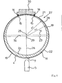
- first distance 21 from the line of action 14 at the first Film removal 12 from over the outer surface 19 of the filling tube 11 to the Line of action 14 on the second film take-off 20 (FIG. 4).
- This first stretch of 21 is from the Amount her equal to a second distance 22 which of the line of action 14 of the first Film outlet 12 goes out and over the outer surface 19 and over the Form elements 15 extends to the line of action 14 on the second film withdrawal 20.
- the Form elements 15 are provided only at the first distance 21.
- the radius of curvature R1 of the inner surface 24 of a portion 27 of the filling tube 11 sets on Crossing point 25 of the action line 14 with a perpendicular thereto, the Cross-sectional plane passing through the center line 26 at.
- the radius of curvature R2 of outer surface 28 of this region sets at the intersection 29 of Parallels 23 with the center line 26 on.
- the area 27 is provided along the first route 21. At the Embodiment of Figure 8, however, is the area 27 along the first route 21 and the second route 22 provided.
- a cross over the form of elements 15 guide member 30 is on the film tube. 4 provided, wherein the edges 16 between the mold elements 15 and the Guide element 30 extend (Figure 4).
- the radius of curvature R1 of the inner Surface 24 of region 27 is smaller than the radius of curvature R2 of the outer Surface 28 of this area 27.
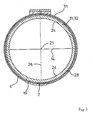
- a in a Golfrohr Sharing 31 of the forming shoulder. 2 extending portion 32 of the filling tube 11 has an outer surface 28th concentric inner surface 24 ( Figure 3).
- Figure 9) 11 are flat on the filling tube 11 flats for the better Attaching the film prints 12, 20 provided.
Landscapes
- Engineering & Computer Science (AREA)
- Mechanical Engineering (AREA)
- Containers And Plastic Fillers For Packaging (AREA)
Description
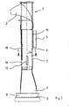
- Figur 1
- in einer Seitenansicht eine vertikale Schlauchbeutelmaschine zum Erzeugen von Schlauchbeuteln mit zwei verschweißten Bodenkanten;
- Figur 2
- in einer Seitenansicht den um 90 Grad um seine Mittelachse gedrehten Gegenstand der Figur 1;
- Figur 3
- in einem Schnitt entlang A-A der Figur 1 den Gegenstand der Figur 1, wobei sich ein Folienschlauch zwischen einem äußeren Füllrohrstück einer Formschulter und einem inneren Teilstück des Füllrohres verläuft;
- Figur 4
- in einem Schnitt entlang B-B der Figur 1 den Gegenstand der Figur 1, wobei das Füllrohr zwei unterschiedliche Radien R1 und R2 aufweist, zwei Formelemente Kanten im Folienschlauch ausbilden, und eine Längsschweiß- einrichtung eine Längsnaht verschweißt;
- Figur 5
- in einem Schnitt entlang C-C der Figur 2 zwei gegenüberliegende Folienabzüge, die an einer Wirklinie der Folienabzüge am Füllrohr ansetzen;
- Figur 6
- in einer perspektivischen Darstellung einen mittels einer Schlauchbeutelmaschine gemäß Figur 1 hergestellten Schlauchbeutel, welcher bodenseitig zwei verschweißte Kanten aufweist;
- Figur 7
- in einem Vertikalschnitt den Gegenstand der Figur 6;
- Figur 8
- in einem Horizontalschnitt ein vertikales Füllrohr analog Figur 5, jedoch mit anders angesetzten Radien R1 und R2, sowie
- Figur 9
- den um 90 Grad um seine vertikale Mittelachse gedrehten Gegenstand der Figur 8, wobei am Füllrohr Abflachungen zum besseren Angreifen der Folienabzüge vorgesehen sind.
- 1
- Schlauchbeutelmaschine
- 2
- Formschulter
- 3
- Folienbahn
- 4
- Folienschlauch
- 5
- Längsschweißeinrichtung
- 6
- Transportrichtung
- 7
- Längsnaht
- 8
- Querschweißeinrichtung
- 9
- Trenneinrichtung
- 10
- Schlauchbeutel
- 11
- Füllrohr
- 12
- Folienabzug
- 13
- Vorratsrolle
- 14
- Wirklinie
- 15
- Formelement
- 16
- Kante
- 17
- Quemaht
- 18
- Siegelelement
- 19
- äußere Oberfläche
- 20
- Folienabzug
- 21
- erste Strecke
- 22
- zweite Strecke
- 23
- Parallele zu 14
- 24
- innere Oberfläche
- 25
- Kreuzungspunkt
- 26
- Mittellinie
- 27
- Bereich
- 28
- äußere Oberfläche
- 29
- Schnittpunkt (23 mit 26)
- 30
- Führungselement
- 31
- Füllrohrstück
- 32
- Teilstück
- 33
- Abflachung
- 34
- Abstand
Claims (7)
- Vertikale Schlauchbeutelmaschine (1) mit einer Formschulter (2) zum Umformen einer Folienbahn (3) zu einem Folienschlauch (4), einer Längsschweißeinrichtung (5) zum Verschweißen des Folienschlauches (4) parallel zu seiner Transportrichtung (6) unter Erzeugung einer Längsnaht (7), einer Querschweißeinrichtung (8) zum Verschweißen des Folienschlauches (4) quer zur Transportrichtung (6) mittels Quemähten (17) einer Trenneinrichtung (9) zum Abtrennen von Schlauchbeuteln (10) vom Folienschlauch (4), einem Füllrohr (11) zum wahlweisen Befüllen der Schlauchbeutel (10), einem aus zwei am Füllrohr (11) gegenüberliegenden, das Füllrohr (11) begrenzenden, gegenläufig umlaufenden Folienabzügen (12, 20) zum Abziehen der Folienbahn (3) von einer Vorratsrolle (13) und zum Weitertransportieren des Folienschlauches (4), wobei die Folienabzüge (12, 20) entlang einer Wirklinie (14) gegen das Füllrohr (11) wirken, um den Folienschlauch (4) zwischen dem vertikalen Füllrohr (11) und den Folienabzügen (12, 20) mit Reibschluss zu ergreifen und nach unten zu bewegen, mit vom Füllrohr (11) abstehenden Formelementen (15) zur Ausbildung von ausgelenkten Kanten (16) am Folienschlauch (11), sowie mit jeweils einem Siegelelement (18) pro Formelement (15), die in Transportrichtung (6) den Formelementen (15) nachgeordnet sind, um die Kanten (16) zu verschweißen, wobei am horizontalen Querschnitt des Füllrohres (11) eine erste Strecke (21) von der Wirklinie (14) am ersten Folienabzug (12) aus über die äußere Oberfläche (19) des Füllrohres (11) bis hin zur Wirklinie (14) am zweiten Folienabzug (20), wobei ein Formelement (15) umlaufen wird, sofem es auf dieser Strecke (21) vorliegt gleich oder annähernd gleich ist wie eine zweite Strecke (22), welche von der Wirklinie (14) des ersten Folienabzugs (12) ausgeht und über die äußere Oberfläche (19) und über mindestens ein Formelement (15) hin zur Wirklinie (14) am zweiten Folienabzug (20) reicht, und die Anzahl der Formelemente (15) der beiden Strecken (21, 22) ungleich ist, dadurch gekennzeichnet, dass eine Parallele (23) in einem Abstand (34) zur Wirklinie (14) vorgesehen ist, welche ebenfalls wie die Wirklinie (14) in der Querschnittsebene liegt, dass ein Krümmungsradius (R1) der inneren Oberfläche (24) eines Bereichs (27) des Füllrohres (11) am Kreuzungspunkt (25) der Wirklinie (14) mit einer senkrecht dazu verlaufenden, die Querschnittsebene durchsetzenden Mittellinie (26) ansetzt, dass ein Krümmungsradius (R2) der äußeren Oberfläche (28) dieses Bereichs (27) am Schnittpunkt (29) der Parallelen (23) mit der Mittellinie (26) ansetzt, dass der Krümmungsradius (R1) der inneren Oberfläche (24) des Bereichs (27) kleiner als der Krümmungsradius (R2) der äußeren Oberfläche (28) dieses Bereichs (27) ist.
- Schlauchbeutelmaschine nach Anspruch 1, dadurch gekennzeichnet, dass entlang der ersten Strecke (21) kein Formelement vorliegt und entlang der zweiten Strecke (22) zwei Formelemente (15) vorgesehen sind.
- Schlauchbeutelmaschine nach Anspruch 1, dadurch gekennzeichnet, dass der Bereich (27) entlang der ersten Strecke (21) vorgesehen ist.
- Schlauchbeutelmaschine nach Anspruch 3, dadurch gekennzeichnet, dass der Bereich (27) entlang der ersten Strecke (21) und der zweiten Strecke (22) vorgesehen ist.
- Schlauchbeutelmaschine nach einem der Ansprüche 1 bis 4, dadurch gekennzeichnet, dass ein über die Formelemente (15) greifendes Führungselement (30) vorgesehen ist, wobei die Kanten (16) zwischen den Formelementen (15) und dem Führungselement (30) verlaufen.
- Schlauchbeutelmaschine nach Anspruch 1, dadurch gekennzeichnet, dass ein in einem Füllrohrstück (31) der Formschulter (2) verlaufendes Teilstück (32) des Füllrohres (11) eine zur äußeren Oberfläche (28) konzentrische innere Oberfläche (24) aufweist.
- Schlauchbeutelmaschine nach mindestens einem der Ansprüche 1 bis 6, dadurch gekennzeichnet, dass am Füllrohr (11) Abflachungen (33) zum Ansetzen der Folienabzüge (12, 20) vorgesehen sind.
Applications Claiming Priority (2)
| Application Number | Priority Date | Filing Date | Title |
|---|---|---|---|
| DE10149476A DE10149476A1 (de) | 2001-10-08 | 2001-10-08 | Schlauchbeutelmaschine zum Herstellen kantenverschweißter Schlauchbeutel |
| DE10149476 | 2001-10-08 |
Publications (2)
| Publication Number | Publication Date |
|---|---|
| EP1300338A1 EP1300338A1 (de) | 2003-04-09 |
| EP1300338B1 true EP1300338B1 (de) | 2005-10-26 |
Family
ID=7701729
Family Applications (1)
| Application Number | Title | Priority Date | Filing Date |
|---|---|---|---|
| EP02018043A Expired - Lifetime EP1300338B1 (de) | 2001-10-08 | 2002-08-13 | Vertikale Schlauchbeutelmaschine zum Herstellen kantenverschweisster Schlauchbeutel |
Country Status (4)
| Country | Link |
|---|---|
| US (2) | US20030084650A1 (de) |
| EP (1) | EP1300338B1 (de) |
| DE (2) | DE10149476A1 (de) |
| ES (1) | ES2252366T3 (de) |
Families Citing this family (4)
| Publication number | Priority date | Publication date | Assignee | Title |
|---|---|---|---|---|
| DE102004016500A1 (de) * | 2004-04-03 | 2005-10-20 | Rovema Gmbh | Vertikale Schlauchbeutelmaschine zum Verpacken horizontal ausgerichteter Gegenstandsgruppen |
| EP1813530A1 (de) * | 2006-01-31 | 2007-08-01 | Breedewegh, B.v. | Vorrichtung zum Formen einer Verpackung |
| IT201800002795A1 (it) * | 2018-02-19 | 2019-08-19 | Zanon Forming Solution S R L | Gruppo formatore verticale per buste di tipo doy-bag, o doy-pack, e simili, e busta realizzata con tale gruppo formatore |
| DE102018129676A1 (de) * | 2018-11-26 | 2020-05-28 | Hastamat Verpackungstechnik Gmbh | Vorrichtung zur Herstellung von Schlauchbeuteln mit Mehrkantsiegelung |
Family Cites Families (14)
| Publication number | Priority date | Publication date | Assignee | Title |
|---|---|---|---|---|
| US2899875A (en) * | 1959-08-18 | leasure | ||
| EP0062663A1 (de) * | 1980-10-17 | 1982-10-20 | Hayssen Manufacturing Company | Verfahren und vorrichtung zum bilden, abfüllen und absiegeln von verpackungen |
| US4442656A (en) * | 1981-10-26 | 1984-04-17 | Universal Packaging, Inc. | Filling and sealing machine for providing a flat bottom package |
| DE4431933A1 (de) * | 1994-09-08 | 1996-03-14 | Altamat Verpackungsmaschinen G | Vertikale Schlauchbeutelverpackungsmaschine |
| US5862652A (en) * | 1995-03-03 | 1999-01-26 | Rovema Packaging Machines, L.P. | Tubular bagging machine with an asymmetrical forming shoulder and tubular bags with an edge-side longitudinal seam |
| IT1280255B1 (it) | 1995-10-26 | 1998-01-05 | Ica Spa Soc | Macchina confezionatrice a tubo formatore verticale. |
| DE19539832B4 (de) * | 1995-10-26 | 2005-09-15 | Rovema Verpackungsmaschinen Gmbh | Verfahren und Vorrichtung zur Herstellung von Beuteln mit mindestens einem entlang einer Linie ausgedehnten Versteifungsbereich |
| JP3969786B2 (ja) * | 1997-05-01 | 2007-09-05 | 株式会社川島製作所 | 筒状シート成形装置 |
| IT1292642B1 (it) | 1997-06-27 | 1999-02-08 | Gino Rapparini | Processo per il confezionamento di contenitori stand-up. |
| DE19957891A1 (de) * | 1999-12-01 | 2001-06-07 | Rovema Gmbh | Schlauchbeutelmaschine |
| US7207153B1 (en) * | 1999-12-02 | 2007-04-24 | Illinois Tool Works Inc. | Method for attaching fitment at longitudinal fin seal and package resulting therefrom |
| JP4436517B2 (ja) * | 2000-01-31 | 2010-03-24 | 株式会社川島製作所 | 自立袋の製袋充填包装装置 |
| DE10017479A1 (de) * | 2000-04-07 | 2001-10-11 | Rovema Gmbh | Vertikale Schlauchbeutelmaschine und damit erzeugter Beutel |
| DE10027581B4 (de) * | 2000-06-02 | 2004-07-08 | Hastamat Verpackungstechnik Gmbh & Co. Kg | Schlauchbeutelmaschine zur Herstellung von Beuteln mit Kantensiegelung |
-
2001
- 2001-10-08 DE DE10149476A patent/DE10149476A1/de not_active Withdrawn
-
2002
- 2002-08-13 DE DE50204668T patent/DE50204668D1/de not_active Expired - Lifetime
- 2002-08-13 EP EP02018043A patent/EP1300338B1/de not_active Expired - Lifetime
- 2002-08-13 ES ES02018043T patent/ES2252366T3/es not_active Expired - Lifetime
- 2002-10-08 US US10/266,860 patent/US20030084650A1/en not_active Abandoned
-
2004
- 2004-04-21 US US10/829,055 patent/US20040194435A1/en not_active Abandoned
Also Published As
| Publication number | Publication date |
|---|---|
| EP1300338A1 (de) | 2003-04-09 |
| US20030084650A1 (en) | 2003-05-08 |
| DE10149476A1 (de) | 2003-04-17 |
| US20040194435A1 (en) | 2004-10-07 |
| ES2252366T3 (es) | 2006-05-16 |
| DE50204668D1 (de) | 2005-12-01 |
Similar Documents
| Publication | Publication Date | Title |
|---|---|---|
| EP0368095B1 (de) | Schlauchbeutelmaschine | |
| EP0627355B1 (de) | Vorrichtung zur Herstellung von Schlauchbeuteln | |
| DE2403012A1 (de) | Kunststoffbehaelter und verfahren zu seiner herstellung | |
| DE3635548C1 (de) | Waermetauscher | |
| DE19858567A1 (de) | Vorrichtung zum Herstellen von Schlauchbeutelpackungen | |
| DE102013110774A1 (de) | Vorrichtung zur Veränderung der Strahlform von fließfähigen Produkten | |
| DE202014009871U1 (de) | Verpackung mit Bodenfaltung | |
| CH621742A5 (de) | ||
| EP2480458B1 (de) | Formschulter und vorrichtung zum herstellen von schlauchbeuteln | |
| EP0797526B1 (de) | Schlauchbeutelmaschine | |
| EP1300338A1 (de) | Vertikale Schlauchbeutelmaschine zum Herstellen kantenverschweisster Schlauchbeutel | |
| DE1586029A1 (de) | Maschine zur Verpackung von Fluessigkeiten | |
| DE2213908C2 (de) | Ventilsack | |
| EP1415912A1 (de) | Formschulter zum Umformen einer Folienbahn | |
| DE19505882A1 (de) | Kombination aus zwei zusammenhängenden Beuteln und Vorrichtung zur Herstellung dieser Kombination | |
| DE10304913B4 (de) | Vorrichtung zum Aufnehmen eines Folienschlauches und vertikale Schlauchbeutelmaschine mit einer derartigen Vorrichtung | |
| DE102011004297B3 (de) | Mehrteilige Formschulter | |
| EP1415911B1 (de) | Umlenkkante zum Umformen einer Folienbahn und vertikale Schlauchbeutelmaschine mit einer derartigen Umlenkkante | |
| EP0751068A1 (de) | Vorrichtung zum Herstellen und Füllen von Beuteln | |
| DE202004007862U1 (de) | Verpackung für loses Schüttgut, insbesondere für Torf-, Erden- und Düngerprodukte o.dgl. Bodenverbesserungsmittel | |
| EP1442981A2 (de) | Vorrichtung zum Aufnehmen eines Folienschlauches und vertikale Schlauchbeutelmaschine mit einer derartigen Vorrichtung | |
| DE20205971U1 (de) | Kraftstoffbehälter mit einer Schwallwand | |
| DE2438175C3 (de) | Vorrichtung zum Formen, Füllen und Verschließen von Siegelrandbeuteln | |
| DE2639459A1 (de) | Beutel mit zwei gesiegelten laengsnaehten | |
| DE102006059003B4 (de) | Schlauchbeutelmaschine |
Legal Events
| Date | Code | Title | Description |
|---|---|---|---|
| PUAI | Public reference made under article 153(3) epc to a published international application that has entered the european phase |
Free format text: ORIGINAL CODE: 0009012 |
|
| 17P | Request for examination filed |
Effective date: 20020823 |
|
| AK | Designated contracting states |
Kind code of ref document: A1 Designated state(s): AT BE BG CH CY CZ DE DK EE ES FI FR GB GR IE IT LI LU MC NL PT SE SK TR |
|
| AX | Request for extension of the european patent |
Extension state: AL LT LV MK RO SI |
|
| 17Q | First examination report despatched |
Effective date: 20030729 |
|
| AKX | Designation fees paid |
Designated state(s): DE ES FR GB IT NL |
|
| TPAC | Observations filed by third parties |
Free format text: ORIGINAL CODE: EPIDOSNTIPA |
|
| GRAP | Despatch of communication of intention to grant a patent |
Free format text: ORIGINAL CODE: EPIDOSNIGR1 |
|
| RIN1 | Information on inventor provided before grant (corrected) |
Inventor name: BAUR, WALTER, DR. Inventor name: OHRISCH, RENE Inventor name: KANDL, FRANZ Inventor name: KUSS, GERHARD |
|
| GRAS | Grant fee paid |
Free format text: ORIGINAL CODE: EPIDOSNIGR3 |
|
| GRAA | (expected) grant |
Free format text: ORIGINAL CODE: 0009210 |
|
| AK | Designated contracting states |
Kind code of ref document: B1 Designated state(s): DE ES FR GB IT NL |
|
| REG | Reference to a national code |
Ref country code: GB Ref legal event code: FG4D Free format text: NOT ENGLISH |
|
| REF | Corresponds to: |
Ref document number: 50204668 Country of ref document: DE Date of ref document: 20051201 Kind code of ref document: P |
|
| GBT | Gb: translation of ep patent filed (gb section 77(6)(a)/1977) |
Effective date: 20060125 |
|
| REG | Reference to a national code |
Ref country code: ES Ref legal event code: FG2A Ref document number: 2252366 Country of ref document: ES Kind code of ref document: T3 |
|
| ET | Fr: translation filed | ||
| PGFP | Annual fee paid to national office [announced via postgrant information from national office to epo] |
Ref country code: FR Payment date: 20060817 Year of fee payment: 5 |
|
| PGFP | Annual fee paid to national office [announced via postgrant information from national office to epo] |
Ref country code: GB Payment date: 20060824 Year of fee payment: 5 |
|
| PGFP | Annual fee paid to national office [announced via postgrant information from national office to epo] |
Ref country code: ES Payment date: 20060830 Year of fee payment: 5 |
|
| PGFP | Annual fee paid to national office [announced via postgrant information from national office to epo] |
Ref country code: IT Payment date: 20060831 Year of fee payment: 5 |
|
| PLBE | No opposition filed within time limit |
Free format text: ORIGINAL CODE: 0009261 |
|
| STAA | Information on the status of an ep patent application or granted ep patent |
Free format text: STATUS: NO OPPOSITION FILED WITHIN TIME LIMIT |
|
| 26N | No opposition filed |
Effective date: 20060727 |
|
| PGFP | Annual fee paid to national office [announced via postgrant information from national office to epo] |
Ref country code: NL Payment date: 20070814 Year of fee payment: 6 |
|
| GBPC | Gb: european patent ceased through non-payment of renewal fee |
Effective date: 20070813 |
|
| REG | Reference to a national code |
Ref country code: FR Ref legal event code: ST Effective date: 20080430 |
|
| PG25 | Lapsed in a contracting state [announced via postgrant information from national office to epo] |
Ref country code: FR Free format text: LAPSE BECAUSE OF NON-PAYMENT OF DUE FEES Effective date: 20070831 |
|
| REG | Reference to a national code |
Ref country code: ES Ref legal event code: FD2A Effective date: 20070814 |
|
| PG25 | Lapsed in a contracting state [announced via postgrant information from national office to epo] |
Ref country code: GB Free format text: LAPSE BECAUSE OF NON-PAYMENT OF DUE FEES Effective date: 20070813 |
|
| PG25 | Lapsed in a contracting state [announced via postgrant information from national office to epo] |
Ref country code: ES Free format text: LAPSE BECAUSE OF NON-PAYMENT OF DUE FEES Effective date: 20070814 |
|
| NLV4 | Nl: lapsed or anulled due to non-payment of the annual fee |
Effective date: 20090301 |
|
| PG25 | Lapsed in a contracting state [announced via postgrant information from national office to epo] |
Ref country code: NL Free format text: LAPSE BECAUSE OF NON-PAYMENT OF DUE FEES Effective date: 20090301 |
|
| PG25 | Lapsed in a contracting state [announced via postgrant information from national office to epo] |
Ref country code: IT Free format text: LAPSE BECAUSE OF NON-PAYMENT OF DUE FEES Effective date: 20070813 |
|
| REG | Reference to a national code |
Ref country code: DE Ref legal event code: R081 Ref document number: 50204668 Country of ref document: DE Owner name: ROVEMA GMBH, DE Free format text: FORMER OWNER: ROVEMA VERPACKUNGSMASCHINEN GMBH, 35463 FERNWALD, DE Effective date: 20110915 |
|
| PGFP | Annual fee paid to national office [announced via postgrant information from national office to epo] |
Ref country code: DE Payment date: 20191022 Year of fee payment: 18 |
|
| REG | Reference to a national code |
Ref country code: DE Ref legal event code: R119 Ref document number: 50204668 Country of ref document: DE |
|
| PG25 | Lapsed in a contracting state [announced via postgrant information from national office to epo] |
Ref country code: DE Free format text: LAPSE BECAUSE OF NON-PAYMENT OF DUE FEES Effective date: 20210302 |