EP1298403A2 - Vorrichtung zum Befestigen eines Abgas-Wärmeübertragers - Google Patents
Vorrichtung zum Befestigen eines Abgas-Wärmeübertragers Download PDFInfo
- Publication number
- EP1298403A2 EP1298403A2 EP02018692A EP02018692A EP1298403A2 EP 1298403 A2 EP1298403 A2 EP 1298403A2 EP 02018692 A EP02018692 A EP 02018692A EP 02018692 A EP02018692 A EP 02018692A EP 1298403 A2 EP1298403 A2 EP 1298403A2
- Authority
- EP
- European Patent Office
- Prior art keywords
- heat exchanger
- exhaust gas
- gas heat
- holder
- fastening device
- Prior art date
- Legal status (The legal status is an assumption and is not a legal conclusion. Google has not performed a legal analysis and makes no representation as to the accuracy of the status listed.)
- Ceased
Links
Images


Classifications
-
- F—MECHANICAL ENGINEERING; LIGHTING; HEATING; WEAPONS; BLASTING
- F01—MACHINES OR ENGINES IN GENERAL; ENGINE PLANTS IN GENERAL; STEAM ENGINES
- F01N—GAS-FLOW SILENCERS OR EXHAUST APPARATUS FOR MACHINES OR ENGINES IN GENERAL; GAS-FLOW SILENCERS OR EXHAUST APPARATUS FOR INTERNAL COMBUSTION ENGINES
- F01N3/00—Exhaust or silencing apparatus having means for purifying, rendering innocuous, or otherwise treating exhaust
- F01N3/02—Exhaust or silencing apparatus having means for purifying, rendering innocuous, or otherwise treating exhaust for cooling, or for removing solid constituents of, exhaust
- F01N3/0205—Exhaust or silencing apparatus having means for purifying, rendering innocuous, or otherwise treating exhaust for cooling, or for removing solid constituents of, exhaust using heat exchangers
-
- F—MECHANICAL ENGINEERING; LIGHTING; HEATING; WEAPONS; BLASTING
- F01—MACHINES OR ENGINES IN GENERAL; ENGINE PLANTS IN GENERAL; STEAM ENGINES
- F01N—GAS-FLOW SILENCERS OR EXHAUST APPARATUS FOR MACHINES OR ENGINES IN GENERAL; GAS-FLOW SILENCERS OR EXHAUST APPARATUS FOR INTERNAL COMBUSTION ENGINES
- F01N13/00—Exhaust or silencing apparatus characterised by constructional features ; Exhaust or silencing apparatus, or parts thereof, having pertinent characteristics not provided for in, or of interest apart from, groups F01N1/00 - F01N5/00, F01N9/00, F01N11/00
- F01N13/18—Construction facilitating manufacture, assembly, or disassembly
- F01N13/1805—Fixing exhaust manifolds, exhaust pipes or pipe sections to each other, to engine or to vehicle body
-
- F—MECHANICAL ENGINEERING; LIGHTING; HEATING; WEAPONS; BLASTING
- F01—MACHINES OR ENGINES IN GENERAL; ENGINE PLANTS IN GENERAL; STEAM ENGINES
- F01N—GAS-FLOW SILENCERS OR EXHAUST APPARATUS FOR MACHINES OR ENGINES IN GENERAL; GAS-FLOW SILENCERS OR EXHAUST APPARATUS FOR INTERNAL COMBUSTION ENGINES
- F01N3/00—Exhaust or silencing apparatus having means for purifying, rendering innocuous, or otherwise treating exhaust
- F01N3/02—Exhaust or silencing apparatus having means for purifying, rendering innocuous, or otherwise treating exhaust for cooling, or for removing solid constituents of, exhaust
- F01N3/04—Exhaust or silencing apparatus having means for purifying, rendering innocuous, or otherwise treating exhaust for cooling, or for removing solid constituents of, exhaust using liquids
- F01N3/043—Exhaust or silencing apparatus having means for purifying, rendering innocuous, or otherwise treating exhaust for cooling, or for removing solid constituents of, exhaust using liquids without contact between liquid and exhaust gases
-
- F—MECHANICAL ENGINEERING; LIGHTING; HEATING; WEAPONS; BLASTING
- F28—HEAT EXCHANGE IN GENERAL
- F28F—DETAILS OF HEAT-EXCHANGE AND HEAT-TRANSFER APPARATUS, OF GENERAL APPLICATION
- F28F9/00—Casings; Header boxes; Auxiliary supports for elements; Auxiliary members within casings
- F28F9/001—Casings in the form of plate-like arrangements; Frames enclosing a heat exchange core
- F28F9/002—Casings in the form of plate-like arrangements; Frames enclosing a heat exchange core with fastening means for other structures
-
- F—MECHANICAL ENGINEERING; LIGHTING; HEATING; WEAPONS; BLASTING
- F28—HEAT EXCHANGE IN GENERAL
- F28F—DETAILS OF HEAT-EXCHANGE AND HEAT-TRANSFER APPARATUS, OF GENERAL APPLICATION
- F28F9/00—Casings; Header boxes; Auxiliary supports for elements; Auxiliary members within casings
- F28F9/007—Auxiliary supports for elements
-
- Y—GENERAL TAGGING OF NEW TECHNOLOGICAL DEVELOPMENTS; GENERAL TAGGING OF CROSS-SECTIONAL TECHNOLOGIES SPANNING OVER SEVERAL SECTIONS OF THE IPC; TECHNICAL SUBJECTS COVERED BY FORMER USPC CROSS-REFERENCE ART COLLECTIONS [XRACs] AND DIGESTS
- Y02—TECHNOLOGIES OR APPLICATIONS FOR MITIGATION OR ADAPTATION AGAINST CLIMATE CHANGE
- Y02T—CLIMATE CHANGE MITIGATION TECHNOLOGIES RELATED TO TRANSPORTATION
- Y02T10/00—Road transport of goods or passengers
- Y02T10/10—Internal combustion engine [ICE] based vehicles
- Y02T10/12—Improving ICE efficiencies
Definitions
- the present invention relates to a fastening device for fastening an exhaust gas heat exchanger to a component.
- the present invention addresses the problem of attachment an exhaust gas heat exchanger to show a way that a has increased durability.
- the invention is based on the general idea, a holder with the exhaust gas heat exchanger attached to the designated component can be designed so that this exhaust gas heat exchanger engages positively between its ends.
- a holder with the exhaust gas heat exchanger attached to the designated component can be designed so that this exhaust gas heat exchanger engages positively between its ends.
- a corresponding embodiment of the holder or of the exhaust gas heat exchanger comprehensive section of the bracket can also be achieved, that the holder at least when mounted in the longitudinal direction the exhaust gas heat exchanger relative to this adjustable or is adjustable, thereby ensuring the attachment of the exhaust gas heat exchanger Position tolerances can be compensated.
- This can also be a Simplification of the assembly can be achieved.
- the training of stresses reduced by the compensation of the positional tolerances which is advantageous for the durability of the proposed fastening device effect.
- the holder can consist of two holding parts, each having a peripheral portion of the Exhaust heat exchanger encompassing receiving portion and at least having a retaining tab, wherein the exception portions of the two Holding parts with assembled bracket the exhaust heat exchanger closed, wherein the retaining tabs of the two holding parts at assembled holder to each other, so that they together can be fastened to the component. Due to this construction, the fastening process, with the exhaust gas heat exchanger on each component should be fastened, greatly simplified, since the holder in front Location, so can be completed directly on the exhaust heat exchanger.
- each holding part can be a connecting lug have, which connected together with assembled bracket are.
- the connecting straps For example, be shaped so that when assembling the bracket two formed on the connecting tabs complementary parts interlock positively. Likewise it is possible the two holding parts in the area of their connecting straps to screw together riveted, welded or soldered.
- At least one of the holding parts in the receiving section to the exhaust gas heat exchanger projecting ribs and / or nubs.
- These ribs or nubs come in appropriately sized bracket on the exhaust heat exchanger for Plant and can punctiform or linear holding forces on the exhaust gas heat exchanger Apply, thereby ensuring a safe and reliable Positioning of the exhaust gas heat exchanger relative to the respective component is supported.
- the assembly of the fastening device according to the invention can thereby be relieved that the retaining tabs on one side of the holder as a U-shaped Forks are formed, which are all open in the same direction. This makes it possible, the laterally open retaining tabs on the same time to attach already pre-assembled screws. Likewise, the so allow formed retaining tabs compensate for positional tolerances.
- a fastening device 1 a holder 2, which is an exhaust heat exchanger. 3 completely engages between its ends 4 and 5.
- the holder 2 has on one side of the exhaust gas heat exchanger 3, two retaining tabs 6 and 7 on, with which the holder 2 on a suitable component, not shown can be attached.
- the holder 2 is about their retaining tabs 6 and 7 bolted to a vehicle body.
- the retaining tabs 6 and 7 are here equipped with U-shaped forks 8, wherein the Forks 8 of the two retaining tabs 6 and 7 are open in the same direction. In this way, the holder 2 on pre-assembled or inserted Screws are slotted sideways, eliminating the assembly process considerably more rationally feasible.
- the holder 2 is made two holding parts, namely a first holding part 9 and a second Holding part 10, constructed. These two holding parts 9 and 10 are quasi shaped complementary to each other, so that both each have a peripheral portion embrace the exhaust gas heat exchanger 3, such that the two Holding parts 9, 10 with assembled bracket 2 the exhaust heat exchanger 3 closed, cf. in particular Fig. 3.
- the Holding parts 9 and 10 are for this purpose in each case with a receiving portion 11 and 12 equipped, the inner contour in each case to the outer contour the associated peripheral portion of the exhaust gas heat exchanger 3 is adjusted.
- Each holding part 9, 10 here has two retaining tabs 6, 7, which are shaped and arranged so that they are assembled at Holder 2 are substantially congruent to each other, so that the superimposed retaining tabs 6 and 7 together, so as a single Retaining tab 6, 7, can be fastened to the respective component.
- This Construction simplifies assembly.
- both holding parts 9, 10 each with a connecting strap 13 be equipped, in which the holding parts 9, 10 at assembled Holder 2 are connected to each other.
- both connecting straps are provided with a passage opening 14, inserted through a connecting screw and bolted to a nut can be.
- the bracket 2 with the respective component connect to.
- bracket 2 To adapt the bracket 2 to the particular installation situation, it can For example, be required, the connecting tabs 13 against the Retaining tabs 6, 7 angled, which for example from the sectional views evident.
- the holder 2 is so designed that they the exhaust heat exchanger 3 in the assembled Condition with a self-retaining clamp seat surrounds.
- the relative position between Holder 2 and exhaust heat exchanger 3 is then fixed.
- nubs 15 formed, which protrude in the direction of exhaust heat exchanger 3 from the holding part 9, 10.
- These nubs 15 are in Figs. 4 and 6 and 7 and 9 particularly clearly.
- These nubs 15 form at a corresponding dimensioning the receiving portions 11, 12 and when assembled Bracket 2 point-shaped force application points that provide an effective clamping action and thus an effective fixation of the holder 2 on the exhaust gas heat exchanger 3 guarantee.
- the nubs 15 can, for example be prepared in that at corresponding points on the of Exhaust heat exchanger 3 opposite outer side of the respective holding part 9, 10 corresponding recesses 16 introduced, in particular, hit, become. Additionally or alternatively to such nubs 15 may also protruding ribs may be provided to improve the clamping action or produce.
- the holding parts 9 and 10 can be particularly inexpensive and simply by forming, Bending, punching made of sheet metal parts. Accordingly the fastening device 1 according to the invention is particularly inexpensive to produce.
- the exhaust gas heat exchanger. 3 encloses positively, this is at least captive on the respective Component attached. If also between bracket 2 and exhaust heat exchanger 3 a self-retaining press fit is realized, can also with high reliability, a predetermined relative position between exhaust heat exchanger 3 and the respective component can be ensured. From Of particular importance here is that the fastening device according to the invention 1 without a welded joint or solder joint between the holder 2 and the exhaust heat exchanger 3 manages. material weaknesses at the exhaust heat exchanger 3, which is characterized by such Welding or solder joints can be formed, thereby avoiding so that the life of the exhaust gas heat exchanger 3 and the connection of the exhaust gas heat exchanger 3 is increased to the respective component.
Abstract
Description
- Fig. 1
- eine Draufsicht auf einen Abgas-Wärmeübertrager mit daran angebrachter erfindungsgemäßer Befestigungsvorrichtung,
- Fig. 2
- eine Seitenansicht entsprechend einem Pfeil II in Fig. 1 auf den mit der erfindungsgemäßen Befestigungsvorrichtung ausgestatteten Abgas-Wärmeübertrager,
- Fig. 3
- einen Querschnitt durch die erfindungsgemäße Befestigungsvorrichtung entsprechend den Schnittlinien III in Fig. 1,
- Fig. 4
- eine Draufsicht auf ein erstes Halteteil der erfindungsgemäßen Befestigungsvorrichtung,
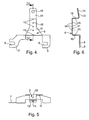
- Fig. 5
- eine Seitenansicht auf das erste Halteteil,
- Fig. 6
- eine Schnittansicht des ersten Halteteils entsprechend den Schnittlinien VI in Fig. 4,
- Fig. 7
- eine Draufsicht auf ein zweites Halteteil der erfindungsgemäßen Befestigungsvorrichtung,
- Fig. 8
- eine Seitenansicht auf das zweite Halteteil und
- Fig. 9
- eine Schnittansicht des zweiten Halteteils entsprechend den Schnittlinien IX in Fig. 7.
- 1
- Befestigungsvorrichtung
- 2
- Halterung
- 3
- Abgas-Wärmeübertrager
- 4
- Ende von 3
- 5
- Ende von 3
- 6
- Haltelasche
- 7
- Haltelasche
- 8
- Gabel
- 9
- erstes Halteteil
- 10
- zweites Halteteil
- 11
- Aufnahmeabschnitt von 9
- 12
- Aufnahmeabschnitt von 10
- 13
- Verbindungslasche
- 14
- Durchgangsöffnung in 13
- 15
- Noppe
- 16
- Vertiefung
Claims (6)
- Befestigungsvorrichtung zum Befestigen eines Abgas-Wärmeübertragers (3) an einem Bauteil, mit einer den Abgas-Wärmeübertrager (3) zwischen seinen Enden (4, 5) geschlossen umfassenden Halterung (2), die wenigstens eine Haltelasche (6, 7, 13) aufweist, mit der die Halterung (2) am Bauteil befestigbar ist.
- Befestigungsvorrichtung nach Anspruch 1,
dadurch gekennzeichnet, daß die Halterung (2) so ausgebildet ist, daß sie den Abgas-Wärmeübertrager (3) mit einem selbsthaltenden Klemmsitz umgreift. - Befestigungsvorrichtung nach Anspruch 1 oder 2,
dadurch gekennzeichnet, daß die Halterung (2) aus zwei Halteteilen (9, 10) besteht, die jeweils einen einen Umfangsabschnitt des Abgas-Wärmeübertragers (3) umgreifenden Aufnahmeabschnitt (11, 12) und wenigstens eine Haltelasche (6, 7, 13) aufweisen, wobei die Aufnahmeabschnitte (11, 12) der beiden Halteteile (9, 10) bei zusammengebauter Halterung (2) den Abgas-Wärmeübertrager (3) geschlossen umfassen und wobei die Haltelaschen (6, 7, 13) der beiden Halteteile (9, 10) bei zusammengebauter Halterung (2) aufeinander liegen, derart, daß sie gemeinsam am Bauteil befestigbar sind. - Befestigungsvorrichtung nach Anspruch 3,
dadurch gekennzeichnet, daß jedes Halteteil (9,10) eine Verbindungslasche (13) aufweist, die bei zusammengebauter Halterung (2) miteinander verbunden sind. - Befestigungsvorrichtung nach Anspruch 3 oder 4,
dadurch gekennzeichnet, daß wenigstens eines der Halteteile (9, 10) im Aufnahmeabschnitt (11, 12) zum Abgas-Wärmeübertrager (3) vorstehende Rippen und/oder Noppen (15) aufweist. - Befestigungsvorrichtung nach einem der Ansprüche 1 bis 5,
dadurch gekennzeichnet, daß an einer Seite der Halterung (2) die Haltelaschen (6, 7) mit U-förmigen Gabeln ausgestattet sind, die in derselben Richtung offen sind.
Applications Claiming Priority (2)
| Application Number | Priority Date | Filing Date | Title |
|---|---|---|---|
| DE10147555.1A DE10147555B4 (de) | 2001-09-26 | 2001-09-26 | Vorrichtung zum Befestigen eines Abgas-Wärmeübertragers |
| DE10147555 | 2001-09-26 |
Publications (2)
| Publication Number | Publication Date |
|---|---|
| EP1298403A2 true EP1298403A2 (de) | 2003-04-02 |
| EP1298403A3 EP1298403A3 (de) | 2006-05-10 |
Family
ID=7700421
Family Applications (1)
| Application Number | Title | Priority Date | Filing Date |
|---|---|---|---|
| EP02018692A Ceased EP1298403A3 (de) | 2001-09-26 | 2002-08-21 | Vorrichtung zum Befestigen eines Abgas-Wärmeübertragers |
Country Status (3)
| Country | Link |
|---|---|
| US (1) | US6640881B2 (de) |
| EP (1) | EP1298403A3 (de) |
| DE (1) | DE10147555B4 (de) |
Cited By (3)
| Publication number | Priority date | Publication date | Assignee | Title |
|---|---|---|---|---|
| EP1884634A3 (de) * | 2006-08-04 | 2008-12-31 | Toyota Jidosha Kabushiki Kaisha | Stützstruktur für den Wärmetauscher eines Abgassystems |
| EP1953023A3 (de) * | 2007-02-05 | 2009-09-02 | Toyota Jidosha Kabushiki Kaisha | Montage eines Abgasanlagewärmetauschers an der Fahrzeugkarosserie |
| EP2587207A1 (de) * | 2011-10-28 | 2013-05-01 | Deere & Company | Energiesystem |
Families Citing this family (5)
| Publication number | Priority date | Publication date | Assignee | Title |
|---|---|---|---|---|
| DE102009031980C5 (de) | 2009-07-06 | 2017-12-14 | Benteler Automobiltechnik Gmbh | Verfahren und Vorrichtung zur Befestigung eines Abgaskonvertermoduls |
| DE102010014816B4 (de) | 2010-04-13 | 2024-02-29 | Friedrich Boysen Gmbh & Co. Kg | Vorrichtung zur Halterung einer Abgasanlagenkomponente |
| DE102010037152B4 (de) * | 2010-08-25 | 2022-08-25 | Gea Wtt Gmbh | Plattenwärmetauscher in abgedichteter Ausführung |
| DE102015010513B3 (de) * | 2015-08-13 | 2016-11-17 | Audi Ag | Befestigungsanordnung |
| FR3065488B1 (fr) * | 2017-04-20 | 2019-06-28 | Faurecia Systemes D'echappement | Element de ligne d'echappement et procede de fabrication d'un tel element |
Citations (3)
| Publication number | Priority date | Publication date | Assignee | Title |
|---|---|---|---|---|
| US2081546A (en) * | 1934-03-29 | 1937-05-25 | Hupp Motor Car Corp | Muffler mounting |
| US3014681A (en) * | 1955-08-19 | 1961-12-26 | Int Harvester Co | Motor vehicle exhaust muffler support means |
| DE19836889A1 (de) | 1998-08-14 | 2000-02-17 | Modine Mfg Co | Abgaswärmetauscher |
Family Cites Families (21)
| Publication number | Priority date | Publication date | Assignee | Title |
|---|---|---|---|---|
| US1882555A (en) * | 1929-02-27 | 1932-10-11 | Emmet P Gray | Muffler supporting device |
| US2415154A (en) * | 1943-11-26 | 1947-02-04 | Walter Gustave | Outboard engine cooling device |
| DE1729526U (de) * | 1955-02-18 | 1956-09-06 | Opel Adam Ag | Anordnung und aufhaengung der auspuffleitung von kraftfahrzeugen. |
| US2912198A (en) * | 1955-08-19 | 1959-11-10 | Int Harvester Co | Motor vehicle exhaust muffler support means |
| DE1729526B2 (de) * | 1968-01-18 | 1975-04-10 | Chemische Werke Huels Ag, 4370 Marl | Einrichtung zur Herstellung von blähfähigen thermoplastischen Kunststotfgranulaten |
| US4230176A (en) * | 1978-04-24 | 1980-10-28 | Caterpillar Tractor Co. | Floating radiator tank top |
| JPS5571920U (de) * | 1978-11-14 | 1980-05-17 | ||
| US4436145A (en) * | 1981-11-06 | 1984-03-13 | The Garrett Corporation | Charge air cooler mounting arrangement |
| JPS63180092A (ja) * | 1987-01-21 | 1988-07-25 | Matsushita Refrig Co | 二重管式熱交換器の取付装置 |
| GB2212771A (en) * | 1987-11-24 | 1989-08-02 | Vauxhall Motors Ltd | Adjustable exhaust system |
| JPH01181094A (ja) * | 1988-01-11 | 1989-07-19 | Hitachi Ltd | 横型熱交換器の支持装置 |
| JPH0645155Y2 (ja) * | 1988-10-24 | 1994-11-16 | サンデン株式会社 | 熱交換器 |
| JP3051478B2 (ja) * | 1991-03-15 | 2000-06-12 | 昭和アルミニウム株式会社 | 熱交換器における取付け用ブラケットのろう付け方法 |
| US5407161A (en) * | 1993-03-25 | 1995-04-18 | Valeo Engine Cooling, Inc. | Bracket to be secured to a cylindrical object |
| JPH07190668A (ja) * | 1993-12-28 | 1995-07-28 | Showa Alum Corp | 熱交換器 |
| DE19621271A1 (de) * | 1995-06-21 | 1997-01-09 | Witzenmann Metallschlauchfab | Flexibles Leitungselement für Abgasleitungen von Kraftfahrzeugen |
| DE19815705A1 (de) * | 1998-04-08 | 1999-10-14 | Daimler Chrysler Ag | Befestigungsvorrichtung zum Befestigen eines Abgasrohres an einem Fahrzeugbauteil |
| GB9823669D0 (en) * | 1998-10-30 | 1998-12-23 | Serck Heat Transfer Limited | Exhaust gas cooler |
| US6123143A (en) * | 1998-11-17 | 2000-09-26 | Norsk Hydro | Heat exchanger combination mounting bracket and inlet/outlet block with locking sleeve |
| JP3633824B2 (ja) * | 1999-03-30 | 2005-03-30 | 日産ディーゼル工業株式会社 | Egrクーラの支持装置 |
| US6332495B1 (en) * | 1999-06-02 | 2001-12-25 | Long Manufacturing Ltd. | Clip on manifold heat exchanger |
-
2001
- 2001-09-26 DE DE10147555.1A patent/DE10147555B4/de not_active Expired - Lifetime
-
2002
- 2002-08-21 EP EP02018692A patent/EP1298403A3/de not_active Ceased
- 2002-09-23 US US10/252,627 patent/US6640881B2/en not_active Expired - Fee Related
Patent Citations (3)
| Publication number | Priority date | Publication date | Assignee | Title |
|---|---|---|---|---|
| US2081546A (en) * | 1934-03-29 | 1937-05-25 | Hupp Motor Car Corp | Muffler mounting |
| US3014681A (en) * | 1955-08-19 | 1961-12-26 | Int Harvester Co | Motor vehicle exhaust muffler support means |
| DE19836889A1 (de) | 1998-08-14 | 2000-02-17 | Modine Mfg Co | Abgaswärmetauscher |
Cited By (6)
| Publication number | Priority date | Publication date | Assignee | Title |
|---|---|---|---|---|
| EP1884634A3 (de) * | 2006-08-04 | 2008-12-31 | Toyota Jidosha Kabushiki Kaisha | Stützstruktur für den Wärmetauscher eines Abgassystems |
| EP1953023A3 (de) * | 2007-02-05 | 2009-09-02 | Toyota Jidosha Kabushiki Kaisha | Montage eines Abgasanlagewärmetauschers an der Fahrzeugkarosserie |
| CN101239581B (zh) * | 2007-02-05 | 2010-12-01 | 丰田自动车株式会社 | 包括排气系统热交换器的车身安装结构 |
| US8074762B2 (en) | 2007-02-05 | 2011-12-13 | Toyota Jidosha Kabushiki Kaisha | Vehicle body mounting configuration including exhaust system heat exchanger |
| EP2587207A1 (de) * | 2011-10-28 | 2013-05-01 | Deere & Company | Energiesystem |
| US8770177B2 (en) | 2011-10-28 | 2014-07-08 | Deere & Company | Corrugated strap for securing a heat exchanger |
Also Published As
| Publication number | Publication date |
|---|---|
| DE10147555A1 (de) | 2003-04-10 |
| EP1298403A3 (de) | 2006-05-10 |
| DE10147555B4 (de) | 2014-01-30 |
| US6640881B2 (en) | 2003-11-04 |
| US20030056937A1 (en) | 2003-03-27 |
Similar Documents
| Publication | Publication Date | Title |
|---|---|---|
| EP0659615B1 (de) | Pedalwerk für ein Fahrzeug | |
| DE20220866U1 (de) | Spindel- oder Schneckenantrieb für Verstelleinrichtungen in Kraftfahrzeugen | |
| DE10036575A1 (de) | Vorrichtung zur elastiscchen Lagerung eines hydraulischen Aggregats einer Fahrzeugbremsanlage in einem Fahrzeug | |
| DE10340665A1 (de) | Kraftspeicher für eine Reibungskupplung | |
| WO2008019788A1 (de) | Kraftfahrzeug mit zumindest einem längsträger | |
| DE10250994A1 (de) | Spindel- oder Schneckenantrieb für Verstelleinrichtungen in Kraftfahrzeugen | |
| EP0175856A2 (de) | Spannmuffe mit einer Spannschraube | |
| EP1772633B1 (de) | Vorrichtung zum Verschrauben zweier Bauteile mit Toleranzausgleich | |
| DE19925701A1 (de) | Elastisches Wellengelenk | |
| EP2730456A1 (de) | Antrieb einer Sitzverstelleinrichtung für Kraftfahrzeuge | |
| DE3841666A1 (de) | Befestigungsvorrichtung zum befestigen rohrfoermiger bauteile, durch die ein fluid hindurchstroemt | |
| EP1298403A2 (de) | Vorrichtung zum Befestigen eines Abgas-Wärmeübertragers | |
| DE202007018727U1 (de) | Abschleppbuchseneinheit | |
| EP3128145B1 (de) | Justierbare halterung für eine abgasanlage und verfahren zur befestigung einer halterung für eine abgasanlage | |
| DE2545809A1 (de) | Vorrichtung zur anbringung eines servolenkgetriebes an einer fahrzeugachse | |
| EP0573764A1 (de) | Gelenkige Verbindung von Rohrteilen, insbesondere bei Abgasleitungen von Kraftfahrzeugen | |
| EP1712419B1 (de) | Dachrelinganordnung und Verfahren zur Herstellung einer Dachrelinganordnung | |
| EP3419837B1 (de) | Achssystem | |
| DE19714700C2 (de) | Abgasanlangenanordnung eines Kraftfahrzeugs | |
| DE102016107048B4 (de) | Rahmeneinheit | |
| DE3243238A1 (de) | Gabelkopf | |
| DE3637162A1 (de) | Vorderwagen eines kraftfahrzeuges, insbesondere eines personenkraftwagens | |
| DE102015012591A1 (de) | Rohrverbindungsanordnung und Rohrverbindung zweier Rohre | |
| EP2307245A1 (de) | Platine mit formrohr zur führung und lagerung einer antriebswelle | |
| EP3802169B1 (de) | Achsmontageeinheit |
Legal Events
| Date | Code | Title | Description |
|---|---|---|---|
| PUAI | Public reference made under article 153(3) epc to a published international application that has entered the european phase |
Free format text: ORIGINAL CODE: 0009012 |
|
| AK | Designated contracting states |
Kind code of ref document: A2 Designated state(s): AT BE BG CH CY CZ DE DK EE ES FI FR GB GR IE IT LI LU MC NL PT SE SK TR Designated state(s): AT BE BG CH CY CZ DE DK EE ES FI FR GB GR IE IT LI LU MC NL PT SE SK TR |
|
| AX | Request for extension of the european patent |
Extension state: AL LT LV MK RO SI |
|
| RAP1 | Party data changed (applicant data changed or rights of an application transferred) |
Owner name: BEHR GMBH & CO. KG |
|
| PUAL | Search report despatched |
Free format text: ORIGINAL CODE: 0009013 |
|
| AK | Designated contracting states |
Kind code of ref document: A3 Designated state(s): AT BE BG CH CY CZ DE DK EE ES FI FR GB GR IE IT LI LU MC NL PT SE SK TR |
|
| AX | Request for extension of the european patent |
Extension state: AL LT LV MK RO SI |
|
| 17P | Request for examination filed |
Effective date: 20061031 |
|
| AKX | Designation fees paid |
Designated state(s): AT BE BG CH CY CZ DE DK EE ES FI FR GB GR IE IT LI LU MC NL PT SE SK TR |
|
| 17Q | First examination report despatched |
Effective date: 20071011 |
|
| STAA | Information on the status of an ep patent application or granted ep patent |
Free format text: STATUS: THE APPLICATION HAS BEEN REFUSED |
|
| 18R | Application refused |
Effective date: 20131121 |