EP1298033A1 - Tragrahmen für ein Fahrgestell eines Nutzfahrzeuges - Google Patents
Tragrahmen für ein Fahrgestell eines Nutzfahrzeuges Download PDFInfo
- Publication number
- EP1298033A1 EP1298033A1 EP02016545A EP02016545A EP1298033A1 EP 1298033 A1 EP1298033 A1 EP 1298033A1 EP 02016545 A EP02016545 A EP 02016545A EP 02016545 A EP02016545 A EP 02016545A EP 1298033 A1 EP1298033 A1 EP 1298033A1
- Authority
- EP
- European Patent Office
- Prior art keywords
- platform
- piece
- support frame
- supporting frame
- internal combustion
- Prior art date
- Legal status (The legal status is an assumption and is not a legal conclusion. Google has not performed a legal analysis and makes no representation as to the accuracy of the status listed.)
- Granted
Links
- 238000002485 combustion reaction Methods 0.000 claims description 42
- 230000005540 biological transmission Effects 0.000 claims description 9
- 238000010276 construction Methods 0.000 description 7
- 238000009434 installation Methods 0.000 description 5
- 238000012423 maintenance Methods 0.000 description 5
- 230000005484 gravity Effects 0.000 description 2
- 230000010354 integration Effects 0.000 description 2
- 238000005452 bending Methods 0.000 description 1
- 239000002826 coolant Substances 0.000 description 1
- 238000013016 damping Methods 0.000 description 1
- 238000005538 encapsulation Methods 0.000 description 1
- 239000002828 fuel tank Substances 0.000 description 1
- 238000004519 manufacturing process Methods 0.000 description 1
- 239000000463 material Substances 0.000 description 1
- 239000000725 suspension Substances 0.000 description 1
Images

Classifications
-
- B—PERFORMING OPERATIONS; TRANSPORTING
- B60—VEHICLES IN GENERAL
- B60K—ARRANGEMENT OR MOUNTING OF PROPULSION UNITS OR OF TRANSMISSIONS IN VEHICLES; ARRANGEMENT OR MOUNTING OF PLURAL DIVERSE PRIME-MOVERS IN VEHICLES; AUXILIARY DRIVES FOR VEHICLES; INSTRUMENTATION OR DASHBOARDS FOR VEHICLES; ARRANGEMENTS IN CONNECTION WITH COOLING, AIR INTAKE, GAS EXHAUST OR FUEL SUPPLY OF PROPULSION UNITS IN VEHICLES
- B60K5/00—Arrangement or mounting of internal-combustion or jet-propulsion units
- B60K5/12—Arrangement of engine supports
-
- B—PERFORMING OPERATIONS; TRANSPORTING
- B62—LAND VEHICLES FOR TRAVELLING OTHERWISE THAN ON RAILS
- B62D—MOTOR VEHICLES; TRAILERS
- B62D21/00—Understructures, i.e. chassis frame on which a vehicle body may be mounted
- B62D21/11—Understructures, i.e. chassis frame on which a vehicle body may be mounted with resilient means for suspension, e.g. of wheels or engine; sub-frames for mounting engine or suspensions
-
- B—PERFORMING OPERATIONS; TRANSPORTING
- B62—LAND VEHICLES FOR TRAVELLING OTHERWISE THAN ON RAILS
- B62D—MOTOR VEHICLES; TRAILERS
- B62D21/00—Understructures, i.e. chassis frame on which a vehicle body may be mounted
- B62D21/12—Understructures, i.e. chassis frame on which a vehicle body may be mounted assembled from readily detachable parts
Definitions
- the invention relates to a support frame for a chassis a commercial vehicle, in particular a truck, with the features of the preamble of claim 1.
- Such a support frame is for example from the DE 197 50 981 A1 is known and has two parallel to the vehicle longitudinal direction, in the vehicle transverse direction spaced apart longitudinal members, which are interconnected via cross members. Each side member is assembled from a top material, a bottom flange and a plurality of vertical webs, these webs each upper chord and lower chord connect.
- the support frame built in this way can be adapted to a very small amount of effort by selecting and combining straps, webs and cross beams which differ in stiffness values from one another to very different forms of application which differ, for example, in terms of stiffness, in particular torsional rigidity become.
- From DE 198 60 238 A1 is another support frame for a Chassis of a commercial vehicle known to be two parallel to the Vehicle longitudinal direction extending, in the vehicle transverse direction spaced apart and interconnected by cross members Longitudinal beams has.
- An internal combustion engine of Commercial vehicle is on top of the support frame on the Side members put on, it being in the internal combustion engine is a standing in-line engine.
- the cab only after the assembly of the internal combustion engine on the Support frame are placed. Because of this arrangement can a cab floor is usually not flat, because the upwardly projecting contour of the internal combustion engine must be taken into account.
- a mounted in this way Internal combustion engine is relatively difficult to access for maintenance purposes, so that elaborate arrangements are made in order to ensure adequate maintenance. For example, it is known to design the cab in such a way that it can be tilted completely forward.
- DE 197 33 470 C1 shows a side member for a support frame a commercial vehicle that extends longitudinally having the longitudinal beam extending central web, the its top and at the bottom of each one flanked angled profile legs.
- the side member is provided with at least one bend.
- the central pier and the two profile legs are manufactured as separate and designed rigidly interconnected components, wherein the plate-shaped center bar at the level of the bend accordingly is bent.
- the present invention deals with the problem for a support frame of the type mentioned an embodiment which facilitates the assembly of the commercial vehicle.
- the invention is based on the general idea for which Assembly of the internal combustion engine one, in particular self-supporting, Provide platform pre-assembled from below into the platform Support frame is used.
- This platform is made with centerpieces the lower chords are formed, so that the integration the platform in the supporting frame completes the lower straps, while the upper straps are independent of this platform are completed.
- the upper straps also give the support frame if not yet used platform or dismantled Platform sufficient strength for the support frame, the especially sufficient to other vehicle components, such as e.g. Axles, side attachments and superstructures, on the supporting frame too assemble.
- the internal combustion engine be mounted on the top of the platform, so in that the internal combustion engine is inserted in the support frame and attached platform vertically between the upper straps and the lower chords is arranged.
- the internal combustion engine and possibly further Components of the drive train in the interior of the support frame integrated which on the one hand for the driving dynamics advantageous low center of gravity of the vehicle is achievable and which On the other hand, simplifies the assembly of vehicle bodies.
- the internal combustion engine and optionally other components the powertrain so in the support frame to place this do not project upwards over the upper straps of the support frame. This construction offers an additional simplification of the assembly of vehicle bodies, as little or no interference contours must be taken into account.
- this makes it possible to form a cab with a flat bottom, which its manufacturability is simplified and its stability elevated. Tipping the cab for maintenance the internal combustion engine is no longer necessary, as these Design allows lateral maintenance of the internal combustion engine.
- the internal combustion engine is no longer on the support frame the position under the cab is restricted so that e.g. Same drive trains with different lengths of chassis are usable.
- the Internal combustion engine attached to the platform via engine mounts is, which are formed on the auxiliary crossbeams.
- the internal combustion engine indirectly to the lower flange middle pieces supported, on the one hand, the effective Forces are transferred to the centerpieces over a larger area.
- the support of the internal combustion engine is characterized exactly where the platform by the connection of the Auxiliary cross member has its highest strength.
- a support frame 1 a chassis of a commercial vehicle, not shown otherwise, in particular a lorry, two parallel to a vehicle longitudinal direction symbolized by an arrow 2 extending side members 3, of which in Fig. 1, however only the side rail 3 facing the viewer can be seen is.
- the other side member 3 is congruent behind the visible side member 3.
- the two side members. 3 are spaced from each other in the vehicle transverse direction and appropriately interconnected via a plurality of cross member 4.
- the longitudinal members 3 are as so-called "built-longitudinal members” formed and have a top flange 5 and a bottom flange. 6 on, connected to each other via a plurality of vertical webs 7 are.
- the straps 5 and 6 and the webs 7 provided with a hole pattern, which is a simple Screwing of the individual parts for assembling the side members 3 allows. In this hole pattern are also the cross member. 4 integrated, so that the assembly of the support frame 1 Overall, relatively easy to carry out.
- the lower straps 6 are each longitudinal beam 3 formed at least three parts, so that each lower flange. 6 with respect to the direction of travel, a frontal front piece 8, a rear tail piece 9 and a between front piece 8 and tail piece 9 lying centerpiece 10 has.
- These lower chord pieces 8, 9, 10 are dimensioned so that they are overlap each other at their ends and over the hole pattern can be attached to each other.
- the middle pieces 10 both Bottom straps 6 are connected to each other via at least two auxiliary cross members 11 connected, creating a self-supporting platform 12th is formed, which is preassembled as such and in the otherwise also preassembled support frame 1 to its completion can be used and attached to it.
- a gear 14 is arranged on the platform 12.
- the transmission 14 may also be a retarder on the Be arranged platform 12; it is also possible, instead of the transmission 14 to mount a transmission-retarder unit.
- a drive shaft 15 extends from the transmission 14 to a driven rear axle 16, which are mounted on the support frame 3 is.
- Trailing arm 17 of a rear suspension can be for example, on one of the webs 7 support.
- a rear wheel 18 is symbolized by a circle.
- the support frame 3 without the platform 12 are relatively largely completed. In particular can the support frame 3 without the platform 12 too a chassis and ultimately to a commercial vehicle be completed. Regardless of this incomplete Support frame 3, the platform 12 pre-assembled and with the Internal combustion engine 13 and here equipped with the transmission 14 become. Here are the components mentioned, ie the engine 13 and the transmission 14, on an upper side the platform 12 mounted.
- the pre-assembled Platform 12 are characterized the internal combustion engine 13 and the Transmission 14 within the support frame 3, in particular between the upper belt 5 and the lower belt 6, arranged. This results an extremely low construction for the support frame 1.
- the positioning of the internal combustion engine 13 between upper flange 5 and lower flange 6 allows easy maintenance of to make the page.
- the integration of the internal combustion engine 13 in the interior of the support frame 1 also simplifies a sound-insulating encapsulation of the internal combustion engine 13. Above In addition, this can lead to interference contours that go up over the top flange 5 protrude, be avoided, causing the Installation of vehicle bodies simplified.
- This embodiment is also characterized in that the position the internal combustion engine 13 with respect to the longitudinal direction 2 am Support frame 1 is now independent of the position of one the support frame 1 attached cab. Especially at Tractor units can thus be the center of gravity of the semi-trailer be moved advantageously to the rear.
- connection of the platform 12 to the support frame 1 is at least by attachment of the centerpieces 10 to the Front pieces 8 and at the tail pieces 9.
- the other is at the embodiment shown here at one of the centerpiece 10th facing the end 19 of the front piece 8 one of the vertical Webs 7 arranged over the center piece 10 at a corresponding end 20 connected to the associated upper flange 5 is.
- a vertical Ridge 7 attached, via which a corresponding end 22 of the Middle piece 10 is attached to the upper flange 5.
- another vertical web 7 may be provided, which is the middle piece 10 connects to the upper belt 5.
- Another stiffening can be achieved that on the front part 8 in the field of overlapping ends 19 and 20 of the cross member. 4 is arranged.
- Cross member 4 is also one of Cross member 4 at the overlapping ends 21 and 22 am Rear piece 9 attached.
- the Platform 12 For the attachment of the platform 12 on the support frame 1 are releasable fasteners, such as e.g. Screws, preferably, around thereby a simplified expansion of the platform 12 from the To enable support frame 1. Due to this design, the Platform 12 together with the components mounted on it (e.g., engine 13 and transmission 14) are modularly dismantled, be serviced and replaced if necessary.
- releasable fasteners such as e.g. Screws
- the platform 12 can also be shorter than at be formed of the embodiment of FIG. 1. expedient the attachment of the internal combustion engine 13 via engine mount 23, to realize a vibration damping.
- these motor bearings 23 are formed on the auxiliary cross members 11, so that the internal combustion engine 13 on the Auxiliary cross member 11 is supported on the middle pieces 10.
- these motor bearings 23 are preferably on the Ends of the auxiliary cross member 11 are arranged, where the auxiliary cross member 11 rest on the middle pieces 10. At this Construction, the attachment of the internal combustion engine 13 is accurate in the places of the platform 12, which has the highest strength feature.
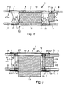
- Fig. 3 is also the special installation of an internal combustion engine 13 reproduced, which is designed as a horizontal motor lying is.
- the internal combustion engine 13 may have the situation shown in FIG occur, after which the internal combustion engine 13 at least one side of the support frame 1 projects laterally beyond this.
- the internal combustion engine 13 is then usually still inside the chassis, which is the central support frame 1 regularly relatively far laterally enlarged. instead a lying in-line engine can also be a boxer engine for use come.
- the internal combustion engine 13 may also be on both sides of the support frame 1 protrude beyond its side member 3.
- the construction shown of the support frame 1 allows by his built longitudinal member 3 a structure with sections relative large vertical height (see Fig. 1), causing local relatively high resistance moments and thus relatively low bending stresses let represent. Likewise, this results a very high rigidity for the support frame 1.
- the side members 3 have due to their Construction a relatively low weight.
- the vertical webs 7 can additionally spring brace, Trailing arm and console functions have.
- the complete powertrain can also be considered in terms of Length can be standardized, so the distance between Internal combustion engine 13 and driven axle at different Vehicle lengths can remain the same.
Landscapes
- Engineering & Computer Science (AREA)
- Chemical & Material Sciences (AREA)
- Combustion & Propulsion (AREA)
- Transportation (AREA)
- Mechanical Engineering (AREA)
- Body Structure For Vehicles (AREA)
Abstract
Description
DE 197 50 981 A1 bekannt und weist zwei parallel zur Fahrzeuglängsrichtung verlaufende, in Fahrzeugquerrichtung voneinander beabstandete Längsträger auf, die über Querträger miteinander verbunden sind. Jeder Längsträger ist dabei aus einem Obergut, einem Untergurt und mehreren vertikalen Stegen zusammengebaut, wobei diese Stege jeweils Obergurt und Untergurt miteinander verbinden. Der auf diese Weise gebaute Tragrahmen kann durch Auswahl und Kombination von Gurten, Stegen und Querträgern, die sich hinsichtlich ihrer Steifigkeitswerte voneinander unterscheiden, an sehr unterschiedliche Anwendungsformen, die sich beispielsweise bezüglich der Steifigkeit, insbesondere Verwindungssteifigkeit, voneinander unterscheiden, mit einem relativ geringen Aufwand angepaßt werden.
- Fig. 1
- eine stark vereinfachte Seitenansicht auf einen mittleren Ausschnitt eines Tragrahmens nach der Erfindung,
- Fig. 2
- eine Seitenansicht auf einen Ausschnitt der Ansicht gemäß Fig. 1 und
- Fig. 3
- eine Schnittansicht von oben auf den Ausschnitt gemäß Fig. 2 entsprechend den Schnittlinien III in Fig. 2.
Claims (12)
- Tragrahmen für ein Fahrgestell (1) eines Nutzfahrzeugs, insbesondere eines Lastkraftwagens, mit zwei parallel zur Fahrzeuglängsrichtung (2) verlaufenden, in Fahrzeugquerrichtung voneinander beabstandeten und über Querträger (4) miteinander verbundenen Längsträgern (3), die jeweils aus einem Obergurt (5), einem Untergurt (6) und mehreren Obergurt (5) und Untergurt (6) miteinander verbindenden vertikalen Stegen (7) zusammengebaut sind,
dadurch gekennzeichnet, dass beide Untergurte (6) bezüglich der Fahrzeuglängsrichtung (2) in ein vorne liegendes Frontstück (8), ein hinten liegendes Heckstück (9) und ein dazwischen liegendes Mittelstück (10) eingeteilt sind, wobei beide Untergurt-Mittelstücke (10) über Hilfsquerträger (11) miteinander verbunden sind und eine Plattform (12) bilden, auf der zumindest eine Brennkraftmaschine (13) montiert ist und die eine vormontierbare Einheit bildet, die in den Tragrahmen (1) einsetzbar und zumindest am Untergurt-Frontstück (8) sowie am Untergurt-Heckstück (9) befestigbar ist. - Tragrahmen nach Anspruch 1,
dadurch gekennzeichnet, dass die Brennkraftmaschine (13) an der Oberseite der Plattform (12) montiert ist, so dass die Brennkraftmaschine (13) bei in den Tragrahmen (1) eingesetzter und daran befestigter Plattform (12) vertikal zwischen den Obergurten (5) und den Untergurten (6) angeordnet ist. - Tragrahmen nach Anspruch 2,
dadurch gekennzeichnet, dass die Brennkraftmaschine (13) als Boxermotor oder als liegender Reihenmotor ausgebildet ist. - Tragrahmen nach einem der Ansprüche 1 bis 3,
dadurch gekennzeichnet, dass bei in den Tragrahmen (1) eingebauter Plattform (12) die Untergurt-Mittelstücke (10) jeweils über wenigstens einen vertikalen Steg (7) mit dem zugehörigen Obergurt (5) verbunden sind. - Tragrahmen nach einem der Ansprüche 1 bis 4,
dadurch gekennzeichnet, dass an einem dem Mittelstück (10) zugewandten Ende (19) des Frontstücks (8) ein vertikaler Steg (7) angeordnet ist, über den das Mittelstück (10) und das Frontstück (8) bei in den Tragrahmen (1) eingebauter Plattform (12) mit dem zugehörigen Obergurt (5) verbunden sind. - Tragrahmen nach einem der Ansprüche 1 bis 5,
dadurch gekennzeichnet, dass an einem dem Mittelstück (10) zugewandten Ende des Heckstücks (9) ein vertikaler Steg (7) angeordnet ist, über den das Mittelstück (10) und das Heckstück (9) bei in den Tragrahmen (1) eingebauter Plattform (12) mit dem zugehörigen Obergurt (5) verbunden sind. - Tragrahmen nach einem der Ansprüche 1 bis 6,
dadurch gekennzeichnet, dass am Mittelstück (10) zwischen seinen Enden (20, 22) ein vertikaler Steg (7) angeordnet ist, über den das Mittelstück (10) bei in den Tragrahmen (1) eingebauter Plattform (12) mit dem zugehörigen Obergurt (5) verbunden ist. - Tragrahmen nach einem der Ansprüche 1 bis 7,
dadurch gekennzeichnet, dass an einem dem Mittelstück (10) zugewandten Ende (19) der Frontstücke (8) einer der Querträger (4) angeordnet ist, der die beiden Untergurt-Frontstücke (8) miteinander verbindet. - Tragrahmen nach einem der Ansprüche 1 bis 8,
dadurch gekennzeichnet, dass an einem dem Mittelstück (10) zugewandten Ende (21) der Heckstücke (9) einer der Querträger (4) angeordnet ist, der die beiden Untergurt-Heckstücke (9) miteinander verbindet. - Tragrahmen nach einem der Ansprüche 1 bis 9,
dadurch gekennzeichnet, dass die Brennkraftmaschine (13) über Motorlager (23) an der Plattform (12) befestigt ist, die an den Hilfsquerträgern (11) ausgebildet sind. - Tragrahmen nach einem der Ansprüche 1 bis 10,
dadurch gekennzeichnet, dass die Plattform (12) mit lösbaren Befestigungsmitteln am Tragrahmen (1) befestigt ist. - Tragrahmen nach einem der Ansprüche 1 bis 11,
dadurch gekennzeichnet, dass neben der Brennkraftmaschine (13) auch ein Getriebe (14) oder ein Getriebe mit Retarder oder eine Getriebe-Retarder-Einheit auf der Plattform (12) montiert ist.
Applications Claiming Priority (2)
| Application Number | Priority Date | Filing Date | Title |
|---|---|---|---|
| DE10148312 | 2001-09-29 | ||
| DE2001148312 DE10148312C1 (de) | 2001-09-29 | 2001-09-29 | Tragrahmen für ein Fahrgestell eines Nutzfahrzeuges |
Publications (2)
| Publication Number | Publication Date |
|---|---|
| EP1298033A1 true EP1298033A1 (de) | 2003-04-02 |
| EP1298033B1 EP1298033B1 (de) | 2006-01-18 |
Family
ID=7700918
Family Applications (1)
| Application Number | Title | Priority Date | Filing Date |
|---|---|---|---|
| EP20020016545 Expired - Lifetime EP1298033B1 (de) | 2001-09-29 | 2002-07-24 | Tragrahmen für ein Fahrgestell eines Nutzfahrzeuges |
Country Status (3)
| Country | Link |
|---|---|
| EP (1) | EP1298033B1 (de) |
| DE (1) | DE10148312C1 (de) |
| ES (1) | ES2256369T3 (de) |
Families Citing this family (3)
| Publication number | Priority date | Publication date | Assignee | Title |
|---|---|---|---|---|
| DE102008002350A1 (de) * | 2008-06-11 | 2009-12-17 | Deere & Company, Moline | Vorrichtung zum Befestigen eines Motors an einem Rahmen eines landwirtschaftlichen oder industriellen Nutzfahrzeugs |
| SE1351167A1 (sv) | 2013-10-03 | 2015-04-04 | Ssab Technology Ab | Sidobalk, chassi och trailerchassi försett med sådana sido-balkar |
| US20180015955A1 (en) * | 2014-10-03 | 2018-01-18 | Ssab Technology Ab | Chassis & method |
Citations (6)
| Publication number | Priority date | Publication date | Assignee | Title |
|---|---|---|---|---|
| GB466214A (en) * | 1935-11-27 | 1937-05-25 | James Parker Garner | Improvements in road vehicles |
| US3528678A (en) * | 1967-06-22 | 1970-09-15 | Moulton Development Ltd | Chassis for commercial vehicles |
| DE4006418A1 (de) * | 1990-03-01 | 1991-09-05 | Man Nutzfahrzeuge Ag | Lkw mit tragrahmen |
| US5131714A (en) * | 1991-04-11 | 1992-07-21 | Evans Body Works Inc. | General delivery load carrying vehicle |
| EP0678442A1 (de) * | 1994-04-18 | 1995-10-25 | Mercedes-Benz Ag | Omnibus |
| DE19750981A1 (de) * | 1997-11-18 | 1999-06-02 | Daimler Chrysler Ag | Rahmen für Kraftfahrzeuge |
Family Cites Families (2)
| Publication number | Priority date | Publication date | Assignee | Title |
|---|---|---|---|---|
| DE19733470C1 (de) * | 1997-08-02 | 1998-12-10 | Daimler Benz Ag | Vorzugsweise U-förmiger Profilträger, insbesondere Rahmenlängsträger, für einen Tragrahmen eines Nutzfahrzeuges und Verfahren zu seiner Herstellung |
| DE19860238A1 (de) * | 1998-12-24 | 2000-06-29 | Iveco Magirus | Einsatzfahrzeug für Rettungsdienste |
-
2001
- 2001-09-29 DE DE2001148312 patent/DE10148312C1/de not_active Expired - Fee Related
-
2002
- 2002-07-24 ES ES02016545T patent/ES2256369T3/es not_active Expired - Lifetime
- 2002-07-24 EP EP20020016545 patent/EP1298033B1/de not_active Expired - Lifetime
Patent Citations (6)
| Publication number | Priority date | Publication date | Assignee | Title |
|---|---|---|---|---|
| GB466214A (en) * | 1935-11-27 | 1937-05-25 | James Parker Garner | Improvements in road vehicles |
| US3528678A (en) * | 1967-06-22 | 1970-09-15 | Moulton Development Ltd | Chassis for commercial vehicles |
| DE4006418A1 (de) * | 1990-03-01 | 1991-09-05 | Man Nutzfahrzeuge Ag | Lkw mit tragrahmen |
| US5131714A (en) * | 1991-04-11 | 1992-07-21 | Evans Body Works Inc. | General delivery load carrying vehicle |
| EP0678442A1 (de) * | 1994-04-18 | 1995-10-25 | Mercedes-Benz Ag | Omnibus |
| DE19750981A1 (de) * | 1997-11-18 | 1999-06-02 | Daimler Chrysler Ag | Rahmen für Kraftfahrzeuge |
Also Published As
| Publication number | Publication date |
|---|---|
| ES2256369T3 (es) | 2006-07-16 |
| DE10148312C1 (de) | 2002-12-05 |
| EP1298033B1 (de) | 2006-01-18 |
Similar Documents
| Publication | Publication Date | Title |
|---|---|---|
| DE602004013196T2 (de) | Fahrgestell-Modul für Kraftfahrzeuge | |
| EP1448426B1 (de) | Modulartiges fahrgestell für nutzfahrzeuge | |
| DE10210147C1 (de) | Tragstruktur eines Nutzfahrzeugs | |
| DE10159468C2 (de) | Modular aufgebauter Tragrahmen für ein Nutzfahrzeug | |
| EP1302387B1 (de) | Modular aufgebautes Fahrgestell für Nutzfahrzeuge | |
| EP1634798B1 (de) | Verbindungsverfahren und Adapter für Zugköpfe und Anbauchassis | |
| DE1298007B (de) | Unterbau fuer Wagenkasten von Kraftfahrzeugen | |
| EP3239022B1 (de) | Plattformverbund | |
| DE10247420B3 (de) | Kombirahmen | |
| EP1531114A1 (de) | Plattform für Kraftfahrzeuge | |
| WO2004048181A1 (de) | Vorderwagenstruktur | |
| DE19809279A1 (de) | Fahrgestell eines schweren Nutzfahrzeuges | |
| EP1298033B1 (de) | Tragrahmen für ein Fahrgestell eines Nutzfahrzeuges | |
| EP1607313B1 (de) | Schlepperbausatz sowie Verfahren zu seiner Montage | |
| DE102014013536A1 (de) | Tragrahmen für ein Nutzfahrzeug sowie Baukastensystem für eine Mehrzahl von Bauvarianten eines solchen Tragrahmens | |
| DE102019102687A1 (de) | Fahrzeug, vorzugsweise Nutzfahrzeug, mit einem Gitterrahmen | |
| DE10140921A1 (de) | Fahrgestell für ein Nutzfahrzeug, Bausatz und Verfahren zur Spurverbreiterung und Radstandsverlängerung des Fahrgestells | |
| DE102012013903B4 (de) | Rahmentragstruktur mit nach seitlich außen gekröpften Tragabschnitten | |
| DE69706267T2 (de) | Chassisquerträger für Kraftfahrzeuge | |
| DE102018117092B4 (de) | Vorrichtung zur Motorlagerung | |
| DE102009049212A1 (de) | Anordnung eines Kraftstoffbehälters | |
| EP0940324A1 (de) | Fahrgestell eines schweren Nutzfahrzeuges | |
| DE19809214A1 (de) | Fahrgestell eines schweren Nutzfahrzeuges | |
| EP0940325A1 (de) | Fahrgestell eines schweren Nutzfahrzeuges | |
| WO2005066010A1 (de) | Fahrzeugrahmen für ein kraftfahrzeug |
Legal Events
| Date | Code | Title | Description |
|---|---|---|---|
| PUAI | Public reference made under article 153(3) epc to a published international application that has entered the european phase |
Free format text: ORIGINAL CODE: 0009012 |
|
| 17P | Request for examination filed |
Effective date: 20030204 |
|
| AK | Designated contracting states |
Kind code of ref document: A1 Designated state(s): AT BE BG CH CY CZ DE DK EE ES FI FR GB GR IE IT LI LU MC NL PT SE SK TR |
|
| AX | Request for extension of the european patent |
Extension state: AL LT LV MK RO SI |
|
| AKX | Designation fees paid |
Designated state(s): DE ES FR IT NL SE |
|
| GRAP | Despatch of communication of intention to grant a patent |
Free format text: ORIGINAL CODE: EPIDOSNIGR1 |
|
| GRAS | Grant fee paid |
Free format text: ORIGINAL CODE: EPIDOSNIGR3 |
|
| GRAA | (expected) grant |
Free format text: ORIGINAL CODE: 0009210 |
|
| AK | Designated contracting states |
Kind code of ref document: B1 Designated state(s): ES FR IT NL SE |
|
| REG | Reference to a national code |
Ref country code: SE Ref legal event code: TRGR |
|
| REG | Reference to a national code |
Ref country code: ES Ref legal event code: FG2A Ref document number: 2256369 Country of ref document: ES Kind code of ref document: T3 |
|
| ET | Fr: translation filed | ||
| PLBE | No opposition filed within time limit |
Free format text: ORIGINAL CODE: 0009261 |
|
| STAA | Information on the status of an ep patent application or granted ep patent |
Free format text: STATUS: NO OPPOSITION FILED WITHIN TIME LIMIT |
|
| 26N | No opposition filed |
Effective date: 20061019 |
|
| NLT1 | Nl: modifications of names registered in virtue of documents presented to the patent office pursuant to art. 16 a, paragraph 1 |
Owner name: DAIMLER AG |
|
| REG | Reference to a national code |
Ref country code: FR Ref legal event code: CA Ref country code: FR Ref legal event code: CD |
|
| PGFP | Annual fee paid to national office [announced via postgrant information from national office to epo] |
Ref country code: FR Payment date: 20110810 Year of fee payment: 10 Ref country code: ES Payment date: 20110825 Year of fee payment: 10 Ref country code: SE Payment date: 20110726 Year of fee payment: 10 |
|
| PGFP | Annual fee paid to national office [announced via postgrant information from national office to epo] |
Ref country code: IT Payment date: 20110721 Year of fee payment: 10 Ref country code: NL Payment date: 20110801 Year of fee payment: 10 |
|
| REG | Reference to a national code |
Ref country code: NL Ref legal event code: V1 Effective date: 20130201 |
|
| REG | Reference to a national code |
Ref country code: SE Ref legal event code: EUG |
|
| REG | Reference to a national code |
Ref country code: FR Ref legal event code: ST Effective date: 20130329 |
|
| PG25 | Lapsed in a contracting state [announced via postgrant information from national office to epo] |
Ref country code: FR Free format text: LAPSE BECAUSE OF NON-PAYMENT OF DUE FEES Effective date: 20120731 Ref country code: SE Free format text: LAPSE BECAUSE OF NON-PAYMENT OF DUE FEES Effective date: 20120725 Ref country code: NL Free format text: LAPSE BECAUSE OF NON-PAYMENT OF DUE FEES Effective date: 20130201 |
|
| PG25 | Lapsed in a contracting state [announced via postgrant information from national office to epo] |
Ref country code: IT Free format text: LAPSE BECAUSE OF NON-PAYMENT OF DUE FEES Effective date: 20120724 |
|
| REG | Reference to a national code |
Ref country code: ES Ref legal event code: FD2A Effective date: 20131030 |
|
| PG25 | Lapsed in a contracting state [announced via postgrant information from national office to epo] |
Ref country code: ES Free format text: LAPSE BECAUSE OF NON-PAYMENT OF DUE FEES Effective date: 20120725 |