EP1298028A2 - Lenkrad mit selbstregelndem elektrischen Heizelement - Google Patents
Lenkrad mit selbstregelndem elektrischen Heizelement Download PDFInfo
- Publication number
- EP1298028A2 EP1298028A2 EP02021356A EP02021356A EP1298028A2 EP 1298028 A2 EP1298028 A2 EP 1298028A2 EP 02021356 A EP02021356 A EP 02021356A EP 02021356 A EP02021356 A EP 02021356A EP 1298028 A2 EP1298028 A2 EP 1298028A2
- Authority
- EP
- European Patent Office
- Prior art keywords
- heating element
- steering wheel
- air bag
- vehicle steering
- rim
- Prior art date
- Legal status (The legal status is an assumption and is not a legal conclusion. Google has not performed a legal analysis and makes no representation as to the accuracy of the status listed.)
- Withdrawn
Links
Images


Classifications
-
- B—PERFORMING OPERATIONS; TRANSPORTING
- B60—VEHICLES IN GENERAL
- B60R—VEHICLES, VEHICLE FITTINGS, OR VEHICLE PARTS, NOT OTHERWISE PROVIDED FOR
- B60R21/00—Arrangements or fittings on vehicles for protecting or preventing injuries to occupants or pedestrians in case of accidents or other traffic risks
- B60R21/02—Occupant safety arrangements or fittings, e.g. crash pads
- B60R21/16—Inflatable occupant restraints or confinements designed to inflate upon impact or impending impact, e.g. air bags
- B60R21/20—Arrangements for storing inflatable members in their non-use or deflated condition; Arrangement or mounting of air bag modules or components
- B60R21/215—Arrangements for storing inflatable members in their non-use or deflated condition; Arrangement or mounting of air bag modules or components characterised by the covers for the inflatable member
- B60R21/2165—Arrangements for storing inflatable members in their non-use or deflated condition; Arrangement or mounting of air bag modules or components characterised by the covers for the inflatable member characterised by a tear line for defining a deployment opening
- B60R21/21656—Steering wheel covers or similar cup-shaped covers
-
- B—PERFORMING OPERATIONS; TRANSPORTING
- B62—LAND VEHICLES FOR TRAVELLING OTHERWISE THAN ON RAILS
- B62D—MOTOR VEHICLES; TRAILERS
- B62D1/00—Steering controls, i.e. means for initiating a change of direction of the vehicle
- B62D1/02—Steering controls, i.e. means for initiating a change of direction of the vehicle vehicle-mounted
- B62D1/04—Hand wheels
- B62D1/06—Rims, e.g. with heating means; Rim covers
- B62D1/065—Steering wheels with heating and ventilating means
-
- H—ELECTRICITY
- H05—ELECTRIC TECHNIQUES NOT OTHERWISE PROVIDED FOR
- H05B—ELECTRIC HEATING; ELECTRIC LIGHT SOURCES NOT OTHERWISE PROVIDED FOR; CIRCUIT ARRANGEMENTS FOR ELECTRIC LIGHT SOURCES, IN GENERAL
- H05B3/00—Ohmic-resistance heating
- H05B3/20—Heating elements having extended surface area substantially in a two-dimensional [2D] plane, e.g. plate-heater
- H05B3/34—Heating elements having extended surface area substantially in a two-dimensional [2D] plane, e.g. plate-heater flexible, e.g. heating nets or webs
-
- B—PERFORMING OPERATIONS; TRANSPORTING
- B60—VEHICLES IN GENERAL
- B60R—VEHICLES, VEHICLE FITTINGS, OR VEHICLE PARTS, NOT OTHERWISE PROVIDED FOR
- B60R21/00—Arrangements or fittings on vehicles for protecting or preventing injuries to occupants or pedestrians in case of accidents or other traffic risks
- B60R21/02—Occupant safety arrangements or fittings, e.g. crash pads
- B60R21/16—Inflatable occupant restraints or confinements designed to inflate upon impact or impending impact, e.g. air bags
- B60R21/26—Inflatable occupant restraints or confinements designed to inflate upon impact or impending impact, e.g. air bags characterised by the inflation fluid source or means to control inflation fluid flow
- B60R2021/2607—Inflatable occupant restraints or confinements designed to inflate upon impact or impending impact, e.g. air bags characterised by the inflation fluid source or means to control inflation fluid flow characterised by heating or heat insulating means, e.g. for use under extreme temperatures
-
- H—ELECTRICITY
- H05—ELECTRIC TECHNIQUES NOT OTHERWISE PROVIDED FOR
- H05B—ELECTRIC HEATING; ELECTRIC LIGHT SOURCES NOT OTHERWISE PROVIDED FOR; CIRCUIT ARRANGEMENTS FOR ELECTRIC LIGHT SOURCES, IN GENERAL
- H05B2203/00—Aspects relating to Ohmic resistive heating covered by group H05B3/00
- H05B2203/013—Heaters using resistive films or coatings
-
- H—ELECTRICITY
- H05—ELECTRIC TECHNIQUES NOT OTHERWISE PROVIDED FOR
- H05B—ELECTRIC HEATING; ELECTRIC LIGHT SOURCES NOT OTHERWISE PROVIDED FOR; CIRCUIT ARRANGEMENTS FOR ELECTRIC LIGHT SOURCES, IN GENERAL
- H05B2203/00—Aspects relating to Ohmic resistive heating covered by group H05B3/00
- H05B2203/02—Heaters using heating elements having a positive temperature coefficient
Definitions
- the present invention relates to a vehicle steering wheel. More particularly, the present invention relates to a vehicle steering wheel including a self-regulating electric heating element.
- Known steering wheel heating elements include a wire that is either woven into a felt cloth or glued between two felt cloths. When electric current flows through the wire, heat is produced.
- the wire is connected to a controller that is located in the hub portion of the steering wheel. The controller controls the electric current applied to the wire and, thus, the heat produced by the heating element.
- the known steering wheel heating element is tightly wrapped with a leather or leather-like material that forms an outer covering of the steering wheel.
- the tightly wrapped outer covering compresses the felt material of the known heating element.
- the wire of the known heating element can indent the outer covering of the steering wheel and be visible and felt through the outer covering of the steering wheel.
- the present invention is a vehicle steering wheel.
- the steering wheel comprises a central hub portion, a rim portion, and at least one spoke that connects the hub portion to the rim portion.
- the steering wheel further comprises a self-regulating electric heating element.
- the self-regulating heating element includes a cloth substrate that is coated with a positive temperature coefficient (PTC) conductive material.
- PTC positive temperature coefficient
- the electrical resistance of the PTC material changes proportionally to the temperature of the PTC material.
- the heat produced by the heating element decreases as the electrical resistance of the PTC material increases.
- Fig. 1 is a plan view of a steering wheel 10 constructed in accordance with the present invention.
- the steering wheel 10 includes a self-regulating electric heating element 12 (Fig. 2), which covers at least part of the steering wheel 10.
- the steering wheel 10 includes a steering wheel armature 14.
- the armature 14 is made of a metallic material, such as aluminum or magnesium. However, the armature 14 could be made of some other suitable material.
- the armature 14 includes a hub 16, an annular rim 18 that extends circumferentially around the hub 16, and a plurality of spokes 20, one of which is shown, that connect the rim 18 to the hub 16.
- the hub 16 of the armature 14 is part of a hub portion 22 of the steering wheel 10, and the rim 18 of the armature 14 is part of a rim portion 24 of the steering wheel 10.
- Each of the spokes 20 of the armature 14 is part of a spoke 26 of the steering wheel 10.
- Fig. 4 shows a cross-sectional view of the rim portion 24 of the steering wheel 10.
- the cross-section includes a cross-section of the rim 18 of the armature 14.
- the rim 18 of the armature 14 has a U-shaped cross-section and extends around a circumferentially extending axis 28.
- a closed end of the U-shaped cross-section forms a front side 30 of the rim 18.
- the front side 30 of the rim 18 faces toward a vehicle driver.
- An open end of the U-shaped cross-section forms a rear side 32 of the rim 18.
- the rear side 32 of the rim 18 faces away from the vehicle driver.
- the rim 18 also has an inner side 34 and an outer side 36.
- the inner side 34 of the rim 18 faces radially inwardly toward the hub 16 and the outer side 36 of the rim 18 faces radially outwardly away from the hub 16.
- the annular circumference of the rim 18 of the armature 14 is covered with an elastomeric first layer 38.
- the first layer 38 is polyurethane foam.
- the first layer 38 has a circular cross-sectional shape that is also centered on axis 28.
- the first layer 38 also includes a front side 40, a rear side 42, an inner side 44, and an outer side 46.
- a self-regulating heating element 12 covers the first layer 38 on the rim portion 24 of the steering wheel 10.
- the self-regulating heating element 12, illustrated in Figs. 2-3, has a generally rectangular shape.
- a length of the heating element 12, defined as a distance from a first side surface 48 to a second side surface 50, is approximately equal to the circumference of the rim portion 24 of the steering wheel 10.
- a width of the heating element 12, defined as a distance between an upper side surface 52 and a lower side surface 54, is approximately equal to the circumference of the cross-section of the first layer 38, shown in Fig. 4.
- the heating element 12 overlies the first layer 38 on the rim portion 24 of the steering wheel 10 so that a central region, indicated at 56 in Fig. 2, of the width of the heating element 12 overlies the front side 40 of the first layer 38, as shown in Fig. 4.
- An upper region, indicated at 58, of the width of the heating element 12 overlies the outer side 46 of the first layer 38, and a lower region 60 of the width of the heating element 12 overlies the inner side 44 of the first layer 38.
- the heating element 12 may be fixed to the first layer 38 of the rim portion 24 of the steering wheel 10 by an adhesive.
- both the upper and lower regions 58 and 60 of the heating element 12 are wrapped around the first layer 38 of the rim portion 24 of the steering wheel 10, the upper side surface 52 of the heating element 12 adjoins or mates with the lower side surface 54 of the heating element 12 on the rear side 42 of the first layer 38, as shown in Fig. 4.
- a plurality of slits extends through the central region 56 of the heating element 12.
- the slits extend in a widthwise direction, i.e., perpendicular to the upper side and lower side surfaces 52 and 54 of the heating element 12.
- the slits could be eliminated if the heating element 12 wraps readily around the steering wheel 10.
- the slits open slightly to ensure a complete coverage of the first layer 38 over the entire circumference of the rim portion 24 of the steering wheel 10, except for where the slits are located.
- the method by which the heating element 12 is wrapped around the first layer 38 of the rim portion 24 of the steering wheel 10 reduces the length of the heating element 12. For example, if the heating element 12 were to be wrapped around the first layer 38 of the rim portion 24 of the steering wheel 10 in a spiraled manner, i.e., similar to the wrapping of a grip on a tennis racket, the length of the heating element 12 would increase substantially.
- the heating element 12 includes a substrate 62 made of cloth, MylarTM, or the like.
- the substrate 62 is generally rectangular and underlies the entire heating element 12.
- the substrate 62 also includes first and second protrusions 64 and 66 (Fig. 2) that extend outwardly from opposite corners of the generally rectangular substrate. Electrical terminals are formed on the first and second protrusions 64 and 66.
- the substrate 62 of the heating element 12 is coated with a known positive temperature coefficient (PTC) electric current conductive material 68.
- PTC positive temperature coefficient
- a PTC material 68 is a material in which the electrical resistance varies in proportion to the temperature of the material. Thus, as the temperature of the PTC material 68 increases, the electrical resistance of the PTC material 68 increases and, as the temperature of the PCT material 68 decreases, the electrical resistance of the PTC material 68 decreases.
- the PTC material 68 is a screen printable material.
- the PTC material 68 may be applied in lengthwise extending strips or as a complete coating over the substrate 62.
- the PTC material 68 is applied as a complete coating over the substrate 62.
- An electrically conductive material 70 such as silver, is screen printed on top of the PTC material 68 in a pattern designed to distribute heat uniformly over the heating element 12.
- the pattern shown in Fig. 2, includes first and second terminals 72 and 74, respectively.
- the first terminal 72 is located on the first protrusion 64 of the substrate 62.
- the first terminal 72 extends downward, as viewed in Fig. 2, from the lower side surface 54 of the heating element 12 near the first side surface 48 of the heating element 12.
- the second terminal 74 is located on the second protrusion 66 of the substrate 62.
- the second terminal 74 extends upward, as viewed in Fig. 2, from the upper side surface 52 of the heating element 12 near the second side surface 50 of the heating element 12.
- the pattern of the electrically conductive material 70 further includes first and second bus bars 76 and 78, respectively.
- the first bus bar 76 is adjacent to the lower side surface 54 and extends lengthwise across the heating element 12.
- the first bus bar 76 has a tapered width that narrows as the first bus bar 76 extends from the first side surface 48 toward the second side surface 50.
- the second bus bar 78 is adjacent the upper side surface 52 and extends lengthwise across the heating element 12.
- the second bus bar 78 has a tapered width that narrows as the second bus bar 78 extends from the second side surface 50 toward the first side surface 48.
- a first plurality of conductive paths 80 formed of the electrically conductive material 70 extends upwardly from the first bus bar 76.
- Each conductive path of the first plurality of conductive paths 80 is an elongated member that extends in a direction perpendicular to the lower side surface 54 of the heating element 12.
- Each conductive path of the first plurality of conductive paths 80 extends widthwise across the heating element 12 a distance of approximately ninety percent of the distance between the first bus bar 76 and the second bus bar 78.
- a space 82 separates each conductive path of the first plurality of conductive paths 80 from adjacent conductive paths of the first plurality 80. The space 82 extends lengthwise a distance of about two to three times the lengthwise distance of each conductive path of the first plurality of conductive paths 80.
- a second plurality of conductive paths 84 formed of the electrically conductive material 70 extends downwardly from the second bus bar 78.
- Each conductive path of the second plurality of conductive paths 84 is an elongated member that extends in a direction perpendicular to the upper side surface 52 of the heating element 12.
- Each conductive path of the second plurality of conductive paths 84 extends widthwise across the heating element 12 a distance of approximately ninety percent of the distance between the second bus bar 78 and the first bus bar 76.
- Each conductive path of the second plurality of conductive paths 84 extends through the center of the space 82 separating adjacent conductive paths of the first plurality of conductive paths 80.
- each conductive path of the second plurality of conductive paths 84 extends between adjacent conductive paths of the first plurality of conductive paths 80.
- the slits that extend through the central region 56 of the heating element 12 do not extend through the conductive paths 80 or 84 or the bus bars 76 and 78. Instead, the slits extend through a space separating a conductive path of the first plurality of conductive paths 80 from an adjacent conductive path of the second plurality of conductive paths 84.
- a voltage is applied across the terminals 72 and 74 of the heating element 12.
- current flows through the first bus bar 76 and into the first plurality of conductive paths 80.
- the current then flows through the PTC material 68 to the second plurality of conductive paths 84. Any remaining current flows through the second bus bar 78 to the second terminal 74 of the heating element 12.
- the current flowing through the PCT material 68 causes the PTC material 68 to produce heat.
- the amount of current flowing through the PTC material 68 and into the second plurality of conductive paths 84 is inversely proportional to the resistance of the PTC material 68 and to the temperature of the PCT material 68.
- the heating effect of the PTC material 68 is a function of power density.
- Power density is the power per unit area normal to the direction of propagation.
- the pattern of the electrically conductive material 70 is designed so that the power density at any location on the heating element 12 is equal to the power density at any other location on the heating element 12.
- the heating element 12 produces uniform heat over its entire area.
- the resistance of the PTC material 68 decreases. As a result, more current passes through the PTC material 68. More current results in the heating element 12 producing more heat. As the temperature of the PTC material 68 increases, the resistance of the PTC material 68 increases. As a result, less current passes through the PTC material 68. Less current results in less heat being produced by the heating element 12.
- the heating element 12 when the temperature of the heating element 12 is low, the heating element produces heat. A portion of the heat produced by the heating element 12 increases the temperature of the heating element 12 and results in the heating element 12 decreasing the amount of heat produced. Since the resistance of the PTC material 68 increases as temperature increases, at a predetermined temperature, the PTC material 68 will no longer conduct electric current. The predetermined temperature is a function of the PTC material 68 used in forming the heating element 12. When the PTC material 68 no longer conducts electric current, heat is no longer produced by the heating element 12.
- the predetermined temperature for the heating element 12 is 75 degrees Fahrenheit and ambient temperature around the steering wheel 10 is 30 degrees Fahrenheit.
- the heating element 12 will produce heat. A portion of the heat is conducted through the steering wheel 10 and a portion of the heat raises the temperature of the PTC material 68 of the heating element 12.
- the heating element 12 will continue to produce heat and raise the temperature of the PTC material 68 until the PTC material 68 reaches the predetermined temperature of 75 degrees.
- the heating element 12 will no longer produce heat.
- the temperature of the PTC material 68 again falls below 75 degrees, the heating element 12 will begin to produce heat and raise the temperature of the PTC material to 75 degrees.
- the heating element 12 Since the amount of heat produced by the heating element 12 is dependant upon the temperature of the PTC material 68, the heating element 12 is said to be self-regulating. Self-regulating means that the heat produced by the heating element 12 is controlled by properties of the heating element 12 and that no controller is necessary to control the heat produced by the heating element 12.
- the substrate 62 of the heating element 12 has diagonal ribs that are separated by ninety-degrees.
- the ribs of the substrate 62 of the heating element 12 preferably extend at a forty-five degree angle to the surfaces 48, 50, 52, and 54 defining the heating element 12.
- the ribs could extend at some other angle.
- the forty-five degree angle of the ribs relative to surfaces 48, 50, 52, and 54 of the heating element 12 allows the substrate 62 to be stretched in both a widthwise and a lengthwise direction.
- the plurality of slits allows additional stretching in the lengthwise direction.
- the first terminal 72 is located near a spoke 26.
- the second terminal 74 of the heating element 12 lies adjacent to the same spoke 26. This allows lead wires (not shown) for applying electric energy to the heating element 12 to be extended through the respective spoke 26.
- an outer covering 86 (Fig. 4) is applied over the heating element 12.
- the outer covering 86 is a leather or leather-like material.
- the outer cover 86 may be any other known steering wheel trim material, such as a wood trim.
- the outer covering 86 may be wrapped or applied over the heating element 12 in any known manner. Since the heating element 12 has a generally uniform thickness, the heating element 12 is not visible through the outer covering 86.
- the steering wheel 10, illustrated in Fig. 1, includes three spokes 26.
- the spokes 26 rigidly connect the rim portion 24 of the steering wheel 10 to the hub portion 22 of the steering wheel 10.
- the spokes 26 also include an elastomeric first layer (not shown) and an outer covering 88 (Fig. 1).
- a heating element 12 may be located between the first layer and the outer covering 88 of the spokes 26 to heat the spokes 26 of the steering wheel 10.
- the hub portion 22 of the steering wheel 10 is located within the circumference of the rim portion 24 of the steering wheel 10.
- the hub portion 22 of the steering wheel 10 includes the hub 16 of the armature 14.
- the hub 16 of the armature 14 includes means (not shown) for rigidly connecting the steering wheel 10 to a steering column (not shown) of the vehicle.
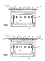
- the hub 16 may also include a vehicle occupant protection apparatus 90, as illustrated in Fig. 5.
- Fig. 5 is a cross-sectional view of the hub portion 22 of the steering wheel 10 of Fig. 1.
- the illustrated vehicle occupant protection apparatus 90 is an air bag module.
- the air bag module 90 includes a housing or reaction can 92.
- the reaction can 92 supports and houses an inflator 94 and an air bag 96, in a deflated condition.
- the hub 16 of the armature 14 forms the reaction can 92 of the air bag module 90.
- a separate reaction can 92 may be fixed to the hub 16 of the armature 14.
- the air bag module 90 operates in a known manner to inflate the air bag 96.
- a front surface 106 of the hub portion 22 of the steering wheel 10 includes a deployment door 108 for the air bag module 90.
- the deployment door 108 encloses the air bag module 90 within the hub portion 22 of the steering wheel 10 and covers an opening 110 through which the air bag 96 inflates.
- the deployment door 108 includes a tear seam 112 that ruptures when subjected to pressure from an expanding air bag 96.
- a heating element 12 may be located under the deployment door 108 in the hub portion 22 of the steering wheel 10.
- the substrate 62 of the heating element 12 is designed to tear at a predetermined pressure.
- the inflating air bag 96 ruptures both the heating element 12 and the deployment door 108 when exiting the hub portion 22 of the steering wheel 10.
- two separate heating elements 12 may be used in the hub portion 22, one located on either side of the tear seam 112 of the deployment door 108.
- the heating element 12 located under the deployment door 108 may be used for two purposes. First, the heating element 12 may be used to heat the hub portion 22 of the steering wheel 10 for comfort of the driver of the vehicle. Second, the heating element 12 may be used to maintain the temperature of the air bag module 90 near a constant temperature. Since the performance of an air bag module 90 may vary as the temperature of the air bag module 90 varies, the heating element 12 may be designed to maintain the temperature of the air bag module 90 at or near a preferred temperature.
- Fig. 6 is a schematic view of a second arrangement of the heating element 12 on a hub portion 22 of the steering wheel 10. Structures in Fig. 6 that are the same as, or similar to, structures of Fig. 5 will be referred to using the same reference numeral.
- the hub portion 22 of the steering wheel 10 of Fig. 6 also includes a deployment door 108 through which the air bag 96 inflates.
- the deployment door 108 includes a tear seam 112 that ruptures when subjected to pressure from an expanding air bag 96.
- the heating element 12 is located above the deployment door 108.
- An outer covering 114 is located above the heating element 12.
- the outer covering 114 may be leather or leather-like material.
- the heating element 12 of Fig. 6 may be used to heat the hub portion 22 of the steering wheel 10 for the comfort of the driver.
- the heating element 12 may also be used to maintain the temperature of the air bag module 90 near a constant temperature.
- the heating element 12 could be attached to the leather or leather-like covering, and thus, the covering and the heating element are wrapped around the steering wheel 10 together. Further, as stated above, the heating element 12 could be applied to any or all of the spokes of the steering wheel 10. Such improvements, changes and modifications within the skill of the art are intended to be covered by the appended claims.
Landscapes
- Engineering & Computer Science (AREA)
- Mechanical Engineering (AREA)
- Chemical & Material Sciences (AREA)
- Combustion & Propulsion (AREA)
- Transportation (AREA)
- Steering Controls (AREA)
Applications Claiming Priority (2)
| Application Number | Priority Date | Filing Date | Title |
|---|---|---|---|
| US09/966,001 US6495799B1 (en) | 2001-09-28 | 2001-09-28 | Steering wheel with self-regulating heating element |
| US966001 | 2001-09-28 |
Publications (2)
| Publication Number | Publication Date |
|---|---|
| EP1298028A2 true EP1298028A2 (de) | 2003-04-02 |
| EP1298028A3 EP1298028A3 (de) | 2003-06-11 |
Family
ID=25510798
Family Applications (1)
| Application Number | Title | Priority Date | Filing Date |
|---|---|---|---|
| EP02021356A Withdrawn EP1298028A3 (de) | 2001-09-28 | 2002-09-23 | Lenkrad mit selbstregelendes elektrisches Heizelement |
Country Status (2)
| Country | Link |
|---|---|
| US (1) | US6495799B1 (de) |
| EP (1) | EP1298028A3 (de) |
Cited By (2)
| Publication number | Priority date | Publication date | Assignee | Title |
|---|---|---|---|---|
| WO2005107322A1 (de) * | 2004-05-04 | 2005-11-10 | Eichenauer Heizelemente Gmbh & Co. Kg | Verfahren zum elektrischen isolieren eines elektrischen funktionselements und derart isolierte funktionselemente aufweisende einrichtung |
| WO2012144743A3 (ko) * | 2011-04-20 | 2013-01-03 | (주)피엔유에코에너지 | 온도 자가조절형 면상발열체를 적용한 스티어링 휠 및 그 제조방법 |
Families Citing this family (23)
| Publication number | Priority date | Publication date | Assignee | Title |
|---|---|---|---|---|
| AU2002257460A1 (en) * | 2002-05-21 | 2003-12-02 | Rhocraft Research And Development Ltd. | Ion exchange membranes and dissolved gas sensors |
| WO2004002806A1 (de) * | 2002-06-28 | 2004-01-08 | W.E.T. Automotive Systems Ag | Lenkrad mit elektrischer heizung |
| US7306283B2 (en) | 2002-11-21 | 2007-12-11 | W.E.T. Automotive Systems Ag | Heater for an automotive vehicle and method of forming same |
| US6727467B1 (en) * | 2003-01-31 | 2004-04-27 | W.E.T. Automotive Systems Ag | Heated handle and method of forming same |
| DE20310682U1 (de) * | 2003-07-11 | 2003-09-18 | TRW Automotive Safety Systems GmbH, 63743 Aschaffenburg | Fahrzeuglenkrad mit Heizelement |
| WO2006131785A2 (en) * | 2004-03-22 | 2006-12-14 | W.E.T. Automotive Systems Ag | Heater for an automotive vehicle and method of forming same |
| US7262388B2 (en) * | 2005-04-28 | 2007-08-28 | Illinois Tool Works Inc | Vehicle light heater |
| US20080127771A1 (en) * | 2006-12-04 | 2008-06-05 | General Electric Company | Steering wheels with integrally molded positive temperature coefficient materials |
| US7849613B2 (en) * | 2007-08-06 | 2010-12-14 | Honda Motor Co., Ltd. | Heated handle apparatuses and methods using power equipment exhaust |
| US20110233183A1 (en) * | 2008-09-03 | 2011-09-29 | North American Rescue, LLC. | Steering wheel heater assembly |
| JP5601301B2 (ja) * | 2011-09-14 | 2014-10-08 | 豊田合成株式会社 | ステアリングホイール及びその製造方法 |
| DE102012020286A1 (de) * | 2012-10-17 | 2014-04-17 | Valeo Schalter Und Sensoren Gmbh | Heizvorrichtung für ein Lenkrad eines Kraftfahrzeugs, Kraftfahrzeug und entsprechendes Verfahren |
| CN106414215B (zh) | 2014-05-22 | 2020-03-17 | Tk控股公司 | 用于屏蔽方向盘中的手传感器系统的系统和方法 |
| US9601923B2 (en) * | 2014-05-30 | 2017-03-21 | Ford Global Technologies, Llc | Current limit management for multi-function systems |
| CN111422238B (zh) | 2014-06-02 | 2022-10-25 | Tk控股公司 | 用于在方向盘的传感器垫上印刷传感器电路的系统和方法 |
| US10336361B2 (en) | 2016-04-04 | 2019-07-02 | Joyson Safety Systems Acquisition Llc | Vehicle accessory control circuit |
| US20180093696A1 (en) * | 2016-09-30 | 2018-04-05 | Ford Global Technologies, Llc | Steering wheel assembly and heated steering wheel system |
| US11046278B2 (en) * | 2017-10-31 | 2021-06-29 | Key Safety Systems, Inc. | Cover assembly for an airbag module |
| JP7223495B2 (ja) * | 2017-11-14 | 2023-02-16 | Joyson Safety Systems Japan合同会社 | ヒータ及びステアリングホイール |
| LU100775B1 (en) * | 2018-04-23 | 2019-10-23 | Iee Sa | Flexible and Strechable Heaters of High Robustness for Automotive Applications |
| US11479286B2 (en) | 2018-03-30 | 2022-10-25 | Iee International Electronics & Engineering S.A. | Flexible and stretchable heaters of high robustness for automotive applications |
| JP7037995B2 (ja) * | 2018-04-13 | 2022-03-17 | Joyson Safety Systems Japan株式会社 | ヒータ及びステアリングホイール |
| FR3132268A1 (fr) * | 2022-01-31 | 2023-08-04 | Autoliv Development Ab | Volant de véhicule avec un dispositif électrique |
Family Cites Families (10)
| Publication number | Priority date | Publication date | Assignee | Title |
|---|---|---|---|---|
| DE438134C (de) * | 1925-11-27 | 1926-12-06 | Josef Horn | Verfahren zum Herstellen von satten, wirkungsvollen Gummidrucken durch mehrmaliges UEbereinanderdrucken der Bogen mittels einer Rotationsgummidruckmaschine |
| JPS5934975A (ja) * | 1982-08-23 | 1984-02-25 | Matsushita Electric Ind Co Ltd | 自動車ハンドル |
| US4931627A (en) | 1988-08-16 | 1990-06-05 | Illinois Tool Works Inc. | Positive temperature coefficient heater with distributed heating capability |
| US4857711A (en) | 1988-08-16 | 1989-08-15 | Illinois Tool Works Inc. | Positive temperature coefficient heater |
| US5111025A (en) | 1990-02-09 | 1992-05-05 | Raychem Corporation | Seat heater |
| US5372379A (en) * | 1994-02-15 | 1994-12-13 | Davidson Textron Inc. | Preheated safety air bag cover |
| US6084217A (en) | 1998-11-09 | 2000-07-04 | Illinois Tool Works Inc. | Heater with PTC element and buss system |
| US6093908A (en) * | 1999-04-30 | 2000-07-25 | Delphi Technologies Inc. | Heated steering wheel |
| US6299466B1 (en) * | 1999-12-29 | 2001-10-09 | Methode Electronics, Inc. | Clockspring using resettable fuse for heated steering wheel |
| US6392195B1 (en) * | 2000-11-27 | 2002-05-21 | Breed Automotive Technology, Inc. | Heated steering wheel |
-
2001
- 2001-09-28 US US09/966,001 patent/US6495799B1/en not_active Expired - Lifetime
-
2002
- 2002-09-23 EP EP02021356A patent/EP1298028A3/de not_active Withdrawn
Cited By (2)
| Publication number | Priority date | Publication date | Assignee | Title |
|---|---|---|---|---|
| WO2005107322A1 (de) * | 2004-05-04 | 2005-11-10 | Eichenauer Heizelemente Gmbh & Co. Kg | Verfahren zum elektrischen isolieren eines elektrischen funktionselements und derart isolierte funktionselemente aufweisende einrichtung |
| WO2012144743A3 (ko) * | 2011-04-20 | 2013-01-03 | (주)피엔유에코에너지 | 온도 자가조절형 면상발열체를 적용한 스티어링 휠 및 그 제조방법 |
Also Published As
| Publication number | Publication date |
|---|---|
| EP1298028A3 (de) | 2003-06-11 |
| US6495799B1 (en) | 2002-12-17 |
Similar Documents
| Publication | Publication Date | Title |
|---|---|---|
| US6495799B1 (en) | Steering wheel with self-regulating heating element | |
| US7145102B2 (en) | Heated handle and method of forming same | |
| JP4173140B2 (ja) | 自動車用ヒータ及びその形成方法 | |
| US10076982B2 (en) | Occupancy sensing with heating devices | |
| EP1337424B1 (de) | Beheizbares lenkrad | |
| EP1612100B1 (de) | Flexibles Sitzheizelement | |
| US6414270B1 (en) | Heater, heater-equipped steering wheel, and method of manufacturing such steering wheel | |
| US7205510B2 (en) | Heater for an automotive vehicle and method of forming same | |
| US20110073582A1 (en) | Steering wheel | |
| US6612609B1 (en) | Inflatable air bag with inner bag and outer bag | |
| CN110116750B (zh) | 方向盘用包覆部件、方向盘及方向盘的制造方法 | |
| US20110233183A1 (en) | Steering wheel heater assembly | |
| US20230219613A1 (en) | Vehicle steering wheel with heating device | |
| US6050597A (en) | Horn switch for air bag module | |
| US5934702A (en) | Horn switch for air bag module | |
| US11453430B2 (en) | Heated vehicle steering wheel having thermal conduction | |
| JP2002096740A (ja) | ステアリング装置 | |
| JP2011207451A (ja) | ステアリングホイール | |
| JP2002104200A (ja) | ステアリング装置 | |
| US6435546B1 (en) | Cover assembly for an air bag | |
| JP2011073545A (ja) | ステアリングホイール | |
| US20030000072A1 (en) | Method of manufacturing an automotive airbag enclosure with an embedded heating element | |
| JP2002096738A (ja) | ヒータ装置及びステアリングホイール | |
| US5957488A (en) | Air bag cover with horn switch | |
| US6279947B1 (en) | Heater for air bag inflator |
Legal Events
| Date | Code | Title | Description |
|---|---|---|---|
| PUAI | Public reference made under article 153(3) epc to a published international application that has entered the european phase |
Free format text: ORIGINAL CODE: 0009012 |
|
| AK | Designated contracting states |
Kind code of ref document: A2 Designated state(s): AT BE BG CH CY CZ DE DK EE ES FI FR GB GR IE IT LI LU MC NL PT SE SK TR Designated state(s): AT BE BG CH CY CZ DE DK EE ES FI FR GB GR IE IT LI LU MC NL PT SE SK TR |
|
| AX | Request for extension of the european patent |
Extension state: AL LT LV MK RO SI |
|
| PUAL | Search report despatched |
Free format text: ORIGINAL CODE: 0009013 |
|
| AK | Designated contracting states |
Designated state(s): AT BE BG CH CY CZ DE DK EE ES FI FR GB GR IE IT LI LU MC NL PT SE SK TR |
|
| AX | Request for extension of the european patent |
Extension state: AL LT LV MK RO SI |
|
| AKX | Designation fees paid | ||
| REG | Reference to a national code |
Ref country code: DE Ref legal event code: 8566 |
|
| STAA | Information on the status of an ep patent application or granted ep patent |
Free format text: STATUS: THE APPLICATION IS DEEMED TO BE WITHDRAWN |
|
| 18D | Application deemed to be withdrawn |
Effective date: 20031212 |